Note: Descriptions are shown in the official language in which they were submitted.
CA 02943206 2016-09-19
WO 2015/142490
PCT/US2015/017917
METHOD AND SYSTEM FOR TRANSFERRING A CALL
BETWEEN DEVICES OF A SINGLE USER
BACKGROUND OF THE INVENTION
[0001] Public safety personnel, such as police officers, firefighters,
paramedics and
the like typically utilize numerous communication devices while working in the
field.
Public safety communication devices include, for example, mobile radios such
as
handheld radios and/or vehicular radios along with remote accessories, such as
remote
microphones, speakers, earpieces, headsets and the like. These primary,
mission
critical devices and the infrastructure to support their operation are
typically realized
in the form of a narrowband system operating via a private network governed by
a
public safety agency.
[0002] Further, public safety personnel often carry additional non-mission
critical
devices, such as cell phones, personal digital assistants, electronic notepads
and the
like which operate over a broadband system. Tlic.'se secondary, non-mission
critical
devices are often used to monitor radio channels that are in addition to radio
channels
monitored using the primary, mission critical devices.
[0003] However, responding to calls that are monitored and received on the
broadband system can be problematic, as non-mission critical broadband devices
often have significant limitations regarding audio and radio frequency
capabilities.
[0004] Accordingly, there is a need for an improved communication method and
system for transferring a call between devices of a single user.
BRIEF DESCRIPTION OF THE SEVERAL VIEWS OF THE DRAWINGS
[0005] The accompanying figures, where like reference numerals refer to
identical or
functionally similar elements throughout the separate views, together with the
detailed
description below, are incorporated in and form part of the specification, and
serve to
further illustrate embodiments of concepts that include the claimed invention,
and
explain various principles and advantages of those embodiments.
CA 02943206 2016-09-19
WO 2015/142490
PCT/US2015/017917
[0006] FIG. 1 is a schematic diagram illustrating a radio communication
system,
according to some embodiments.
[0007] FIG. 2 is a flow diagram illustrating a method of transferring a call
between a
narrowband (NB) device and the broadband (BB) device, according to some
embodiments.
[0008] FIG. 3 is a =block diagram illustrating components of a communication
device,
according to some embodiments.
[0009] FIG. 4 is a flow diagram illustrating a method for transferring a call
between
devices of a single user, according to some embodiments
[0010] Skilled artisans will appreciate that elements in the figures are
illustrated for
simplicity and clarity and have not necessarily been drawn to scale. For
example, the
dimensions of some of the elements in the figures may be exaggerated relative
to
other elements to help to improve understanding of embodiments of the present
invention.
[0011] The apparatus and method components have been represented where
appropriate by conventional symbols in the drawings, showing only those
specific
details that are pertinent to understanding the embodiments of the present
invention so
as not to obscure the disclosure with details that will be readily apparent to
those of
ordinary skill in the art having the benefit of the description herein.
DETAILED DESCRIPTION OF THE INVENTION
[0012] According to some embodiments, the invention is a method for
transferring a
call between devices of a single user. The method comprises pairing, over a
master-
less communication link, a narrowband communication device operating in a
narrowband communication system and a broadband communication device operating
in a broadband communication system. A radio identifier is shared between the
narrowband communication device and the broadband communication device,
enabling call details to be transferred between the narrowband communication
device
and the broadband communication device. The call is then established on both
the
narrowband communication system and the broadband communication system. A
2
CA 02943206 2016-09-19
WO 2015/142490
PCT/US2015/017917
trigger signal is then processed indicating that the call is to be transferred
from one to
the other of the broadband communication device and the narrowband
communication
device. Next, in response to the trigger signal, an operational status of
either the
narrowband communication device or the broadband communication device is
evaluated. The call then can be transferred, using the radio identifier and
the call
details, and based on the operational status, from one to the other of the
broadband
communication device and the narrowband communication device.
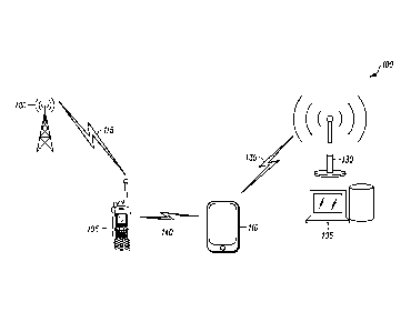
[0013] FIG. 1 is a schematic diagram illustrating a radio communication system
100,
according to some embodiments. The system 100 includes at least one narrowband
device 105 and at least one broadband device 110. The narrowband device 105 is
connected via a wireless link 115 to a narrowband network 120, and the
broadband
device 110 is connected via a wireless link 125 to a broadband network 130.
The
broadband network 130 is then connected to various extended infrastructure
135,
including for example the Internet. Further the narrowband device 105 and the
broadband device 110 are connected to each other via a personal area network
(PAN)
link 140.
[0014] For example, the narrowband network 120 may be a pliblic safety network
used by first responders such as police and fire personnel. The at least one
narrowband device 105 and at least one broadband device 110 can provide a
plurality
of comnrunication devices for a single user, such as a first responder. The
devices
105,110 may be, for exampl.e, handheld devices, devices worn on or about a
user's
body, or devices in a vehicle so as to be under the immediate control of the
user.
[0015] An example of the narrowband device 105 is a dedicated Land Mobile
Radio
(INIR) of a system such as :Project 25 (P25) or European Tefiestrial 'Frunked
Radio
(TETRA) that operates using a Common Air Interface (CAI) call format. An
example
of the broadband device 110 is a conventional cell ph.one, and the wireless
:link 125 to
the broadband network 130 can be established using private or public wireless
networks such as 4G Long Term Evolution (LTE) networks or WiFi networks. The
PAN link :140 connecting together the narrowband device 105 and the broadband
device 110 can be established using various well known master-less wireless
standards and protocols such as Bluetooth, WiFi, or Zi.gBee.
3
CA 02943206 2016-09-19
WO 2015/142490
PCT/US2015/017917
[0016] Advantages of some embodiments include an ability to quickly transfer a
call
from a first device to a second device, where both the first and second
devices are
operated by the same user, but where the second device has improved operating
functionality regarding the transferred call. For example, the broadband
device 110
operates as a partner device for expanding user interface elements to the
narrowband
device 105. Alternatively, the broadband device 110 can operate as a back-up
device
for push-to-talk and emergency communications originating from the narrowband
device 105.
[0017] Thus, in one possibl.e scenario the narrowband device 105 may be, for
example, an LMR device of a police officer who is monitoring a dispatch
channel for
a local police department, and the broadband device 110 may be a cell phone of
the
sante police officer that is monitoring call information and audio streams
availabl.e
over cellular or broadband via Rich Site Summary (RSS) syndication or similar
data.
feeds frora a statewide sheriffs system, which system is separate and
independent of
the system of the local police department. If the police officer is at an
incident scene,
where there may be significant background noise such as vehicle sirens or
alarms, it
can be very beneficial to utilize the superior audio and microphone
capabilities of the
officer's I_MR, device compared to the capabilities of the cell phone. Thus,
according
to some embodiments described herein a call that is first monitored on the
cell phone
can be quickly and effectively transferred to the LMR device.
[0018] FIG, 2 is a flow diagram illustrating a method 200 of transferrin.g a
call
between the narrowband (NB) device 105 and the broadband (BB) device 110
according to some embodinients. At block 205 the devices 105, 11.0 are paired.
For
example, both devices 105, 110 may be carried by a police officer at an
incident scene,
and the devices 105, 1.10 are paired using Bluetooth, At block 210 the
broadband
device 110 is then associated with a particular channel. or talk group,
[0019] At block 215 it is determined whether a triggering event has occurred.
A
triggering event is any event whereby a user of the devices 105, 110 may seek
to
transfer a cali between the devices, 105, 110. For example, a police officer
monitoring a channel on the broadband device 110 may choose to respond on that
same channel, but using the Push To Talk (PIT) functionality, superior audio,
noise
4
CA 02943206 2016-09-19
WO 2015/142490
PCT/US2015/017917
cancelling techniques and superior microphone of the narrowband device 105.
MailUai or autom.ated triggering events may be used, such as for example a
physical
button on either of the devices 105, 110, a sensor or accelerometer switch, or
voice
recognition.
[0020] After it is determined that a triggering event has occurred, at block
220 all
operational status of the narrowband device 105 is evaluated. The operational
status
of the narrowband device 105 can include priority aspects of an operating
mode, such
that priority operation of the narrowband device 105 is not interrupted by
transferring
a call from the broadband device 110 to the narrowband device 105.
[0021] At block 225 it is determined whether a device change is allowed. The
determination is based on factors such as the operational status of the
narrowband
device 105, on the ability- of the narrowband devi.ce 105 to physically switch
to the
channel or talkgroup configuration of the broadband device 110, or the
availability or
authorization of the _narrowband device _105 on the system or talkgro-up
configuration
of the broadband device 1110. For example, if the narrowband device 105 is
operating
in an emergency mode or is performing a priority scan, then it would be
determined
that the current operational status of the narrowband device 105 should take
priority
over a call transfer and the device change would not be allowed. Thus at block
230
the broadband device 110 would alert the user that the device change was
disallowed.
[0022] lf a device change is allowed, then at block 235 the narrowband device
105
transitions to the appropri.ate system, channel or talk group associated with_
the call
transfer. For example, this may include a collaboration event between the
narrowband device 105 and the broadband device 110 to share call details and
call.
encryption keys to allow the user to immediately join a current PTT call that
is in
progress. The user can thus immediately participate in the PTT call using the
narrowband device 105 and does not need to wait for a late entry to the PTT
call.
[0023] At block 240 it is detemined whether the broadband device 110 is able
to
operate in a prior radio configuration or whether the broadband network :130
is
connected with the LMR. system and ta.lkgroup of the narrowband device 105. If
not,
at block 245 the broadband device 110 alerts the user and at block 247 the
broadband
device 110 proceeds in a standby mode. :If so, at block 250 the broadband
device 110
CA 02943206 2016-09-19
WO 2015/142490
PCT/US2015/017917
transitions to an appropriate new channel, system or talkgroup. For example,
the new
channel, system. or talkgroup may have been pre-programmed as a default
configuration of the broadband device 110.
[0024] At block 255 the call on the narrowband device 105 ends or expires. At
block
260 it is then determined whether to all.ow a change on either or both of the
narrowband device 105 and the broadband device 110. If not, at block 265 both
the
narrowband device 105 and the broadband device 110 continue operating in their
current configurations. If so, at block 270 the narrowband device 105 reverts
to an
appropriate channel, system. or talkgroup, and at block 275 the broadband
device 110
reverts to an appropriate channel, system or talkgroup.
[0025] FIG. 3 is a block diagram illustrating components of art embodiment of
a
communication device 300 according to some embodiments. For example, the
narrowband device 105 and the broadband device 110 may each comprise similar
components, architecture and capabilities as the communication device 300.
[0026] The device 300 comprises a memory 305 coupled to a microprocessor 310.
The microprocessor 310 also has ports for coupling to a radio transceiver 315
having
a radio antenna 320, a location sensor 325 having a location antenna 330, and
a
Personal Area Network (PAN)/Wireless Local Area Network (WLAN) transceiver
335 having a PAN/WLAN antenna 340. The location sensor 325 may include, for
example, a Global Positioning System (GPS) location sensor or an indoor
location
sensor. In a narrowband device 105 the radio transceiver 315 communicates with
a
private narrowband network such as the narrowband network 120. In a broadband
device 110 the radio transceiver 315 communicates with broadband
infrastructure
such as the broadband network 130.
[0027] The PAN/WLAN transceiver 335 enables two devices, such as the
narrowband device 105 and the broadband device 110, to communicate with each
other over a PAN or a WLAN using well known standards and protocols such as
Bluetooth, WiFi or Zigbee. The PAN/WLAN transceiver 335 thus enables
establishment of the PAN link 140 between the devices 105, 110, and
transmission of
call transfer details such as encryption keys.
6
CA 02943206 2016-09-19
WO 2015/142490
PCT/US2015/017917
[0028] The memory 305 can store operating code (OC) for the microprocessor 310
and code for performing functions associated with the narrowband device 105 or
the
broadband device 110. For example, the memory 305 can store computer readable
program code components 345 configured to cause execution of a method, such as
the
method 400 described below, for transferring a call between devices of a
single user
as described herein.
[0029] The microprocessor 310 is also connected to user interface elements
such as a
speaker 350, a display unit 355, and input elements 360 such as a microphone
and
keypad. Further, a power supply 365 provides power to the device 300 under
single
user control.
[0030] Wireless portable electronic devices that utilize and benefit from
embodiments
of the present invention can utilize various types of wireless network
architectures
including a mesh enabled architecture (MEA) network, or an Institute of
Electrical
and Electronics Engineers (IEEE) 802.11 network (e.g., 802.11a, 802.11b,
802.11g,
802.11n). It will be appreciated by those of ordinary skill in the art that
such wireless
communication networks can alternatively comprise any packetized communication
network where packets are forwarded across multiple wireless hops. For
example,
such a wireless communication network can be a network utilizing multiple
access
schemes such as OFDMA (orthogonal frequency division multiple access), TDMA
(time division multiple access), FDMA (Frequency Division Multiple Access), or
CSMA (Carrier Sense Multiple Access). Embodiments of the present invention can
then enable a call on such networks to be reliably transferred between devices
such as
the narrowband device 105 and the broadband device 110.
[0031] According to some embodiments, narrowband is defined as a limited-
capacity transmission channel such as that used for transmitting low data rate
audio
signals or data signals. Examples of narrowband within a two-way radio
environment
include Private Land Mobile Radio (PLMR) devices that operate in a 25 kHz or
12.5
kHz bandwidth supporting voice or data operations.
[0032] According to some embodiments, broadband is defined as a high-capacity
transmission technique using a wide range of frequencies, which enables a
large
number of messages to be communicated simultaneously.
7
CA 02943206 2016-09-19
WO 2015/142490
PCT/US2015/017917
[0033] FIG. 4 is a flow diagram illustrating a method 400 for transferring a
call
between devices of a single user, according to some embodiments. At block 405,
a
narrowband communication device operating in a narrowband communication system
is paired over a master-less communication link with a broadband communication
device operating in a broadband communication system. For example, the
narrowband device 105 is paired with the broadband device 110 over a peer-to-
peer
network such as the PAN link 140 in an automated collaboration without user
interaction.
[0034] At block 410, a radio identifier is shared between the narrowband
communication device and the broadband communication device. For example, the
narrowband device 105 and the broadband device 110 identify themselves over
the
PAN link 140.
[0035] At block 415, the call is established on both the narrowband
communication
system and the broadband communication system
[0036] At block 420, a trigger signal is processed indicating that the call is
to be
transferred from one to the other of the broadband communication device and
the
narrowband communication device. For example, the user may manually press a
button on the narrowband device 105 indicating that the call is to be
transferred to the
narrowband device 105 from the broadband device 110.
[0037] At block 425, in response to the trigger signal, an operational status
of either
the narrowband communication device or the broadband communication device is
evaluated. For example, the broadband device 110 evaluates an operational
status of
the narrowband device 105 including priority aspects of an operating mode.
That
ensures that priority narrowband operation of the narrowband device 105 is not
interrupted by transferring the call.
[0038] At block 430, call details are transferred between the narrowband
communication device and the broadband communication device. For example, call
details such as channel information and encryption keys arc transferred
between the
narrowband device 105 and the broadband device 110 over the PAN link 140.
CA 02943206 2016-09-19
WO 2015/142490
PCT/US2015/017917
[0039] At block 435, the call is transferred from one to the other of the
broadband
communication device and the narrowband communication device using the radio
identifier and the call details. For example, the call associated with the
call details
may have been prior established on both the narrowband communication system
and
the broadband communication system so that the call does not require a slow
call
forwarding process but instead can be immediately transferred.
[0040] Advantages of some embodiments thus include an ability to quickly
transfer a
call from a first device to a second device, where both the first and second
devices are
operated by the same user, but where the second device has improved operating
functionality regarding the transferred call. For example, where the second
device is
a narrowband device such as an LMR device, it may have improved audio, noise
cancelling, and microphone capabilities over a first device such as a cell
phone.
Further, according to some embodiments, no disruption occurs of mission
critical
priority aspects of the narrowband device, such as emergency calls and
priority
scanning, because an operational status of the narrowband device is evaluated
before
a call is transferred. Also, according to some embodiments, no server
interaction is
required when transferring a call because the call is already available both
on the
narrowband device (e.g., in a CAI format) and on the broadband device (e.g.,
in a
4G/LTE format).
[0041] In the foregoing specification, specific embodiments have been
described.
However, one of ordinary skill in the art appreciates that various
modifications and
changes can be made without departing from the scope of the invention as set
forth in
the claims below. Accordingly, the specification and figures are to be
regarded in an
illustrative rather than a restrictive sense, and all such modifications are
intended to be
included within the scope of present teachings.
[0042] The benefits, advantages, solutions to problems, and any element(s)
that may
cause any benefit, advantage, or solution to occur or become more pronounced
are not
to be construed as a critical, required, or essential features or elements of
any or all
the claims. The invention is defined solely by the appended claims including
any
amendments made during the pendency of this application and all equivalents of
those
claims as issued.
9
CA 02943206 2016-09-19
WO 2015/142490
PCT/US2015/017917
[0043] Moreover in this document, relational terms such as first and second,
top and
bottom, and the like may be used solely to distinguish one entity or action
from
another entity or action without necessarily requiring or implying any actual
such
relationship or order between such entities or actions. The terms "comprises,"
"comprising," "has", "having," "includes", "including," "contains",
"containing" or
any other variation thereof, are intended to cover a non-exclusive inclusion,
such that
a process, method, article, or apparatus that comprises, has, includes,
contains a list of
elements does not include only those elements but may include other elements
not
expressly listed or inherent to such process, method, article, or apparatus.
An element
proceeded by "comprises a...", "has a...", "includes a...", "contains a..."
does not,
without more constraints, preclude the existence of additional identical
elements in
the process, method, article, or apparatus that comprises, has, includes,
contains the
element. The terms "a" and "an" are defined as one or more unless explicitly
stated
otherwise herein. The terms "substantially", "essentially", "approximately",
"about"
or any other version thereof, are defined as being close to as understood by
one of
ordinary skill in the art, and in one non-limiting embodiment the term is
defined to be
within 10%, in another embodiment within 5%, in another embodiment within 1%
and in another embodiment within 0.5%. The term "coupled" as used herein is
defined as connected, although not necessarily directly and not necessarily
mechanically. A device or structure that is "configured" in a certain way is
configured in at least that way, but may also be configured in ways that are
not listed.
[0044] It will be appreciated that some embodiments may be comprised of one or
more generic or specialized processors (or "processing devices") such as
microprocessors, digital signal processors, customized processors and field
programmable gate arrays (FPGAs) and unique stored program instructions
(including
both software and firmware) that control the one or more processors to
implement, in
conjunction with certain non-processor circuits, some, most, or all of the
functions of
the method and/or apparatus described herein. Alternatively, some or all
functions
could be implemented by a state machine that has no stored program
instructions, or
in one or more application specific integrated circuits (ASICs), in which each
function
or some combinations of certain of the functions are implemented as custom
logic.
Of course, a combination of the two approaches could be used.
[0045] Moreover, an embodiment can be implemented as a computer-readable
storage
medium having computer readable code stored thereon for programming a computer
(e.g., comprising a processor) to perform a method as described and claimed
herein.
Examples of such computer-readable storage mediums include, but are not
limited to,
a hard disk, a CD-ROM, an optical storage device, a magnetic storage device, a
ROM
(Read Only Memory), a PROM (Programmable Read Only Memory), an EPROM
(Erasable Programmable Read Only Memory), an EEPROM (Electrically Erasable
Programmable Read Only Memory) and a Flash memory. Further, it is expected
that
one of ordinary skill, notwithstanding possibly significant cftbrt and many
design
choices motivated by, for example, available time, current technology, and
economic
considerations, when guided by the concepts and principles disclosed herein
will be
readily capable of generating such software instructions and programs and ICs
with
minimal experimentation.
[0046] The Abstract of the Disclosure is provided to allow the reader to
quickly
ascertain the nature of the technical disclosure. ft is submitted with the
understanding
that it will not be used to interpret or limit the scope or meaning of the
claims. In =
addition, in the foregoing Detailed Description, it can be seen that various
features are
grouped together in various embodiments for the purpose of streamlining the
disclosure. This method of disclosure is not to be interpreted as reflecting
an
intention that the claimed embodiments require more features than are
expressly
recited in each claim. Rather, as the following claims reflect, inventive
subject matter
lies in less than all features of a single disclosed embodiment.
11
CA 2943206 2017-12-22