Note: Descriptions are shown in the official language in which they were submitted.
CA 02943433 2016-09-21
WO 2015/150776 PCT/GB2015/050979
DRIVE SYSTEM FOR AIRCRAFT LANDING GEAR
FIELD OF THE INVENTION
The present invention relates to a method of engaging a drive system with a
rotating
wheel of an aircraft landing gear. The present invention also relates to a
drive system
for rotating one or more wheels of an aircraft landing gear for the purposes
of ground
taxiing (forwards or reverse) and/or wheel spin-up prior to landing and/or for
applying
braking torque to the rotating wheel(s).
BACKGROUND OF THE INVENTION
Aircraft are required to ground taxi between locations on airfields. An
example is
taxiing between a runway and the location (e.g. terminal gate) at which the
aircraft's
passengers are to board or disembark. Typically, such taxiing is achieved by
using the
thrust from the aircraft's engines to propel the aircraft forwards so that the
landing
gear wheels are caused to rotate. Since ground taxi speeds are necessarily
relatively
low, the engines must be run at a very low power. This means that there is a
relatively
high fuel consumption as a result of the poor propulsion efficiency at this
low power.
This leads to an increased level of both atmospheric and noise pollution
locally around
airports. Moreover, even when the engines are run at low power it is generally
necessary to apply the wheel brakes to limit ground taxi speeds, leading to a
high
degree of brake wear.
Reversing of a civil aircraft, e.g. away from a terminal gate, using its main
engines is
not permitted. When reversing is necessary, or in other situations where
ground
taxiing via main engine thrust is not practicable, tow trucks are used to
manoeuvre
aircraft around. This process is laborious and costly.
There is therefore a need for a drive system to power the wheels of an
aircraft landing
gear during ground taxi operations. There is also a desire to use such a drive
system
to pre-spin the wheels prior to landing, so that the wheels are already
spinning at, or
near, their initial landing speed on touch down. Such pre-landing spin-up is
perceived
CA 02943433 2016-09-21
WO 2015/150776 PCT/GB2015/050979
2
to reduce tyre wear on landing, and reduce loads transmitted to the landing
gear
during landing.
A known method of engaging a drive system with a wheel of an aircraft landing
gear
is described in W02014/023939. An actuator is arranged to rotate a drive
system
between a position in which a sprocket engages a roller chain, and a position
in which
the sprocket is not able to engage the roller chain.
SUMMARY OF THE INVENTION
A first aspect of the invention provides a method of engaging a drive system
with a
rotating wheel of an aircraft landing gear, the method comprising operating a
motor to
apply torque to a pinion so the pinion rotates; issuing an engagement command
to an
actuator at an engagement time; operating the actuator in response to the
engagement
command to move the pinion from a neutral position to a contact position in
which it
contacts a rotating driven gear at an initial contact time, the rotating
driven gear being
mounted to a rotating wheel of an aircraft landing gear; then after the
initial contact
time operating the actuator to move the pinion further to a meshing position
where the
pinion meshes with the driven gear, wherein a centre-to-centre distance
between the
pinion and the driven gear reduces as the pinion moves to the contact position
and to
the meshing position, and the method further comprises operating the motor to
reduce
the torque to below a predetermined level at or after the engagement time,
maintain
the torque below the predetermined level until the initial contact time, then
after the
initial contact time increase the torque above the predetermined level.
A second aspect of the invention provides a drive system for rotating a wheel
of an
aircraft landing gear, the drive system comprising a pinion; a driven gear
adapted to
be mounted to a wheel of an aircraft landing gear; a motor arranged to apply
torque to
the pinion so the pinion rotates; an actuator which is responsive to an
engagement
command at an engagement time to move the pinion from a neutral position to a
contact position in which it contacts the driven gear at an initial contact
time; then
after the initial contact time to move the pinion further to a meshing
position where
the pinion meshes with the driven gear, wherein a centre-to-centre distance
between
the pinion and the driven gear reduces as the pinion moves to the contact
position and
CA 02943433 2016-09-21
WO 2015/150776 PCT/GB2015/050979
3
to the meshing position, and the drive system further comprises a controller
which is
configured to operate the motor to reduce the torque to below a predetermined
level at
or after the engagement time, maintain the torque below the predetermined
level until
the initial contact time, then after the initial contact time increase the
torque above the
predetermined level.
The motor reduces the torque during a spin-down phase, then re-applies torque
after
the initial contact time (i.e. at the end of the spin-down phase).
The reduction in torque may be initiated by a trigger signal, which may be the
engagement command or some other trigger signal.
The torque may be increased above the predetermined level before or after the
pinion
has moved to the meshing position.
Preferably the driven gear has Ngear teeth or rollers, the pinion has Npinion
teeth or
rollers which mesh with the teeth or rollers of the driven gear when the
pinion is at the
meshing position. The pinion and driven gear are rotating at angular
velocities (Opinion
and Ohear respectively at the initial contact time, and preferably a sync
ratio
R(Dpinion*Npinion) (Ohear*Ngear)] at the initial contact time is not 1. The
sync ratio may
be greater than 1 (for instance greater than 1.02) but more preferably it is
less than 1
(for instance less than 0.98 or less than 0.96).
Optionally a sensor is arranged to detect an angular velocity ()gear of the
driven gear; a
control loop is provided which is responsive to a velocity demand input to
control the
motor so that it rotates at an angular velocity determined by the velocity
demand
input; and a controller is arranged to determine the velocity demand input in
accordance with a gear ratio (Npinion / Ngear), the angular velocity of the
driven gear
detected by the sensor, and a predetermined sync ratio, wherein the
predetermined
sync ratio is chosen so that the pinion is rotating at an angular velocity
(Opinion at the
initial contact time and r(
LµWpinion*Npinion) (0)gear*Ngear)] is not 1.
Typically the driven gear contacts the pinion in a series of impacts as the
pinion
moves from the contact position to the meshing position, and each impact
induces a
spike in electromotive force or angular velocity at the motor. Optionally the
method
CA 02943433 2016-09-21
WO 2015/150776 PCT/GB2015/050979
4
further comprises detecting one of the spikes and operating the motor to vary
the
torque applied to the pinion in response to the detection of one of the
spikes.
Optionally the method further comprises detecting a polarity of the one of the
spikes
and operating the motor to vary the torque applied to the pinion in accordance
with the
detected polarity. The drive system may comprise a sensor arranged to detect
the
spikes; and a controller which is configured to operate the motor to vary the
torque
applied to the pinion in response to the detection of one of the spikes by the
sensor.
In some embodiments the pinion or driven gear may comprise a roller gear
comprising
a series of rollers which mesh with teeth of the driven gear or pinion
respectively. An
advantage of a roller gear is that it is more tolerant of wheel deformation
and
misalignment between pinion and driven gear than meshing toothed gear
arrangements. Each of the series of rollers may be rotatable about a pin, the
pins
optionally being supported by an annular support member, or between two
annular
support members. In other embodiments the series of rollers may be provided by
a
roller chain (also known as an attachment chain, or attachment roller chain)
extending
around an outer circumference of a support member and being fixed thereto.
This
arrangement may be less expensive to implement than the roller gear
arrangement
discussed above.
BRIEF DESCRIPTION OF THE DRAWINGS
Embodiments of the invention will now be described with reference to the
accompanying drawings, in which:
Figure 1 shows an isometric view of a drive system according to a first
embodiment;
Figure 2 shows a further isometric view of the drive system of Figure 1;
Figure 3 shows an isometric view of selected components of a drive system
according
to a second embodiment;
Figure 4 shows an isometric view of a drive system according to a third
embodiment;
Figure 5 shows the drive system of Figure 4 with the pinion in a meshing
position;
CA 02943433 2016-09-21
WO 2015/150776 PCT/GB2015/050979
Figure 6a shows part of a pinion and driven gear in a neutral unengaged
position with
an angular offset of Oc;
Figure 6b shows part of a pinion and driven gear in a neutral unengaged
position with
an angular offset of 0.08c;
5 Figure 7a is a block diagram of the various elements of the drive system;
Figure 7b shows a PI controller;
Figure 8 is a graph showing centre-to-centre distance after 2.5s for a variety
of sync
ratios and angular offsets;
Figure 9 is a pair of graphs comparing centre-to-centre distance and pinion
angular
velocity for low and high engagement forces; and
Figure 10 shows a control method.
DETAILED DESCRIPTION OF EMBODIMENT(S)
The illustrated embodiments are shown applied to an aircraft landing gear
which has
two wheels, but the principles of the embodiments may be applied to landing
gear
with any number of wheels including only a single wheel. The embodiments are
applied to a main landing gear (i.e. a landing gear attached to wing structure
or
fuselage structure in the region of the wings), since the weight supported by
the main
landing gear is considered to provide the best traction between the wheels and
the
ground to enable reliable aircraft ground taxiing. However, the drive system
of the
present invention may alternatively be applied to a nose landing gear (i.e. a
steerable
landing gear towards the nose of the aircraft). The main landing gear shown is
applicable to a single aisle passenger airliner (approximately 150-200 pax),
although it
will be appreciated that this invention has wide applicability to a variety of
aircraft
types and weights, including civil aircraft, military aircraft, helicopters,
passenger
aircraft (<50 pax, 100-150 pax, 150-250 pax, 250-450 pax, >450 pax),
freighters, tilt-
rotor aircraft, etc.
CA 02943433 2016-09-21
WO 2015/150776 PCT/GB2015/050979
6
The landing gear 10 includes a telescopic shock absorbing main leg 12,
including an
upper telescopic part 12a (main fitting) and a lower telescopic part 12b (the
slider).
The upper telescopic part 12a is attached to the aircraft fuselage or wing
(not shown)
by its upper end (not shown). The lower telescopic part 12b supports an axle
14
carrying a pair of wheels 16, one on either side of the main leg (only one
wheel 16 is
shown in Figures 1 and 2, for clarity). The wheels 16 are arranged to rotate
about the
axle 14 to enable ground movement of the aircraft, such as taxiing or landing.
Each wheel 16 comprises a tyre 17 supported by a hub 18 having a rim 18a at
its outer
edge which holds the tyre 17. A driven gear 20 is attached to the hub 18
(preferably at
the rim 18a) so as to be rotatable with the wheel 16. The driven gear 20 may
be
attached to the wheel 16 by a plurality of discrete couplings, which may
provide a
rigid or flexible attachment. Alternatively, the attachment may be via a
flange
forming a continuous extension rim projecting axially from either the wheel 16
or the
driven gear 20.
The drive system 50 includes a motor 52 which transmits torque to a drive
shaft 54 via
a gearbox 70. The drive system 50 is supported by a bracket 56 which is
rigidly
connected to the axle 14 of the landing gear. The bracket 56 includes two lugs
comprising half moon clamps to permit ready attachment and detachment of the
bracket 56 to the axle 14. The motor 52 is fixedly connected, e.g. by bolting,
to the
bracket 56. The gearbox 70 is pivotally connected to the bracket 56.
A drive pinion 60 is mounted on the drive shaft 54 so as to be rotatable by
the drive
shaft about a drive axis. The drive pinion 60, drive shaft 54 and gearbox 70
are
pivotable by a linear actuator (positioner) 58, such as a direct drive roller
screw
electro mechanical linear actuator, which extends between the bracket 56 (at
an end
nearest the axle 15) and the gearbox 70, or more particularly the housing 84
of the
gearbox. Thus, linear movement of the actuator 58 is translated into
rotational
movement of the gearbox 70 and the sprockets 60 about the pivot. The drive
system
50 can therefore be between a neutral configuration (not shown) in which the
drive
pinion 60 does not mesh with the driven gear 20, and a driven configuration
(shown in
Figures 1 and 2) in which the drive pinion 60 is in meshed engagement with the
driven
gear 20. In the neutral configuration the wheel 16 is able to rotate freely,
e.g. during
CA 02943433 2016-09-21
WO 2015/150776 PCT/GB2015/050979
7
take-off and landing, while in the driven configuration the wheel 16 can be
driven by
the drive system 50, e.g. during ground taxiing.
In the embodiment of Figures 1 and 2 the driven gear 20 comprises a roller
gear 24
and the drive pinion 60 comprises a sprocket.
The roller gear is formed by a rigid annular ring 35 and a series of pins
projecting
from both sides of the annular ring 35. A first series of rollers 36a
rotatably supported
by the pins is provided on one side of the annular ring 35, and a second
series of
rollers 36b rotatably supported by the pins as provided on the other side of
the annular
ring. Each series of rollers 36a, 36b extends around the annular ring to form
a
continuous track. First and second lateral annular rings 39a, 39b sandwich the
first
and second series of rollers 36a, 36b. The pins supporting the first series of
rollers
36a extend between the annular ring 35 and the first lateral annular ring 39a,
and the
pins supporting the second series of rollers 36b extend between the annular
ring 35
and the second lateral annular ring 39b. The annular ring 35 therefore forms a
central
spine for supporting the pins which are cantilevered off the central spine.
The annular
ring 35 comprises a plurality of axially extending connection extension tabs
(not
shown) providing mounting means for mounting the roller gear to the hub 18.
Alternatively, the tabs may be substituted for the annular ring 35.
The drive pinion 60 comprises a sprocket having two coaxial rings of radially
extending sprocket teeth which can interlock with the rollers 36 of the roller
gear.
That is, each ring of sprocket teeth is arranged to mesh with one of the rings
of rollers
of the driven gear 20.
Figure 3 shows an alternative, and preferred, embodiment in which the driven
gear
comprises a sprocket instead of a roller gear, and the drive pinion comprises
a roller
gear instead of a sprocket. Thus, the drive pinion comprises a roller gear 64
having
two coaxial rings of rollers and the driven gear 20 is replaced by sprocket 66
having
two coaxial rings of sprocket teeth. In all other respects the drive system is
identical
to that described above with reference to Figures 1 and 2, and the features of
the drive
system described below apply equally to both embodiments. The roller gear 64
may
CA 02943433 2016-09-21
WO 2015/150776 PCT/GB2015/050979
8
be constructed similarly to the roller gear 34, although of course it has a
much smaller
diameter and therefore fewer rollers.
An advantage of the sprocket-roller gear arrangement is that it is more
tolerant of
wheel and axle deformation than meshing toothed gear arrangements. Landing
gear
wheels and axles are subject to high loads and consequential deformation
during
ground taxiing, and a driven gear fixed to the wheel will inevitably deform in
response
to such deformation. Meshing toothed gears are intolerant of such deformation
and a
typical toothed rim gear may need to be isolated from the wheel via bearings,
a
flexible interface, or similar. In contrast, the sprocket and roller
arrangement of the
present invention may be able to tolerate the deformation without such
modification.
Such an arrangement also has the advantage of being lightweight and having
high
structural strength. The main failure mode of the rollers is via shear failure
of the
pins; by mounting each roller directly on its respective pin, with no
intermediate
sleeve, bush or other part, the diameter of the pin can be maximised to
maximise shear
strength.
In a further variation (not shown) the drive pinion may alternatively comprise
a single
ring of rollers for engaging with a driven gear formed as a sprocket (not
shown)
having a single row of sprocket teeth. The roller gear may take many forms,
including
a typical roller gear as in Figure 3, or a roller chain gear.
Figure 4 shows a landing gear 100 incorporating a sprocket-roller gear drive
system of
the kind shown in Figure 3. A driven rim-gear 101 is mounted to a wheel 102. A
roller-gear pinion 103 is driven by a motor 104 via an epicyclic gear box 105.
An
actuator (not shown) can move the pinion 103, gear box 105 and motor 104 from
a
neutral position shown in Figure 4 to a meshing position shown in Figure 5.
Lock
links 106 lock the pinion in the meshing position of Figure 5.
A method of engaging the drive system of Figure 4 with a rotating wheel will
now be
described with reference to Figures 6-10. The method described below can
equally be
applied to the drive systems of Figures 1-3.
CA 02943433 2016-09-21
WO 2015/150776 PCT/GB2015/050979
9
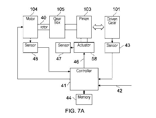
Figure 7a is a schematic diagram showing the main elements of the drive
system. The
motor 104 has a rotor 40 which drives the pinion 103 via the gear box 105. The
drive
system comprises a controller 41 which is configured to operate according to
the
process of Figure 10.
On receipt of an engagement request 42 (from the pilot of the aircraft for
example) in
step 400 a measurement is taken by a sensor 43 to determine the current
angular
velocity of the driven gear. The motor is then commanded to apply torque at
step 401
to the pinion so that the pinion starts rotating. The applied torque is
controlled by a
proportional-integral (PI) torque control loop 410 shown in Figure 7b so that
the
pinion accelerates in a spin-up phase up to a desired angular velocity. The
desired
angular velocity is controlled by a velocity demand input 45 to the control
loop from
the controller 41. The velocity demand input 45 is determined by the
controller 41 in
accordance with a current angular velocity of the driven gear measured by the
sensor
43, the known gear ratio between the pinion and the driven gear, and a
predetermined
sync ratio stored in a memory 44.
When the pinion has reached the desired angular velocity in step 402 at the
end of the
spin-up phase then the controller 41 suspends the roller gear torque control
loop 410
and generates an engagement command 46 in step 403 which causes the linear
actuator 58 to initiate an engagement phase during which the pinion moves into
engagement with the driven gear. In a first part of the engagement phase the
pinion
moves from the neutral position of Figure 6a to a contact position in which it
contacts
the rotating driven gear at an initial contact time. This initial contact time
is the time
at which the pinion makes its first contact with the driven gear during the
engagement
phase. After this initial contact time, in a second part of the engagement
phase the
actuator 58 attempts to push the pinion further beyond the contact position to
a
meshing position where the pinion fully meshes with the driven gear, with the
rollers
positioned towards the base of the groove between the teeth of the driven
gear. The
centre-to-centre distance between the rotation axis of the pinion and the
rotation axis
of the driven gear reduces as the pinion moves to the contact position and to
the
meshing position. In other words, the motion of the pinion is not parallel
with its axis
of rotation but rather it is radial (or at least predominantly radial) with
respect to its
axis of rotation.
CA 02943433 2016-09-21
WO 2015/150776 PCT/GB2015/050979
The driven gear has Ngear teeth and the pinion has Npinion rollers which mesh
with the
teeth of the driven gear when the pinion is at the meshing position. Ngear is
greater
than Npinion. Typically Ngear is 40 and Npinion is 11, giving a gear ratio of
40/11=3.64.
This gear ratio is stored in the memory 44 along with the predetermined sync
ratio.
5 The pinion and driven gear are rotating at angular velocities (Opinion
and Ohear
respectively as the pinion contacts the driven gear at the initial contact
time. A sync
ratio parameter R = [(Wpinion*Npi,,i
. ( ,_rn
gear*Ngear)] determines the relative speed of
the rollers of the pinion and the teeth of the driven gear at this initial
contact time. If
the sync ratio R is 1, then a point on the pitch circle of the pinion (i.e.
the centre of
10 one of the rollers) is travelling at the same speed as a point on the
pitch circle of the
driven gear (about half way up one of the teeth).
The sync ratio at the initial contact time must be chosen to achieve meshing
of the
gears without significant actuation force from the actuator 58. Figure 8 is a
graph
illustrating the effect of varying the sync ratio. The X-axis in Figure 8
represents the
predetermined sync ratio stored in the memory, and the Y-axis represents a
centre-to-
centre distance between the pinion and driven gear. Figure 8 is derived from a
computer model which models the behaviour of the pinion as it is engaged. The
computer model assumes that the driven gear is rotating at (Dgear, the pinion
is being
driven radially towards the driven gear by the actuator with a given force,
and the
pinion is being spun at a particular angular velocity based on a given
predetermined
sync ratio. Each data point in Figure 8 represents the centre-to-centre
distance 2.5
seconds after the engagement command, for a given sync ratio and a given
angular
relative position of the gears when the computer model starts to run. So for
example
data point 120 is associated with a run of the computer model which starts at
the "Oc"
angular relative position shown in Figure 6a (in which a roller of the pinion
is aligned
with a groove between the teeth of the driven gear) with a sync ratio of about
0. In
this case the pinion and driven gear have not meshed fully, resulting in a
centre-to-
centre distance of about 347mm after 2.5s. On the other hand data point 121 is
associated with a run of the computer model which starts at the "0.08c"
angular
relative position shown in Figure 6b (in which a roller of the pinion is
aligned with a
tooth of the driven gear) with a sync ratio of about 0.92. Again the pinion
and driven
gear have not meshed fully, resulting in a centre-to-centre distance of about
347mm
CA 02943433 2016-09-21
WO 2015/150776 PCT/GB2015/050979
11
after 2.5s. Data point 122 on the other hand shows a successful meshing
operation
based on a sync ratio of 0.95. In this case the centre-to-centre ratio is
about 336mm,
indicating that the pinion and driven gear have meshed fully.
Data point 123 on the other hand shows an unsuccessful meshing operation based
on a
low sync ratio of 0.8. In this case the centre-to-centre ratio is about 357mm
which is
close to the centre-to-centre distance at the neutral position of Figures 6a
and 6b. This
indicates that for this low sync ratio the pinion has been repeatedly forced
back by a
series of tooth to roller impacts, and completely failed to mesh. Similarly
data point
124 shows an unsuccessful meshing operation based on a high sync ratio of 1.2.
In
this case the centre-to-centre ratio is also about 357mm which is close to the
centre-to-
centre distance at the neutral position of Figures 6a and 6b. This indicates
that for this
high sync ratio the pinion has been repeatedly forced back by a series of
tooth to roller
impacts, and completely failed to mesh.
It should be noted that no position sensor is available so the angular
relative position
between the pinion and the driven gear is not known. In other words, as the
pinion
comes into contact with the driven gear it may be perfectly aligned (as shown
in
Figure 6a) with the rollers between the teeth, or there may be a clash (as
shown in
Figure 6b) with the rollers aligned with the teeth.
Figure 8 shows that there is a "window" of optimal sync ratio between about
0.9 and 1
in which the pinion and gear are able to mesh successfully. Increasing the
force
applied by the actuator 58 has the effect of widening this window, but at the
expense
of increasing tooth loading, noise and vibration. Also, increasing the inertia
in the
drive train from the pinion to the motor would have the effect of narrowing
the
window.
Surprisingly, a sync ratio of 1 has been found to be undesirable, as evidenced
by the
data point 125. This data point 125 shows a run of the computer model in which
the
sync ratio is approximately 1, and the pinion repeatedly "skips" off the teeth
of the
driven gear.
Another surprising feature of Figure 8 is that it shows that a sync ratio of 1
is at the
upper end of the window rather than its mid-point. In other words, Figure 8
shows
CA 02943433 2016-09-21
WO 2015/150776 PCT/GB2015/050979
12
that an ideal sync ratio is slightly less than 1 - of the order of 0.95. This
asymmetry is
observed to increase as the computer model is changed to use a higher
actuation force
- that is, the window increases further out to the left in Figure 8 than to
the right.
These two surprising features of Figure 8 suggest two related conclusions. The
first
feature suggests that bringing the pinion and driven gear together at a sync
ratio of 1
(at which the rollers and teeth are moving at essentially the same speed) is
undesirable. The second feature suggests that that moving the rollers slower
than the
teeth (i.e. with a sync ratio less than 1) is desirable. Consequently the
velocity
demand input 45 is chosen so that the sync ratio Koopinion*Npinion) /
(ohear*Ngear)] at the
initial contact time is less than 1.
As noted above, when the pinion has reached the desired angular velocity
(determined
by the velocity demand input 45) at the end of the spin-up phase in step 402
then the
actuator moves the pinion into engagement with the driven gear in response to
an
engagement command 46 in step 403. This engagement command is also used as a
trigger to suspend torque control from the control loop 410 and reduce the
output
torque of the motor 104, ideally to zero or at least below some predetermined
low
level stored in the memory 44 (which typically represents a reduction of 90%
or more
compared with the torque being applied immediately before receipt of the
engagement
command). This initiates a spin-down phase in which the rotor 40 is no longer
applying significant torque to the pinion so the pinion will gradually start
to slow
down. The motor maintains the torque at zero (or below the predetermined low
level)
at least until the pinion has reached the contact position at the initial
contact time, and
possibly for longer. It is expected that the period of time between receipt of
the
engagement command and the initial contact time will be relatively short (of
the order
of 0.5s) so the reduction in angular velocity of the pinion will be relatively
small. As
a result the angular velocity of the pinion at the initial contact time will
be (00pinion-A),
where A is the small reduction in angular velocity during the spin-down phase.
Equivalently the sync ratio of the pinion at the initial contact time will be
(R-6), where
R is the predetermined sync ratio stored in the memory 44, and 6 is the small
reduction in sync ratio during the spin-down phase.
CA 02943433 2016-09-21
WO 2015/150776 PCT/GB2015/050979
13
Reducing (or completely eliminating) the torque being applied by the motor at
the
initial contact time inputs less energy into the system and improves the
probability of
a successful meshing operation.
In the example given above, the engagement command 46 to the actuator acts as
a
trigger to initiate the spin down phase. However other trigger signals may be
used as
a trigger to cause the motor to reduce its torque output and initiate the spin
down
phase. For example a sensor 47 may detect when the centre-to-centre distance
falls
below a predetermined threshold (after the engagement command but before the
initial
contact time) and the controller uses that as a trigger. Alternatively the
engagement
command 46 may be used as a trigger, but the spin down phase delayed by some
pre-
determined time rather than being immediately initiated. Alternatively the
detection
of the desired angular velocity at the end of the spin-up phase may be used as
a torque
reduction trigger rather than the engagement command itself
After the initial contact time the spin-down phase comes to an end, and the
motor can
now increase the torque above the low level via a gradual ramp in step 406
after the
meshing position has been achieved at step 408, or in a torque control step
405 before
the meshing position has been achieved. This torque control step 405 is
described
below.
During the meshing phase (i.e. after the initial contact time but before the
pinion has
reached the meshing position) the driven gear contacts the pinion in a series
of
impacts, each impact induces a back electromotive force (EMF) spike in the
motor
and also a related spike in angular velocity of the rotor 40. The polarity of
the
EMF/velocity spike will depend on which side of a tooth is impacting the
roller (i.e.
the impact may have the effect of speeding up the roller, or slowing it down).
A
sensor 48 is arranged to detect the amplitude and polarity of these spikes,
and the
controller 41 is configured to vary the torque applied to the pinion in
response to this
detection. The sensor 48 may sense the EMF of the motor 104, or the angular
velocity
of the rotor 40 (using a resolver for example). If the sensor 48 detects a
positive spike
indicating that the pinion speed has been increased by a tooth impact, then
the motor
is commanded to reduce its output torque by a fixed magnitude. Alternatively
if the
sensor detects a negative spike indicating that the pinion has been slowed
down by a
CA 02943433 2016-09-21
WO 2015/150776 PCT/GB2015/050979
14
tooth impact, then the motor is commanded to increase its output torque by a
fixed
magnitude. The torque control loop based on the detection of these spikes is
illustrated by steps 404 and 405 in Figure 10.
If it is detected at step 407 that the pinion angular velocity has moved
outside a
defined velocity window relative to the driven gear, then the control returns
to the
torque control loop 410 so the pinion is driven by the motor back to a desired
velocity.
Figure 9 shows a pair of graphs. The top graph has a first trace showing the
centre-to-
centre distance over time for a first computer model with an actuation force
of 1500N,
and a second trace showing the centre-to-centre distance over time for a
second
computer model with an actuation force of 3000N. The first trace shows an
initial
contact at initial contact time 200, followed by a series of spikes 201 caused
by
impacts in which the pinion "skips" off the driven gear (note that an
equivalent series
of EMF/velocity spikes will be detected at the motor by the sensor 48). The
pinion in
this case never reaches the meshing position (centre-to-centre distance
336mm). The
second trace shows a first contact at initial contact time 210, followed by a
series of
spikes 211 caused by impacts during the meshing phase, followed by a
continuous
drop 212 in centre-to-centre distance as the pinion moves to the meshing
position 213.
For both traces the controller issues the engagement command to the actuator
at an
engagement time 215.
The bottom graph in Figure 9 shows traces from the same two computer models,
this
time shown the angular velocity of the pinion. The initial angular velocity is
low (the
predetermined sync ratio stored in the memory 44 being 0.85). For the first
computer
model with the lower actuation force, the trace shows a series of small steps
300 in
which the angular velocity increases. The high inertia of the drive path
between the
motor and the pinion means that the impacts have limited effect on the angular
velocity of the pinion. For the second computer model with the higher
actuation
force, the trace shows a series of larger steps 310 as the pinion moves to the
meshing
position. This demonstrates that with a greater engagement load each impact
imparts
more force to the pinion so that it can drop into engagement at a sync ratio
of about
0.96 (both computer models begin at a predetermined sync ratio of 0.85).
Clearly
each impact is sub-optimal, and increasing the force increases shock, loads
and noise.
CA 02943433 2016-09-21
WO 2015/150776 PCT/GB2015/050979
The embodiments described above are suitable only for ground taxiing
operations but
could be modified (e.g. by adjustment of the gearbox ratio) to be suitable for
only pre-
landing spin-up operations. In the taxiing configuration the linear actuator
58 (which
may be back drivable) may be torque controlled (or current controlled) to
apply a
5 substantially constant load between the pinion and the driven gear,
thereby allowing
for some deformation of the various component parts of the drive system while
at the
same time preventing unwanted separation. An electro mechanical brake (not
shown),
or other similar blocking device, may be integrated within the actuator 58 to
lock the
actuator in the disengaged (second) configuration.
10 In each of the arrangements described above the principle of achieving
drive via
meshing between a sprocket and roller gear/roller chain can be applied when
the
driven gear comprises the sprocket and the drive pinion comprises the roller
gear/roller chain, and vice versa.
Although the figures only show features of the drive system for driving one of
the
15 wheels, it is envisaged that these features may be mirrored for the
other wheel. That
is, it is envisaged that one drive system may be provided for each wheel. For
a
landing gear with four or more wheels, a drive system may be provided for each
of the
wheels, or for only two of them. In embodiments in which only two of the
wheels are
provided with drive systems, it may be necessary to provide further motors
(not
shown) to achieve pre-landing spin-up of the un-driven wheels, with ground
taxiing
being accomplished by the two drive systems. In other embodiments it may be
possible to have one motor shared between two drive systems. That is, the
motor may
be arranged to rotate the input shaft of the gearbox of each drive system.
Although the figures only show the drive system 50 supported by a bracket 56
which
is rigidly connected to the axle 14 of the landing gear, the drive system 50
may
alternatively be mounted on the upper telescopic part 12a (main fitting) or
lower
telescopic part 12b (slider).
Although the invention has been described above with reference to one or more
preferred embodiments, it will be appreciated that various changes or
modifications
CA 02943433 2016-09-21
WO 2015/150776 PCT/GB2015/050979
16
may be made without departing from the scope of the invention as defined in
the
appended claims.