Language selection

Search

Patent 2943509 Summary

Third-party information liability

Some of the information on this Web page has been provided by external sources. The Government of Canada is not responsible for the accuracy, reliability or currency of the information supplied by external sources. Users wishing to rely upon this information should consult directly with the source of the information. Content provided by external sources is not subject to official languages, privacy and accessibility requirements.

Claims and Abstract availability

Any discrepancies in the text and image of the Claims and Abstract are due to differing posting times. Text of the Claims and Abstract are posted:

  • At the time the application is open to public inspection;
  • At the time of issue of the patent (grant).
(12) Patent: (11) CA 2943509
(54) English Title: CHILDREN'S VEHICLE
(54) French Title: VEHICULE D'ENFANT
Status: Granted and Issued
Bibliographic Data
(51) International Patent Classification (IPC):
  • B60N 2/08 (2006.01)
  • B60N 2/06 (2006.01)
(72) Inventors :
  • RAINER, LUTHER (Germany)
(73) Owners :
  • FRANZ SCHNEIDER GMBH & CO. KG
(71) Applicants :
  • FRANZ SCHNEIDER GMBH & CO. KG (Germany)
(74) Agent: MCKAY-CAREY & COMPANY
(74) Associate agent:
(45) Issued: 2022-09-06
(22) Filed Date: 2016-09-29
(41) Open to Public Inspection: 2017-07-21
Examination requested: 2021-02-11
Availability of licence: N/A
Dedicated to the Public: N/A
(25) Language of filing: English

Patent Cooperation Treaty (PCT): No

(30) Application Priority Data:
Application No. Country/Territory Date
10 2016 000 524.6 (Germany) 2016-01-21

Abstracts

English Abstract

The children's vehicle with a seat is characterised by an adjustable locking device, with which a desired position of the seat in the longitudinal direction of the children's vehicle may be set, and a security locking device, which only releases the adjustable locking device for adjustment of the current position when the seat is unloaded.


French Abstract

Le véhicule pour enfant avec un siège est caractérisé par un dispositif de verrouillage ajustable, par lequel une position souhaitée du siège dans le sens longitudinal du véhicule peut être réglée, et un dispositif de verrouillage de sécurité, qui libère seulement le dispositif de verrouillage ajustable pour lajustement de la position actuelle lorsque le siège est déchargé.

Claims

Note: Claims are shown in the official language in which they were submitted.

Claims
1. A children's vehicle comprising the children's vehicle with a seat, the
seat having
an adjustable locking device with which a selected position of the seat in the
longitudinal direction (A) of the children's vehicle may be set, and a
security
locking device which only releases the adjustable locking device for
adjustment of
the current position when the seat is unloaded.
2. The children's vehicle as claimed in claim 1, wherein, arranged on a
base body of
the children's vehicle is a seat block, which has recesses of the adjustable
locking
device and the security locking device, the recesses being spaced apart in a
longitudinal direction.
3. The children's vehicle as claimed in claim 1 or 2, wherein, fastened
beneath the
seat there is a frame portion with a base wall and two parallel side walls,
projecting
inwardly from which are guide elements which engage in guide grooves formed in
outer walls of the seat block.
4. The children's vehicle as claimed in claim 3, wherein the adjustable
locking device
has at least one spring arm which is fastened to the base wall and has at an
end
region a downwardly projecting locking element which fits into the recesses of
the
adjustable locking device and, in the relaxed state of the spring arm, engages
into
one of the recesses.
5. The children's vehicle as claimed in claim 4, wherein two laterally
spaced spring
arms with a respective locking element and two correspondingly laterally
spaced
rows of recesses are provided.
6. The children's vehicle as claimed in claims 4 or 5, wherein the security
locking
device has a spring device and at least one locking element on the base wall
and
associated depressions, spaced apart in the longitudinal direction, in the
seat
block, wherein the spring device projects downwardly from the base wall in the
relaxed state such that the at least one locking element is out of the
depressions.
7. The children's vehicle as claimed in claim 6, wherein the spring device
is a curved
leaf spring which is attached to an edge of an opening in the base wall and,
when

the seat is loaded, is forced into the opening, whereby the at least one
locking
element moves into one of the depressions.
8. The children's vehicle as claimed in claim 6 or 7, wherein the locking
elements are
formed on both sides of the spring device and two rows of the depressions
aligned
with one another are formed in the seat block.
9. The children's vehicle as claimed in any one of claims 4 to 8, wherein
the at least
one spring arm, preferably two spring arms, are connected to a handle
projecting
forwardly beyond the seat, which may be raised so that the locking elements of
the
adjustable locking device move out of the depressions.
10. The children's vehicle as claimed in claim 3, wherein the guide grooves
in the
outer walls of the seat block have a constriction, which acts as a stop for
rear
guide elements of the guide elements on the frame portion to limit forward
movement of the seat.
6

Description

Note: Descriptions are shown in the official language in which they were submitted.


CA 02943509 2016-09-29
Children's Vehicle
The invention relates to a children's vehicle with a seat, on which a child
sits in order, for
instance, to drive the vehicle with a foot pedal. The children's vehicle can,
however, also
have a motor or be a so-called ride-on vehicle, in which a child pushes off
from the ground
with his feet.
The invention will be described below in connection with a pedal vehicle.
Children's vehicles of the type in question commonly have a fixed, immovable
seat.
Since this type of a children's vehicle is used by children of different ages
and different
sizes, there is a problem that not every child can reach the pedals so that he
can operate
them whilst seated in a relaxed and calm manner on the vehicle seat. If a
child is too
small to reach the pedals with a relaxed posture, the child can slide forwards
on his seat,
whereby there is the danger that the child falls off the vehicle, e.g. when
going round a
corner. Large children with long legs can have the problem of having to pull
their legs in
too much when riding.
In some embodiments of the present invention the seat is arranged adjustably
without the
adjustability being associated with danger or the risk of injury for a child
who wants to
operate the adjustment mechanism whilst moving.
The invention provides that the children's vehicle includes an adjustable
locking device,
with which one of a number of possible positions of the seat in the
longitudinal direction of
the children's vehicle may be set, and a security locking device, which only
permits the
adjustment of the position of the seat when the seat is not loaded by a
weight. This is to
be understood as meaning that the security locking device prevents adjustment
of the
position of the seat when a child is sitting on the vehicle seat. In order to
be able to move
the seat, the child must get off the vehicle, whereby the adjustment mechanism
is
released.
A child is thus reliably prevented from adjusting the seat whilst moving and
also in the rest
state of the children's vehicle while he is sitting on the seat so that a
child is precluded
from falling off the vehicle or otherwise injuring himself as a result of
movement of the
seat.
1 5126189v1

CA 02943509 2016-09-29
In an embodiment of the invention, a seat block can be arranged on the chassis
of the
children's vehicle, which is either constructed integrally with the chassis or
base body of
the children's vehicle, when it is made preferably by a blow-moulding method,
or which is,
for instance, screwed to the base body. This base body should have depressions
of the
adjustable locking device and the security locking device spaced apart in the
longitudinal
direction. It is further proposed that secured beneath the seat there is a
frame portion,
which has a base wall and two parallel side walls, projecting inwardly from
which are
guide elements, which engage into guide grooves in the outer walls of the seat
block. The
guide elements can have a different height. It is preferred that each side
wall has a front
and a rear guide element, wherein the rear guide elements have a greater
height than the
front guide elements. The seat is secured with its frame portion on the seat
block so that
it is inserted from the rear edge of the seat block with the guide elements in
the guide
grooves and slid forwardly until the adjustment mechanism described below
locks into a
selected position in the longitudinal direction of the seat block. The guide
grooves in the
outer walls of the seat block have a constriction approximately in the middle
of their
length, which serves as an abutment for the larger rear guide elements on the
frame
portion so that the seat cannot be moved further forward on the seat block.
The adjustable locking device has at least one spring arm, preferably two
laterally spaced
spring arms, which have locking elements in the end region projecting
downwardly from
the base wall, i.e. towards the seat block, which fit into the depressions of
the adjustable
locking device in the seat block and, in the relaxed state of the spring arms,
engage into
respective recesses. The two spring arms arranged adjacent one another are
preferably
fastened to, preferably integrally formed on, the edge of an associated
opening, wherein
the longitudinal sides and the free end side of the spring arms can be cut
free from the
base wall, when their material is sufficiently elastic.
The two spring arms are connected to a handle, which projects forwardly beyond
the seat
and is liftable in order to permit the locking elements on the free end region
of the spring
arms to move out of the depressions in the seat block and to adjust the
position of the
seat, when this is permitted by the security locking device described below.
The security locking device has at least one spring and at least one locking
element on
the base wall and associated depressions, spaced apart in the longitudinal
direction, in
the seat block, wherein the at least one spring projects downwardly from the
base wall,
i.e. towards the seat block, in its relaxed state and raises the base wall
with respect to the
seat block, when no one is sitting on the seat, whereby, in this state, the at
least one
2 5126189v1

CA 02943509 2016-09-29
locking element is held above the depressions. When, on the other hand, the
child sits on
the seat, the base wall is forced downwardly against the action of the spring,
whereby the
at least one locking element moves into one of the depressions.
The spring device preferably consists of a curved leaf spring, which can be
attached to the
edge of an opening so that, when the seat is loaded, the leaf spring is
pressed into the
opening and the at least one locking element moves into the depressions. It is
preferred
that locking elements are formed on both sides of the leaf spring and that two
rows of
depressions aligned with one another are formed in the seat block. It is
stressed in this
connection that the arrangement can also be reversed in that the locking
elements project
from the seat block and corresponding depressions are formed in the base wall.
Further details of the invention will be apparent from the following
description of a
preferred embodiment of the children's vehicle and with the aid of the
drawings, in which:
Figure 1 shows the components of the seat in an exploded view;
Figure 2 shows the assembled seat;
Figure 3 is a perspective view of the seat from below;
Figure 4 is an underneath view of the seat;
Figure 5 is a rear view of the seat;
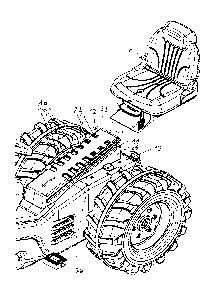
Figure 6 shows the rear portion of a children's pedal vehicle and the
seat before it is
fitted;
Figure 7 shows the seat in the rearward position on the children's
vehicle; and
Figure 8 shows the seat in a moved forward position.
Beneath the seat 1, which is made of plastic material in a blow-moulding
method, a frame
portion 2 is screwed on by means of two screws 3, which are screwed into an
internal
screw thread in bosses 5 on the frame portion 2 through holes 4 in the seat 1.
The frame
portion 2, which is stiffened by transverse and longitudinal walls 6,
includes, as is shown
in particular in Figure 3, on its underside two parallel side walls 7, which
project away from
a base wall 8.
Attached to the inner sides of the side walls 7 are respective front guide
elements 9 and
rear guide elements 10. These guide elements 9, 10 engage, when the assembled
seat is
fitted, in lateral guide grooves 11 in a seat block 12, as shown in Figure 6.
The seat block
12 is a fixed component of the vehicle base body 13.
3 5126189v1

CA 02943509 2016-09-29
As shown, in particular, in Figures 3 and 4, two spring arms 14 are cut free
from the base
wall 8, which have at their free ends a respective locking element 15 of
substantially cubic
shape projecting downwardly, i.e. towards the seat block 12. These locking
elements 15
are provided for engagement in a respective one of four depressions, which are
spaced
from one another in the longitudinal direction (arrow A), in the seat block
11. The two
spring arms 14 are connected in the region of the locking elements 15 by
screws 17 to a
handle 18 which, as shown Figure 2, projects forwardly beneath the seat 1 and
can be
raised so that the locking elements 15 move out of the respective depressions
16.
Projecting from the underside of the base wall 8 in the region of its rear end
section there
is a curved leaf spring 19, which is fastened to or integrally formed on the
edge of an
opening 20. Projecting downwardly from the underside of the base wall 8 on
both sides of
the leaf spring 19 there are also locking elements 21, which fit into
depressions 22 in the
upper wall 23 of the seat block 12. The leaf spring 19 engages the wall 23 of
the seat
block 11 between the depressions 22.
When no one is sitting on the seat 1, the leaf spring 19 raises the entire
seat so far that
the locking elements 21 move out of the associated depressions 22. The
position of the
seat can be adjusted in this state. However, when a child sits on the seat 1,
the leaf
spring 19 is forced back and the locking elements 21 locate in associated
depressions 22
so that the adjustment mechanism is locked.
The guide grooves 11 in the seat block 12 have a discontinuity or constriction
26, which
act as a stop for the guide elements 10, which are higher than the guide
elements 9. The
lower edge 24 of the side wall 7 has an angular shape which is matched to the
shape of
the side walls 25 of the seat block 12 on the base body 13.
Figure 6 shows that the assembled seat 1 is slid onto the seat block 12 from
the rear of
the pedal vehicle. Figure 7 shows the rear position of the seat on the seat
block 12, on
which, after raising the handle 18 (arrow B) the seat can be slid forwardly,
which is
indicated by the arrow C. Figure 8 shows the front end position of the seat 1
from which
the seat can be slid back, when no child is sitting on the seat.
4 5126189v1

Representative Drawing
A single figure which represents the drawing illustrating the invention.
Administrative Status

2024-08-01:As part of the Next Generation Patents (NGP) transition, the Canadian Patents Database (CPD) now contains a more detailed Event History, which replicates the Event Log of our new back-office solution.

Please note that "Inactive:" events refers to events no longer in use in our new back-office solution.

For a clearer understanding of the status of the application/patent presented on this page, the site Disclaimer , as well as the definitions for Patent , Event History , Maintenance Fee  and Payment History  should be consulted.

Event History

Description Date
Maintenance Request Received 2024-08-08
Maintenance Fee Payment Determined Compliant 2024-08-08
Inactive: Grant downloaded 2022-09-21
Grant by Issuance 2022-09-06
Letter Sent 2022-09-06
Inactive: Cover page published 2022-09-05
Pre-grant 2022-06-27
Inactive: Final fee received 2022-06-27
Letter Sent 2022-05-24
Notice of Allowance is Issued 2022-05-24
Inactive: Approved for allowance (AFA) 2022-04-08
Inactive: Q2 passed 2022-04-08
Letter Sent 2021-02-19
Request for Examination Received 2021-02-11
All Requirements for Examination Determined Compliant 2021-02-11
Request for Examination Requirements Determined Compliant 2021-02-11
Common Representative Appointed 2020-11-07
Common Representative Appointed 2019-10-30
Application Published (Open to Public Inspection) 2017-07-21
Inactive: Cover page published 2017-07-20
Inactive: Reply to s.37 Rules - Non-PCT 2016-12-12
Inactive: IPC assigned 2016-11-30
Inactive: First IPC assigned 2016-11-30
Inactive: Filing certificate - No RFE (bilingual) 2016-10-06
Filing Requirements Determined Compliant 2016-10-06
Application Received - Regular National 2016-09-30

Abandonment History

There is no abandonment history.

Maintenance Fee

The last payment was received on 2021-09-24

Note : If the full payment has not been received on or before the date indicated, a further fee may be required which may be one of the following

  • the reinstatement fee;
  • the late payment fee; or
  • additional fee to reverse deemed expiry.

Please refer to the CIPO Patent Fees web page to see all current fee amounts.

Fee History

Fee Type Anniversary Year Due Date Paid Date
Application fee - standard 2016-09-29
MF (application, 2nd anniv.) - standard 02 2018-10-01 2018-09-18
MF (application, 3rd anniv.) - standard 03 2019-09-30 2019-07-30
MF (application, 4th anniv.) - standard 04 2020-09-29 2020-09-25
Request for examination - standard 2021-09-29 2021-02-11
MF (application, 5th anniv.) - standard 05 2021-09-29 2021-09-24
Final fee - standard 2022-09-26 2022-06-27
MF (patent, 6th anniv.) - standard 2022-09-29 2022-09-26
MF (patent, 7th anniv.) - standard 2023-09-29 2023-07-19
MF (patent, 8th anniv.) - standard 2024-10-01 2024-08-08
Owners on Record

Note: Records showing the ownership history in alphabetical order.

Current Owners on Record
FRANZ SCHNEIDER GMBH & CO. KG
Past Owners on Record
LUTHER RAINER
Past Owners that do not appear in the "Owners on Record" listing will appear in other documentation within the application.
Documents

To view selected files, please enter reCAPTCHA code :


To view images, click a link in the Document Description column. To download the documents, select one or more checkboxes in the first column and then click the "Download Selected in PDF format (Zip Archive)" or the "Download Selected as Single PDF" button.

List of published and non-published patent-specific documents on the CPD .

If you have any difficulty accessing content, you can call the Client Service Centre at 1-866-997-1936 or send them an e-mail at CIPO Client Service Centre.


Document
Description 
Date
(yyyy-mm-dd) 
Number of pages   Size of Image (KB) 
Cover Page 2022-08-04 1 58
Abstract 2016-09-29 1 8
Description 2016-09-29 4 193
Drawings 2016-09-29 8 378
Claims 2016-09-29 2 60
Cover Page 2017-07-04 1 53
Representative drawing 2017-07-04 1 27
Representative drawing 2022-08-04 1 29
Confirmation of electronic submission 2024-08-08 1 60
Filing Certificate 2016-10-06 1 202
Reminder of maintenance fee due 2018-05-30 1 110
Courtesy - Acknowledgement of Request for Examination 2021-02-19 1 435
Commissioner's Notice - Application Found Allowable 2022-05-24 1 574
Electronic Grant Certificate 2022-09-06 1 2,527
Maintenance fee payment 2018-09-18 1 25
New application 2016-09-29 4 89
Response to section 37 2016-12-12 3 85
Maintenance fee payment 2019-07-30 1 25
Maintenance fee payment 2020-09-25 1 26
Request for examination 2021-02-11 4 126
Maintenance fee payment 2021-09-24 1 26
Final fee 2022-06-27 3 110
Maintenance fee payment 2022-09-26 1 26