Note: Descriptions are shown in the official language in which they were submitted.
CA 02943516 2016-09-21
WO 2015/147670 PCT/RU2014/000186
METHOD AND APPARATUS FOR DYNAMIC LOCATION-BASED GROUP
FORMATION FOR A MOVABLE INCIDENT SCENE
Background of the Invention
[0001]
Radio access networks (RANs) provide for radio communication
links to be arranged within the network between a plurality of user terminals.
Such user
terminals may be mobile and may be known as 'mobile stations' or 'subscriber
units.'
At least one other terminal, e.g. used in conjunction with subscriber units
(SUs), may
be a fixed terminal, e.g. a base station, eNodeB, repeater, and/or access
point. Such a
RAN typically includes a system infrastructure that generally includes a
network of
various fixed terminals, which are in direct radio communication with the SUs.
Each of
the fixed terminals operating in the RAN may have one or more transceivers
which
may, for example, serve SUs in a given region or area, known as a 'cell' or
'site', by
radio frequency (RF) communication. The SUs that are in direct communication
with a
particular fixed terminal are said to be served by the fixed terminal. In one
example, all
radio communications to and from each SU within the RAN are made via
respective
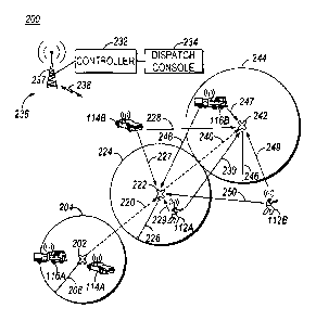
serving fixed terminals. Sites of neighboring fixed terminals may be offset
from one
another and may be non-overlapping or partially or fully overlapping with one
another.
In another example, SUs may communicate within a network without the
assistance of
one or more infrastructure equipment (e.g., base stations or repeaters), in a
mode called
direct mode. For example, in direct mode, SUs may transmit asynchronously and
SUs s
within range of the transmission synchronize themselves to that transmission
for the
purposes of receiving the transmission, but any transmissions in response to
or after the
first transmission are transmitted asynchronously.
[00021
RANs may operate according to any one of a number of available
industry standard protocols such as, for example, an open media alliance (OMA)
push
to talk (PTT) over cellular (OMA-PoC) standard, a voice over IP (VoIP)
standard, or a
PTT over IP (PoIP) standard. Typically, protocols such as PoC, VoIP, and PoIP
are
implemented over broadband RANs including third generation and fourth
generation
networks such as third generation partnership project (3GPP) Long Term
Evolution
(LTE) networks.
[0003]
RANs may additionally or alternatively operate according to an
industry standard land mobile radio (LMR) protocol such as, for example, the
Project
CA 02943516 2016-09-21
WO 2015/147670 PCT/RU2014/000186
2
25 (P25) standard defined by the Association of Public Safety Communications
Officials International (APCO), or other radio protocols, the Terrestrial
Trunked Radio
(TETRA) standard defined by the European Telecommunication Standards Institute
(ETSI), the Digital Private Mobile Radio (dPMR) standard also defined by the
ETSI, or
the Digital Mobile Radio (DMR) standard also defined by the ETSI. Because
these
systems generally provide lower throughput than the 3GPP and LTE systems, they
are
sometimes designated narrowband RANs.
[0004]
Communications in accordance with any one or more of these
protocols or standards, or other protocols or standards, may take place over
physical
channels in accordance with one or more of a TDMA (time division multiple
access),
FDMA (frequency divisional multiple access), OFDMA (orthogonal frequency
division
multiplexing access), or CDMA (code division multiple access) protocols.
Subscriber
units in RANs such as those set forth above send and receive audio and/or data
(e.g.,
encoded voice, audio, video, control information, data, and/or audio/video
streams) in
accordance with the designated protocol.
[0005] OMA-
PoC, in particular, enables familiar PTT and "instant on"
features of traditional half duplex SUs, but uses SUs operating over modem
cellular
telecommunications networks. Using PoC, SUs such as mobile telephones and
notebook computers can function as PTT half-duplex SUs for transmitting and
receiving auditory data. Other types of PTT models and multimedia call models
(MMCMs) are also available.
[0006]
Floor control in an OMA-PoC session is generally maintained by a
PTT server that controls communications between two or more SUs. When a user
of
one of the SUs keys a PTT button, a request for permission to speak in the OMA-
PoC
session is transmitted from the user's SU to the PTT server using, for
example, a real-
time transport protocol (RTP) message. If no other users are currently
speaking in the
PoC session, an acceptance message is transmitted back to the user's SU and
the user
can then speak into a microphone of the SU. Using standard
compression/decompression (codec) techniques, the user's voice is digitized
and
transmitted using discrete auditory data packets (e.g., together which form an
auditory
data stream over time), such as according to RTP and interne protocols (IP),
to the
PTT server. The PTT server then transmits the received auditory data packets
to other
CA 02943516 2016-09-21
WO 2015/147670 PCT/RU2014/000186
3
users of the PoC session (e.g., to other SUs in the group of SUs or talkgroup
to which
the user is subscribed), using for example a unicast, multicast, or broadcast
communication technique.
[0007]
Narrowband LMR systems, on the other hand, operate in either a
conventional or trunked configuration. In either configuration, a plurality of
SUs are
partitioned into separate groups of SUs. In a conventional system, each SU in
a group is
selected to a particular frequency for communications associated with that
SU's group.
Thus, each group is served by one channel, and multiple groups may share the
same
single frequency (in which case, in some embodiments, group IDs may be present
in
the group data to distinguish between groups using the same shared frequency).
Communications in a conventional system may take place via an infrastructure-
provided repeater or repeaters, or directly via a direct mode (including talk-
around)
protocol.
[0008] In
contrast, a trunked radio system and its SUs use a pool of traffic
channels for virtually an unlimited number of groups of SUs (e.g.,
talkgroups). Thus,
all groups are served by all channels. The trunked radio system works to take
advantage
of the probability that not all groups need a traffic channel for
communication at the
same time. When a member of a group requests a call on a control or rest
channel on
which all of the SUs in the system idle awaiting new call notifications, in
one
embodiment, a call controller assigns a separate traffic channel for the
requested group
call, and all group members move from the assigned control or rest channel to
the
assigned traffic channel for the group call. Communications then take place
via the
assigned traffic channel repeater. In another embodiment, when a member of a
group
requests a call on a control or rest channel, the call controller may convert
the control
or rest channel on which the SUs were idling to a traffic channel for the
call, and
instruct all SUs that are not participating in the new call to move to a newly
assigned
control or rest channel selected from the pool of available channels. With a
given
number of channels, a much greater number of groups can be accommodated in a
trunked system as compared with conventional radio systems. In a trunked
system,
communications may also take place directly between SUs when operating in a
talk-
around mode (e.g. direct mode when infrastructure devices are also available).
[0009]
Group calls may be made between wireless and/or wireline
CA 02943516 2016-09-21
WO 2015/147670 PCT/RU2014/000186
4
participants in accordance with either a narrowband or a broadband protocol or
standard. Group members for group calls may be statically or dynamically
defined.
That is, in a first example, a user or administrator working on behalf of the
user may
indicate to the switching and/or radio network (perhaps at a radio controller,
call
controller, PTT server, zone controller, or mobile management entity (MME),
base
station controller (BSC), mobile switching center (MSC), site controller, Push-
to-Talk
controller, or other network device) a list of participants of a group at the
time of the
call or in advance of the call. The group members (e.g., SUs) could be
provisioned in
the network by the user or an agent, and then provided some form of group
identity or
identifier, for example. Then, at a future time, an originating user in a
group may cause
some signaling to be transmitted indicating that he or she wishes to establish
a
communication session (e.g., group call) with each of the pre-designated
participants in
the defined group. In another example, SUs may dynamically affiliate with a
group
(and also disassociate with the group) perhaps based on user input, and the
switching
and/or radio network may track group membership and route new group calls
according
to the current group membership. In some instances, a group of SUs may be
identified
as a talkgroup, and a call initiated to members of that talkgroup (whether
including the
transmission of audio and/or data and/or video to a group of target SUs) may
be a
identified as a talkgroup call.
[0010] One problem
that has arisen with the use of talkgroups to distribute
auditory or other data to member SUs is that a situation may arise where an
incident
occurs or a response is otherwise required at a movable location, and a
responder may
wish to dynamically create a location-based talkgroup relative to that movable
location
so that responding personnel may communicate with one another and coordinate a
response and/or intercept between them. For example, a movable location may
refer to
a suspect or victim who is moving on foot or via motor vehicle and a responder
may
wish to create a location-based talkgroup for use in tracking or intercepting
the suspect
or victim, among other possibilities. Existing methods of dynamically creating
such a
location-based talkgroup have relied upon pre-configured static distances from
the
initially defined location (such as the location of the criminal action or
injury) to
determine which responding personnel (and corresponding SUs) should be
included in
the location-based talkgroup.
CA 02943516 2016-09-21
WO 2015/147670 PCT/RU2014/000186
[0011] For
example, as shown in FIG. 1, an incident/response area 100 may
include a movable incident scene that begins at an initial defmed location
102, and then
moves to a first subsequent location 122, and then moves to a second
subsequent
location 142. The movable incident scene may be associated with, for example,
a
5 suspect
that is involved in an initial transgression at initial defined location 102,
and
then moves away from the initial defined location 102 on foot or in a motor
vehicle to
the subsequent locations 122, 142.
[0012] The
initial defined location 102 may be reported by a responder on
scene or set by a dispatcher at a dispatch console 134, and, as is known, may
be
assigned a response boundary 104 statically defined at a fixed distance 106
from the
initial defined location 102. Various potential responding SUs (each of which
may also
already be a member of a corresponding incident response group, such as
police, fire,
or traffic control) may already be on scene or within the response boundary
104 at the
time of the incident. Each potential responder may be a person or vehicle with
an
associated SU (e.g., portable or vehicular SU) capable of communicating
wirelessly
with each other and/or with a RAN 136. Such potential responding SUs may
include,
for example, a motor vehicle potential responding SU 114A (e.g., police car)
and a
motor vehicle potential responding SU 116A (e.g., fire engine). Other
potential
responding SUs may fall within incident/response area 100 but outside of the
response
boundary 104; including for example, pedestrian potential responding SUs 112A
and
112B, motor vehicle potential responding SU 114B, and motor vehicle potential
responding SU 116B.
[0013]
Each of the pOtential responding SUs may, in one example, already
be actively using RF resources 128 of the RAN 136, which may be a LMR or LTE
RAN providing coverage substantially throughout the incident/response area
100,
illustrated in FIG. 1 as including a single fixed terminal 130 coupled to a
controller 132
(e.g., radio controller, call controller, PTT server, zone controller, MME,
BSC, MSC,
site controller, Push-to-Talk controller, or other network device) and via the
controller
132, to a dispatch console 134.
[0014] As
illustrated in FIG. 1, using the statically defined response
boundary 104 to dynamically set a location-based group membership for an
incident or
response required at or near the initial defined location 102 may cause some
potential
CA 02943516 2016-09-21
WO 2015/147670 PCT/RU2014/000186
6
responding SUs (motor vehicle SUs 114A and 116A, in this example) to be
included in
the location-based group, but may fail to include some potential responding
SUs in the
location-based group that should be, perhaps based on an anticipated or
predicted
movement of the movable incident scene to subsequent locations 122, 142.
Pedestrian
potential responding SUs 112A, 112B, motor vehicle SU 114B, and/or motor
vehicle
SU 116B, for example, may be capable of intercepting or otherwise responding
to the
movable incident scene at or near subsequent locations 122 and/or 142, but in
existing
systems, they are not included in the location-based group.
[0015]
Accordingly, for this and other reasons, there is a need for an
improved method and apparatus for dynamically forming location-based groups
for
movable incident scenes so that incident and other types of response groups
can be
created more efficiently and can collaborate and coordinate a response to a
moving
incident scene more effectively.
Brief Description of the Several Views of the Drawings
[0016] The
accompanying figures, where like reference numerals refer to
identical or functionally similar elements throughout the separate views,
together with
the detailed description below, are incorporated in and form part of the
specification,
and serve to further illustrate embodiments of concepts that include the
claimed
invention, and explain various principles and advantages of those embodiments.
[0017] FIG. 1 is a
schematic diagram of an existing incident/response area
illustrating issues that may arise when creating location-based groups for a
movable
incident scene.
[0018] FIG.
2 is a schematic diagram of a first incident/response area
illustrating dynamic location-based group formation for movable incident
scenes in
accordance with an embodiment.
[0019] FIG.
3 is a schematic diagram of a second incident/response area
illustrating dynamic location-based group formation for movable incident
scenes in
accordance with a further embodiment.
[0020] FIG.
4 is a block diagram of a controller device capable of
dynamically forming location-based groups for movable incident scenes in
accordance
with an embodiment.
[0021] FIG.
5 is a flow chart illustrating processing steps executable at the
CA 02943516 2016-09-21
WO 2015/147670 PCT/RU2014/000186
7
controller devices of FIGs. 2, 3, or 4 for dynamically forming location-based
groups for
movable incident scenes in accordance with several embodiments.
[0022]
Skilled artisans will appreciate that elements in the figures are
illustrated for simplicity and clarity and have not necessarily been drawn to
scale. For
example, the dimensions of some of the elements in the figures may be
exaggerated
relative to other elements to help to improve understanding of embodiments of
the
present invention.
[0023] The
apparatus and method components have been represented where
appropriate by conventional symbols in the drawings, showing only those
specific
details that are pertinent to understanding the embodiments of the present
invention so
as not to obscure the disclosure with details that will be readily apparent to
those of
ordinary skill in the art having the benefit of the description herein.
Detailed Description of the Invention
[0024]
Disclosed is an improved method and apparatus for dynamically
forming location-based groups for movable incident scenes so that incident and
other
types of response groups can be created more efficiently and can collaborate
and
coordinate a response to a moving incident scene more effectively.
[0025] In
one embodiment, dynamic location-based group formation is
provided for a movable incident scene in a wireless radio communication system
comprising a plurality of first subscriber units. A controller receives, from
one of a
second subscriber unit and a dispatch console, a request for a new group call
for a
movable incident scene. The controller also receives an initial location
associated with
the movable incident scene and an indication of a speed and direction of
travel
associated with the movable incident scene. The controller determines, as a
function of
the initial location and the indication of the speed and direction of travel
associated
with the movable incident scene, one or more potential future locations of the
movable
incident scene different from the initial location, and identifies a set of
one or more
inclusion threshold rules for each of the one or more potential future
locations. The
controller then forms a location-based group including first subscriber units
meeting at
least one inclusion threshold rule in the respective identified set of
inclusion threshold
rules for any one of the one or more potential future locations. Once formed,
the
controller causes one or more of audio and data transmitted by the one of the
second
CA 02943516 2016-09-21
WO 2015/147670 PCT/RU2014/000186
8
subscriber unit and the dispatch console to be provided to the first
subscriber units in
the formed group.
[0026] In
another embodiment, a controller for providing dynamic location-
based group formation for a movable incident scene includes a transceiver, a
data store,
and one or more processors configured to: receive, via the transceiver and
from one of a
second subscriber unit and a dispatch console, a request for a new group call
for a
movable incident scene; receive, via the transceiver, an initial location
associated with
the movable incident scene and an indication of a speed and direction of
travel
associated with the movable incident scene; determine, as a function of the
initial
location and the indication of the speed and direction of travel associated
with the
movable incident scene, one or more potential future locations of the movable
incident
scene different from the initial location; identify a set of one or more
inclusion
threshold rules for each of the one or more potential future locations; form,
by the
controller, a location-based group including first subscriber units meeting at
least one
inclusion threshold rule in the respective identified set of inclusion
threshold rules for
any one of the one or more potential future locations; and cause, via the
transceiver,
one or more of audio and data transmitted by the one of the second subscriber
unit and
the dispatch console to be provided to the first subscriber units in the
formed group.
[0027]
Each of the above-mentioned embodiments will be discussed in more
detail below, starting with example incident/response area schematic diagrams
of areas
in which the embodiments may be practiced, followed by an illustration of
devices and
processing steps for supporting dynamic location-based group formation for
movable
incident scenes from an infrastructure controller device perspective. Further
advantages
and features consistent with this disclosure will be set forth in the
following detailed
description, with reference to the figures.
[0028] 1.
Example Incident/Response Areas and Location-Based
Group Membership Determinations for Movable Incident Scenes
[0029]
FIGs. 2 and 3 are schematic diagrams of first and second
incident/response areas illustrating dynamic location-based group formation
for
movable incident scenes in accordance with several embodiments. Where similar
reference characters are used across FIGs. 2 and 3, their description is not
repeated, but
is intended to equally apply to the other figures in which they appear. While
FIGs. 2
CA 02943516 2016-09-21
WO 2015/147670 PCT/RU2014/000186
9
and 3 illustrate a single radio access network (RAN), single fixed terminal,
single
radio-frequency (RF) resource, a particular arrangement and quantity of
initial and
subsequent locations, and a particular arrangement, quantity, and types of
potential
responders (and their associated SUs), such illustrations are exemplary in
nature only,
and in other embodiments, different arrangements and quantities of elements
may be
employed.
[0030]
FIG. 2, in particular, illustrates an example first incident/response
area 200 including a RAN 236, an initial defined location 202 associated with
a
movable incident scene, movable incident scene potential (e.g., predicted)
future
locations 222, 242, and a plurality of potential responding SUs 112A, 112B,
114A,
114B, 116A, and 116B. The movable incident scene may again, for example, be
related
to an identified suspect of a crime and/or someone or something related to an
identified
suspect, to a victim of a crime and/or someone or something related to an
identified
suspect, to a motor vehicle that presents a hazard to its surroundings, or any
other
location, person, or thing that is movable but at which a response or
intercept is
required.
[0031] The
wireless resource 238 may be, for example, one or more wireless
links supporting a standard or protocol such as GPRS or UMTS, 2G (e.g. GSM),
3G
(e.g. WCDMA or Long Term Evolution (LTE)), 4G (WiMAX or LTE), iDEN, wireless
LAN (WLAN), ETSI Digital Mobile Radio (DMR), Project 25 (P25) standard defined
by the Association of Public Safety Communications Officials International
(APCO),
Terrestrial Trunked Radio (TETRA), or other radio protocols or standards.
[0032]
Each potential responding SU may be a group communications
device, such as a push-to-talk (PTT) device, that is normally maintained in a
monitor
only mode, and which switches to a transmit-only mode (for half-duplex
devices) or
transmit and receive mode (for full-duplex devices) upon depression or
activation of a
PTT input switch. The group communications architecture provided via RAN 236
allows a single responding SU, such as responding SU 114A, to communicate with
one
or more members associated with a dynamically formed location-based talkgroup
at the
same time.
[0033]
Although only one controller 232 is illustrated in FIG. 2, a distributed
controller may be used that divides functions across multiple devices, perhaps
for load
CA 02943516 2016-09-21
WO 2015/147670 PCT/RU2014/000186
balancing reasons. Controller 232 may additionally function as a call
controller, PTT
server, zone controller, mobile management entity (MME), base station
controller
(BSC), mobile switching center (MSC), site controller, Push-to-Talk
controller, or
other network device for aiding in the control and/or distribution of group
auditory data
5 or
other types of group communications amongst responding SUs. Finally, and
although not illustrated in FIG. 2, RAN 236 may further comprise one or more
additional routers, switches, LANs, WLANs, WANs, access points, or other
network
infrastructure.
[0034]
External networks (not shown) may also be accessible to potential
10
responding SUs and dispatch console 234 via RAN 236. External networks may
include, for example, a public switched telephone network (PSTN), a plain old
telephone system (POTS), the Internet, or another wireless service provider's
network,
among other possibilities.
[0035]
Dispatch console 234 may be directly coupled to controller 232, as
shown, or may be indirectly coupled to controller 232 via one or more internal
or
externals networks. The dispatch console 234 allows an administrator or
dispatcher at
the dispatch console 234 to initiate infrastructure-sourced dynamic location-
based
group communications to groups of responding SUs relative to a movable
incident
scene indicated by the dispatcher, among other features and functions.
[0036] RAN 236 in
FIG. 2, similar to FIG. 1, provides wireless
communications services to all potential responding SUs in the
incident/response area
200 via fixed terminal 237 and wireless resource 238. RAN 236 provides a
communications path between controller 232 and potential responding SUs in the
incident/response area 200, among other provided functions and services.
[0037] The initial
defined location 202 of the movable incident scene is
provided to the controller 232 and may be entered in or reported manually by a
first
responder on-scene (for example, motor vehicle potential responding SU 114A in
FIG.
2), could be automatically determined by a determined location of some other
responding SU that is at the initial defined location 202 (not illustrated in
FIG. 2), or
could be set by a dispatcher at a dispatch console 234 communicatively coupled
to the
controller 232 (e.g., after receiving a report from a potential responding SU
or via some
other mechanism, such as a POTS system call received at the dispatch console
234). In
CA 02943516 2016-09-21
WO 2015/147670 PCT/RU2014/000186
11
other examples, the initial defined location 202 could be provided to the
controller 232,
directly or indirectly, by the movable incident scene itself such as, for
example, by a
reported GPS location or triangulated position of a mobile phone associated
with a
person or vehicle defining the movable incident scene, or by a reported GPS
location or
triangulated position of a tracking device associated with a person or vehicle
defining
the movable incident scene. In still further embodiments, a plurality of fixed
terminals
(not shown) in the radio access network 236 may be used to determine a
location, by
the infrastructure and using triangulation of a signal emitted from a mobile
device,
tracking device, or other wireless transmitter defining or associated with the
movable
incident scene, of the movable incident scene.
[0038] In addition to the initial defined location 202 of the
movable incident
scene, indication(s) of a speed and direction of travel of the movable
incident scene is
obtained by, and/or provided to, the controller 232. For example, a speed and
direction
of travel of the movable incident scene may be entered in or reported manually
by a
first responder on-scene (again, for example, by motor vehicle potential
responding SU
114A in FIG. 2), could be automatically determined by a determined or reported
speed
and direction of travel of a responding SU that is associated with the movable
incident
scene (e.g., a police car tailing a suspect in a motor vehicle or a pedestrian
officer
chasing a suspect on foot, for example), or could be set by a dispatcher at a
dispatch
console 234 communicatively coupled to the controller 232 (e.g., after
receiving a
report from a potential responding SU or via some other mechanism, such as a
POTS
system call received at the dispatch console 234, indicating an estimated or
actual
speed and direction of travel of the movable incident scene). In other
examples, the
indication of speed and direction of travel of the movable incident scene
could be in the
form of a plurality of reported sequential GPS locations or triangulated
positions of a
mobile phone or other wireless device defining or associated with the movable
incident
scene (from which the controller may extract and/or determine speed and
direction
information from using a time different between the location determination,
such as
times of receipt or location messages or differences in time stamps of the
initial
location determination), or by a plurality of reported sequential GPS
locations or
triangulated positions of a potential responding SU associated with the
movable
incident scene (again, from which the controller may extract and/or determine
speed
CA 02943516 2016-09-21
WO 2015/147670 PCT/RU2014/000186
12
and direction information from using location and time differences). In still
further
embodiments, a plurality of fixed terminals in the radio access network 236
may be
used to determine a plurality of locations, by the infrastructure and using
triangulation
of a signal emitted from a mobile device or other wireless transmitter
associated with
the movable incident scene, of the movable incident scene or a device
associated with
the movable incident scene, from which the controller may similarly extract
and/or
determine speed and direction information. In some embodiments, the initial
location
and a single subsequent location of the movable incident scene may be
sufficient for
the controller to determine a speed and direction of travel. In other
embodiments, a
minimum threshold plurality of locations (e.g., more than two) of the movable
incident
scene may be obtained prior to estimating a speed and direction of travel of
the
movable incident scene.
[0039] In
still another embodiment, movement sensors (such as an
accelerometer, magnetometer, and/or gyroscope) may be provided on the movable
incident scene or a device associated with the movable incident scene, and
sensor
information provided to the controller 232 as indications of speed and/or
direction,
perhaps accompanying other information, allowing the controller to determine
the
speed and direction of movement of the movable incident scene. An
accelerometer is a
device that measures acceleration. Single- and multi-axis models are available
to detect
magnitude and direction of the acceleration as a vector quantity, and can be
used to
sense orientation, acceleration, vibration shock, and falling. A gyroscope is
a device for
measuring or maintaining orientation, based on the principles of conservation
of
angular momentum. One type of gyroscope, a microelectromechanical system
(MEMS)
based gyroscope, uses lithographically constructed versions of one or more of
a tuning
fork, a vibrating wheel, or resonant solid to measure orientation. Other types
of
gyroscopes could be used as well. A magnetometer is a device used to measure
the
strength and/or direction of the magnetic field in the vicinity of the device,
and can be
used to determine a direction in which a person or device is facing. Other
types of
movement sensors could additionally, or alternatively, be used as well.
[0040] Once the
controller 232 has information including the initial defined
location 202 of the movable incident scene and an indication of a speed and
direction of
movement of the movable incident scene, the controller can calculate one or
more
CA 02943516 2016-09-21
WO 2015/147670 PCT/RU2014/000186
13
predicted (e.g., potential) future locations of the movable incident scene
using a pre-
configured algorithm or algorithms pre-configured at the controller and/or
identified by
a dispatcher or potential responding SU in the field. For example, the
algorithm may
use the determined initial defined location and known speed and direction of
movement
of the movable incident scene to extrapolate future locations of the movable
incident
scene at time increments such as 1, 5, 10,15, and/or 30 minute increments, or
at similar
integer or decimal increments. In other embodiments, the algorithm may use the
determined initial defined location and known speed and direction of movement
of the
movable incident scene to extrapolate future locations of the movable incident
scene at
distance increments such as 1, 5, 10,15, and/or 30 mile increments, or at
similar integer
or decimal increments. Increment values and the number of potential future
locations to
consider could be pre-configured at the controller 232, or. specified by a
dispatcher via
dispatch console 234 or specified by a potential responding SU, such as by the
initiator
of the request for the location-based group call.
[0041] In the
example set forth in FIG. 2, the movable incident scene
identified initially at defined location 202 and whose speed and direction of
travel is
reported to or otherwise determined by controller 232, is predicted to move
along path
220 to a first potential future location 222 and then along path 240 to second
potential
future location 242. While in this example, only two potential future
locations are
illustrated and both are along a same or similar path, in other examples, more
than two
potential future locations could be predicted by the controller 232, and
potential future
locations may occur across a combination of various parallel and/or serial
paths, as will
be explained in more detail with respect to FIG. 3 below. The potential future
locations
222, 242 could be set using pre-configured intervals set at the controller
232, or via
some other method. For example, first potential future location 222 may be set
5 miles
or 10 minutes away from (given the known speed and direction of travel of the
movable
incident scene) the initial location 202, and second potential future location
242 may be
set 5 miles or 10 minutes away from (given the known speed and direction of
travel of
the movable incident scene) the initial defined location 222.
[0042] Once one or
more potential future locations are identified by the
controller 232, the controller 232 identifies a set of one or more inclusion
threshold
rules for each of the one or more potential future locations. The set of
inclusion
CA 02943516 2016-09-21
WO 2015/147670 PCT/RU2014/000186
14
threshold rules for each of the one or more potential future locations
determines which,
if any, potential responding SUs in incident/response area 200 should be
included in a
location-based response group for the movable incident scene. Same or
different sets of
inclusion threshold rules could be applied to each of the one or more
potential future
locations.
[0043] For
example, an inclusion threshold rule in the set of rules associated
with a particular potential future location may identify potential responding
SUs having
current locations that fall within a maximum response distance associated with
and
relative to the particular potential future location. Same or different
maximum response
distances may be associated with each of the one or more potential future
locations of
the movable incident scene. For example, in some embodiments, the maximum
response distance is increased as a distance between the initial defined
location and the
particular potential future location is increased. Furthermore, even for a
same potential
future location, different maximum response distances may be applied depending
on a
type of responder for responding to the potential future location. For
example, a first
maximum distance criterion may be applied at the particular potential future
location
for potential responding SUs associated with a pedestrian mode of transport, a
second
larger maximum distance criterion may be applied at the particular potential
future
location for potential responding SUs associated with a human-powered vehicle
mode
of transport (e.g., bicycle), and a third still larger maximum distance
criterion may be
applied at the particular potential future location for potential responding
SUs
associated with a motor vehicle mode of transport. Each of the applied first,
second,
and third maximum distance criterions may similarly get larger as the distance
between
the initial defined location and the particular potential future location
increases.
[0044] Controller
232 may also store, or have access to, current location
information for each of the potential responding SUs in the incident/response
area 200.
Current location information may be determined by each responding SU
independently
using a Global Navigation Satellite System receiver such as a GPS receiver or
using a
trilateration technique via signals received from a plurality of ground-based
fixed
terminals and then reported to a location server (at the controller 232 or
elsewhere
internal or external to the RAN 236) on a regular or intermittent schedule.
Additionally
or alternatively, an infrastructure-based location determination may be
implemented
CA 02943516 2016-09-21
WO 2015/147670 PCT/RU2014/000186
using same or similar trilateration techniques via signals received from the
potential
responding SU at a plurality of ground-based fixed terminals. Still further,
the current
location of each of the SUs may be requested in response to receiving the
request for a
new location-based group call for a movable incident scene. This may include,
for
5
example, the controller causing requests for current location information to
be
transmitted to each of the potential responding SUs and subsequently
receiving, in
response, current location information from each of the potential responding
SUs.
Other possibilities exist as well.
[0045] The
controller 232 may determine or have access to current location
10
information for all potential responding SUs active and/or known to the
controller 232,
a subset of all potential responding SUs active and/or known to the controller
232
including those currently registered with one or more RANs providing wireless
service
at the initial or potential future locations or in a threshold maximum region
surrounding
the initial or potential future locations such as 1-5 miles, a subset of all
potential
15
responding SUs active and/or known to the controller 232 including only those
that are
not already active in another call or otherwise determined to be busy, for
example, or a
subset of all potential responding SUs active and/or known to the controller
232 that
are particularly identified as available for participating in dynamically
created location-
based talkgroups, among other possibilities.
[0046] FIG. 2
illustrates an example application of maximum distance
inclusion threshold rules to first and second potential future locations 222
and 242. In
particular, a first perimeter 224 is defined at a distance 226 from the first
potential
future location 222 and a second perimeter 244 is defined at a distance 246
from the
second potential future location 242. While each of the perimeters 224, 244
are
illustrated as circles centered on their respective potential future location,
in other
embodiments, the perimeters may be based on some other form of cartographic
definition, such as a set of three or more polygon vertices, where each
polygon vertex is
a GPS coordinate, such as a latitude and longitude pair, or some other form of
cartographic definition, having a center at the defined location or slightly
offset from
the defined location. Other examples are possible as well.
[0047] As
illustrated in FIG. 2, pedestrian potential responding SU 112A
falls within perimeter 224 and motor vehicle potential responding SU 116B
falls within
CA 02943516 2016-09-21
WO 2015/147670 PCT/RU2014/000186
16
perimeter 244, thus meeting the respective distance-based inclusion threshold
rules for
the first and second potential future locations 222 and 242. Assuming that
motor
vehicle potential responding SU 114A is the initiating/requesting device
requesting,
itself or via dispatch console 234, a location-based group call be initiated
for a movable
incident scene associated with initial defined location 202, the controller
232 would
create a location-based group including motor vehicle potential responding SU
114A as
the initiator/requestor SU, pedestrian potential responding SU 112A as meeting
the
respective distance-based inclusion threshold rule for first potential future
location 222,
and motor vehicle potential responding SU 116B as meeting the respective
distance-
based inclusion threshold rule for second potential future location 242.
[0048] In
some embodiments, the controller 232 may cause to be transmitted
an instruction (such as a text message, control signal, and/or location
indication) to
each potential responding SU meeting a respective distance-based inclusion
threshold
rule for a particular potential future location that instructs the potential
responding SU
to travel to the determined one of the potential future locations with which
they met the
inclusion threshold rule. For example, in this case, the controller 232 may
cause to be
transmitted an instruction to pedestrian potential responding SU 112A meeting
the
respective distance-based inclusion threshold rule for first potential future
location 222
to proceed to the first potential future location 222 to intercept the movable
incident
scene.
[0049] In
those situations where a potential responding SU has a current
location falling within more than one perimeter associated with more than one
potential
future location, the controller 232 may include the potential responding SU in
the
location-based group, and may also make a further determination of which
potential
future location the potential responding SU could arrive at first (e.g.,
lowest absolute
arrival time) or arrive at quickest (e.g., lowest overall travel time) from
its current
location and transmit an instruction (such as a text message, control signal,
and/or
location indication) instructing the potential responding SU to travel to the
determined
one of the potential future locations. For example, assuming the current time
is 10:00,
and a potential responding SU could respond at a potential future location A
of the
movable incident scene at 10:10 (e.g., 10 minute travel time to arrive to
location A) and
could also respond at a potential future location B of the movable incident
scene at
CA 02943516 2016-09-21
WO 2015/147670 PCT/RU2014/000186
17
10:05 (e.g., 5 minute travel time to location B), and where the movable
incident is
estimated to arrive at location A at 10:15 and location B at 10:20, in some
embodiments, the earlier interception time / absolute arrival time would be
preferred at
potential future location A (10:10), even though it would take the potential
responding
SU longer to travel to that location. In other embodiments, the lower travel
time could
be preferred at potential future location B (10:05), even though the movable
incident
scene isn't actually predicted to arrive there until 10:20. Other
possibilities exist as
well.
10050] In
addition to the set(s) of inclusion threshold rules applied to the one
or more potential future locations 222, 242, a same or different set of
inclusion
threshold rules could also be applied to the initial defined location 202 for
identifying
potential responding SUs for inclusion in the location-based group for
responding to
the movable incident scene. For example, the set of inclusion threshold rules
for the
initial defined location 202 may include a distance-based inclusion threshold
rule that
considers potential responding SUs having current locations that fall within a
maximum
response distance associated with and relative to the initial defined location
202 of the
movable incident scene. For example, and with respect to FIG. 2, a third
perimeter 204
is defined at a distance 206 from the initial defined location 202 formed via
a same or
similar manner as the first and second perimeters 224 and 244 set forth above.
[0051] As
illustrated in FIG. 2, motor vehicle potential responding SU 116A
falls within perimeter 204, thus meeting the respective inclusion threshold
rule for the
initial defined location 202. Assuming that motor vehicle potential responding
SU
114A was the initiating/requesting device requesting, itself or via dispatch
console 234,
a location-based group call be initiated for a movable incident scene
associated with
initial defined location 202, the controller would create a location-based
group
including motor vehicle potential responding SUs 114A and 116A, pedestrian
potential
responding SU 112A, and motor vehicle potential responding SU 116B.
[0052] In
embodiments in which the initial defined location 202 is not
considered in determining which potential responding SUs to add to the
location-based
group, individual responding SUs, such as a location-based group call
requesting SU
that may not meet the inclusion threshold rule(s) for any one or more of the
potential
future locations may still be added to the location-based group by the
controller 232. Of
CA 02943516 2016-09-21
WO 2015/147670 PCT/RU2014/000186
18
course, a dispatcher operating dispatch console 232 could further manually add
additional potential responding SUs to the location-based group for the
movable
incident scene automatically created by controller 232.
[0053] In
another embodiment, an inclusion threshold rule in the set of rules
associated with a particular potential future location may identify potential
responding
SUs having an estimated arrival time Ts9 at the particular potential future
location that
occurs earlier than an estimated arrival time Ti, of the movable incident
scene at the
particular potential future location. For example, and with respect to FIG. 2,
an
estimated arrival time T,si of the movable incident scene at first potential
future
location 222 and an estimated arrival time T192 of the movable incident scene
at second
potential future location 242 could be determined by the controller 232 using
the initial
defined location 202 and the determined direction and speed of the movable
incident
scene. The estimated arrival times T191 and T192 could be an amount of travel
time
remaining until the movable incident scene arrives at each respective
potential future
location 222, 242, and could decrement as time moves forward, or could take
the form
of an absolute arrival time for each location, among other possibilities.
Therefore, a
comparison of estimated arrival times could involve comparing absolute arrival
times
of potential responding SUs and the movable incident scene to determine which
occurs
earlier than the other, or comparing travel times of potential responding SUs
and the
-- movable incident scene to determine which is smaller (and thus earlier)
than the other.
[0054] Once
the estimated arrival times of the movable incident at each of
the one or more potential future locations is known, arrival times for each of
the
potential responding SUs in the incident/response area 200 can be calculated
relative to
each of the potential future locations. Arrival times for each of the
potential responding
SUs could be based on a current location and mode of transport associated with
each
potential responding SU, on a current location and determined instantaneous or
average
velocity of each potential responding SU, or via some other mechanism. For
example,
and with respect to FIG. 2, estimated arrival times T. 227 and Ts. 228 of the
motor
vehicle potential responding SU 114B at each of the first potential future
location 222
and second potential future location 242, based on its current location and
one or more
of its mode of transport and average or instantaneous detected velocity, could
be
determined by the controller 232 or otherwise provided to the controller 232
via some
CA 02943516 2016-09-21
WO 2015/147670 PCT/RU2014/000186
19
other infrastructure device. Similarly, estimated arrival times T990 229 and
T. 230 of
the pedestrian potential responding SU 112A at each of the first potential
future
location 222 and second potential future location 242, based on its current
location and
one or more of its mode of transport and average or instantaneous detected
velocity,
could be determined by the controller 232 or otherwise provided to the
controller 232
via some other infrastructure device. Estimated arrival times T. 247 and T.
248 of
the motor vehicle potential responding SU 116B and estimated arrival times T.
249
and T. 250 of the pedestrian potential responding SU 112B could be similarly
determined.
[0055] In one
embodiment, a plurality of reported locations for a potential
responding SU may be used by the controller 232 to determine an average or
instantaneous speed associated with that potential responding SU and/or a
direction of
travel of the potential responding SU, and the controller 232 may use such
information
directly to determine an ability to meet an arrival time inclusion threshold
rule or may
use such information indirectly in determining a mode of transport associated
with the
potential responding SU (which may then be used to determine an ability to
meet an
arrival time inclusion threshold rule).
[0056] In
some embodiments, mode of transport information may be
obtained by the controller 232 via a potential responding SU ID to mode of
transport
mapping stored at the controller 232 or made available to the controller at
some other
device located within the RAN 236 or external to the RAN 236. Once the mode of
transport information is retrieved for each of the potential responding SUs,
average or
maximum speed capability information associated with each mode of transport
may be
retrieved via a mode of transport to speed mapping. Once the speed capability
information and current location information is known for a potential
responding SU,
the controller 232 can determine an estimated arrival time for the potential
responding
SU to each of the potential future locations fur use in determining whether
the potential
responding SU meets the arrival-time-based inclusion threshold rule for any
one or
more potential future locations.
[0057] In some
embodiments, updates to a mode of transport may be
received at the controller 232 from a potential responding SU that changes a
mode of
transport associated with the potential responding SU from one mode of
transport to
CA 02943516 2016-09-21
WO 2015/147670 PCT/RU2014/000186
another different mode of transport. The controller 232 may responsively
update the
mapping at the controller 232 itself or cause an update to be made at some
other device
located within the same RAN 236 as the controller or at some device external
to the
RAN 236 that stores the SU ID to mode of transport mapping for the potential
5 responding SU.
[0058] As set forth with respect to the estimated arrival times
T1s1 and Tia,
the respective estimated arrival times T. of the potential responding SUs
could
similarly be an estimated travel time it would take for the potential
responding SU to
reach each respective potential future location 222, 242, or could take the
form of an
10 estimated absolute arrival time for each location, among other
possibilities.
[0059] Once the estimated arrival times Tõu of each of the
potential
responding SUs in the incident/response area 200 for each determined potential
future
location of the movable incident scene are known, the controller 232 can
compare them
to the estimated arrival times of the movable incident scene (in this case,
T1s1 and T192)
15 and determine whether each of the potential responding SUs is capable of
arriving at
one or more of the potential future locations prior to or substantially at a
same time as
the movable incident scene. For example, assuming the current time is 10:00
pm, if the
estimated arrival time T.1 of the movable incident scene at the first
potential future
location 222 is 9 minutes from now(travel time) or 10:09 pm (absolute time)
and the
20 estimated arrival time T192 of the movable incident scene at the second
potential future
location 242 is 19 minutes from now (travel time) or 10:19 pm (absolute time),
the
controller may determine to include motor vehicle responder 114B in the
location-
based group if either one of its estimated arrival times T. 227 or 228 at the
potential
future locations 222, 242 occurs prior to (e.g., absolute time earlier than or
travel time
less than) the respective arrival time T191 or T192 of the movable incident
scene at that
same potential future location. In this case, if the motor vehicle potential
responding
SU 114B, based on its current location and its determined speed (average or
instantaneous) or estimated speed (perhaps based on its associated mode of
transport) is
estimated by the controller to arrive at the first potential future location
222 prior to
10:09 pm or within 9 minutes, or if the motor vehicle potential responding SU
114B is
estimated by the controller to arrive at the second potential future location
242 prior to
10:19 pm or within 19 minutes, the motor vehicle potential responding SU 114B
would
CA 02943516 2016-09-21
WO 2015/147670 PCT/RU2014/000186
21
be included by the controller 232 in the location-based group for the movable
incident
scene. If, on the other hand, the motor vehicle responder 114B could arrive at
neither
the first nor second potential future locations 222, 242 within the respective
arrival
times T,61 or Tis2 of the movable incident scene at those locations, the motor
vehicle
potential responding SU 114B would not be included by the controller 232 in
the
location-based group for the movable incident scene.
[0060]
Same or similar considerations are made for the other potential
responding SUs of FIG. 2, including pedestrian potential responding SUs 112A
and
112B, and motor vehicle potential responding SU 116B.
[0061] In some
embodiments, the controller 232 may cause to be transmitted
an instruction (such as a text message, control signal, and/or location
indication) to
each potential responding SU meeting a respective arrival-time-based inclusion
threshold rule for a particular potential future location that instructs the
potential
responding SU to travel to the determined one of the potential future
locations with
which they met the inclusion threshold rule. For example, in this case, the
controller
232 may cause to be transmitted an instruction to be sent to motor vehicle
potential
responding SU 114B, assuming it meet the respective arrival-time-based
inclusion
threshold rule for first potential future location 222, to proceed to the
first potential
future location 222 to intercept the movable incident scene.
[0062] In those
situations where a potential responding SU has determined
estimated arrival times T. occurring before the incident scene's estimated
arrival time
Ti, for more than one potential future location, the controller 232 may
include the
potential responding SU in the location-based group, and may also make a
further
determination of which potential future location the potential responding SU
could
arrive at first (e.g., lowest absolute arrival time) or arrive at quickest
(e.g., lowest
overall travel time) from its current location and transmit an instruction
(such as a text
message, control signal, and/or location indication) instructing the potential
responding
SU to travel to the determined one of the potential future locations.
[0063]
Furthermore, in calculating or otherwise determining the arrival time
estimates Tis and T. for the movable incident scene and/or potential
responding SUs,
the controller 232 may access additional information databases to aid in more
accurately estimating such arrival times. For example, controller 232 may
access
CA 02943516 2016-09-21
WO 2015/147670
PCT/RU2014/000186
22
current traffic conditions via a traffic server and modify the arrival time
estimates for
the potential responding SUs and/or movable incident scene up or down based on
a
respectively higher or lower detected amount of traffic within a particular
incident/response area 200. Additionally or alternatively, the controller 232
may access
weather conditions via a weather server and modify the arrival time estimates
up or
down based on the weather conditions retrieved from the weather server that
may
positively or negatively affect a speed that a pedestrian or vehicle could
achieve (e.g.,
such as snow or icy conditions). A determined time of day, determined at the
controller
232 or via an external time server device, may also cause estimated arrival
times to
vary (e.g., decrease during the day and increase at night, for example). Other
examples
are possible as well.
[0064] Of
course, other types of inclusion threshold rules, alone or in
combination with the above noted inclusion threshold rule examples, could be
included
in any one or more sets of inclusion threshold rules. Furthermore, and in some
embodiments, if the speed and/or direction of the movable incident scene is
detected to
change significantly (e.g., greater than a pre-configured threshold
difference) from an
initial indication or calculation of the speed and direction of the movable
incident
scene, the one or more potential future locations could be recalculated and
respective
sets of inclusion threshold rules applied to the recalculated future
locations. In some
embodiments, additionally identified potential responding SUs relative to the
recalculated potential future locations could be added to the location-based
group for
responding to the movable incident scene, while in other embodiments, an
entirely new
location-based group could be created using the recalculated potential future
locations
with or without including a new initial location (and corresponding set of one
or more
inclusion threshold rules) of the movable incident scene at or near the
location where
the change in speed and/or direction was detected.
[0065]
FIG. 3 illustrates an example second incident/response area 300
including RAN 236, initial defined location 202 associated with a movable
incident
scene, movable incident scene predicted potential future locations 222, 242,
352, and
the plurality of potential responding SUs 112A, 112B, 114A, 114B, 116A, and
116B.
[0066]
FIG. 3, in particular, illustrates a variation of location-based group
formation for a movable incident scene when the controller 232 has access to
CA 02943516 2016-09-21
WO 2015/147670 PCT/RU2014/000186
23
cartographic information from a cartographic database describing paths
available to the
movable incident scene. The cartographic database may be stored at the
controller 232 *
or at a cartographic information system (CIS), accessible to the controller
232, and that
is pre-configured with available motor vehicle, pedestrian paths, and/or other
types of
paths within a particular incident/response area 300. When available, the
controller 232
may use such cartographic information in estimating potential future locations
of the
movable incident scene, and in determining or estimating arrival times for the
movable
incident scene and/or potential responding SUs at the determined potential
future
locations.
[0067] FIG. 3
illustrates, for example, that given a detected speed and
direction of travel of the movable incident scene away from the initial
defined location
202, the controller 232 may not know with certainty which of several available
paths in
the direction of travel that the movable incident scene will take. In some
embodiments,
the controller may not know with any degree of certainty when an intersection
of paths
(e.g., streets, sidewalks, etc.) occurs along a predicted direction of travel
of the movable
incident scene, which path or paths the movable incident scene will ultimately
choose.
In such embodiments, the controller 232, instead of determining a plurality of
serial
potential future locations of the movable incident scene, may instead
determine
multiple potential future locations along parallel paths, and create a
location-based
group for responding to the movable incident scene based on those parallel
paths. As
shown in FIG. 3, and based on the initial defined location 202 and a
determined speed
and direction of the movable incident scene, and also as a function of
cartographic
information describing the paths available to the movable incident scene, the
controller
232 may determine that the movable incident scene may take either one of path
320 to
first potential future location 222 (and on to second potential future
location 242 via
path 340), or may likely take path 350 to third potential future location 352
(and then
on to the second potential future location 242 via path 360).
[0068] When
creating a location-based group for responding to the movable
incident scene, the controller 232 may apply the inclusion threshold rule to
each of the
potential future locations 222, 242, 352 along the parallel paths, even though
the
movable incident scene will actually only take one of the paths 320/340 or
350/360
towards the second potential future location 242. While the same distance 226
is
CA 02943516 2016-09-21
WO 2015/147670 PCT/RU2014/000186
24
illustrated as being applied for a distance-based inclusion threshold rule
relative to
potential future locations 222 and 352, in other embodiments, they may vary.
In some
embodiments, the controller 232 may determine a likelihood that the movable
incident
scene will take either one of path 320 or 350, and vary the distance 226 at
each
potential future location 222, 352 as a function of the likelihood, such that
a higher
likelihood results in a larger distance while a smaller likelihood results in
a smaller
distance.
[0069]
While potential responding SU 114B would have been excluded from
a location-based group created using distance-based inclusion threshold rules
and
serially placed potential future locations for the movable incident scene of
FIG. 2
because it is located outside each of the perimeters 204, 224, and/or 244,
when
applying distance-based inclusion threshold rules to FIG. 3 with parallel
paths from the
initial defined location 202 to the second potential future location 242 (via
parallel-
placed first and third potential future locations 222, 352), the potential
responding SU
114B would be included in a location-based group for the movable incident
scene of
FIG. 3 when a distance-based inclusion threshold rule is applied based on its
location
within perimeter 354 associated with the third potential future location 352.
[0070] As
shown in FIG. 3, the controller 232 may further take cartographic
information into account when determining paths 320, 340, 350, 360, and may
take
speed information (e.g., such as speed limit or average historical speed
information) or
other traffic information into account when calculating expected arrival times
T19 of the
movable incident scene at respective potential future locations 222, 242, and
352.
Additionally, the controller 232 may take cartographic information into
account when
determining expected arrival times Tssu of potential responding SUs in
responding to
respective potential future locations. While each potential responding SU in
FIG. 3
112A, 112B, 114B, and 116B is illustrated in FIG. 3 with only a single
expected arrival
time Tõõ for ease of illustration, as described above with respect to FIG. 2
the controller
232 would likely estimate arrival times from each potential responding SU to
each of
the potential future locations.
[0071] For example,
the controller 232 may determine an estimated arrival
time Ts. 355 for motor vehicle potential responding SU 114B to arrive at third
potential future location 352 via the available paths set forth in the
cartographic
CA 02943516 2016-09-21
WO 2015/147670 PCT/RU2014/000186
information retrieved from the CIS. If the estimated arrival time T99u 355 (in
view of the
determined shortest or quickest cartographic path that the potential
responding SU
114B would take to arrive at the third potential future location 352) is less
than the
estimated arrival time T19 of the movable incident scene at the third
potential future
5
location 352 (in view of the predicted cartographic path that the movable
incident scene
would take to arrive at the third potential future location 352), the
potential responding
SU 114B would be included in the location-based group for responding to the
movable
incident scene. Similar considerations could be made for potential responding
SU 112A
(estimated arrival time T. 327 at first potential future location 222),
potential
10
responding SU 112B (estimated arrival time T. 347 at second potential future
location
242), and potential responding SU 116B (estimated arrival time T99,i 349 at
second
potential future location 242).
[0072]
Similar to the example set forth above with respect to FIG. 2, a
distance-based inclusion threshed rule could be applied to the initial defined
location
15 202 of
FIG. 3 to determine whether potential responding SUs 114A and 116A
(assuming neither is already included as being the initiator/requestor of the
location-
based group call) should be included in the location-based group for the
movable
incident scene.
[0073]
Further use of cartographic information by the controller 232 could be
20 made
when applying distance-based inclusion threshold rules. For example, the
controller 232 may use cartographic information retrieved from the CIS to vary
the
distances 206, 226, 246 from pre-configured or default values, perhaps based
on a
number or density of paths available to a particular potential responding SU
within a
perimeter, and/or based on other information noted above, such as current
traffic or
25 weather information.
[0074] 2.
Example Controller for Creating Dynamic Location-Based
Groups for Movable Incident Scenes
[0075]
Referring to FIG. 4, a block diagram illustrates a controller 401, that
may be the same or similar to controller 232 of FIGs. 2 and 3, that may be
used in
accordance with some embodiments for creating dynamic location-based groups
for
movable incident scenes. The controller 401 includes a communications unit 402
coupled to a common data and address bus 417 of a processing unit 403. The
controller
CA 02943516 2016-09-21
WO 2015/147670 PCT/RU2014/000186
26
401 may also include an input unit (e.g., keypad, pointing device, etc.) 406
and a
display screen 405, each coupled to be in communication with the processing
unit 403.
[0076] The
processing unit 403 may include an encoder/decoder 411 with an
associated code ROM 412 for storing data for encoding and decoding voice,
data,
control, or other signals that may be transmitted or received by the
controller 401. The
processing unit 403 may further include a microprocessor 413 coupled, by the
common
data and address bus 417, to the encoder/decoder 411, a character ROM 414, a
RAM
404, and a static memory 416. The processing unit 403 may also have access to,
via one
or both of RAM 404 and static memory 416 or via I/O interface 409, among other
things, (i) cartographic information relating to geographic areas in an
incident/response
area associated with the controller 401, (ii) distance criterions for applying
to distance-
based inclusion threshold rules, (iii) traffic condition information, (iv)
weather
condition information, and/or (v) current location information for each
responding SU
in the incident/response area associated with the controller 401.
[0077] The
communications unit 402 may include the I/O interface 409
configurable to communicate with network components (for example, fixed
terminals,
call controllers, databases, or dispatch consoles, among other possibilities),
and other
user equipment (for example, responding SUs) communicatively coupled to the
controller 401 via wireless resources. The communications unit 402 may include
one or
more broadband and/or narrowband transceivers 408, such as a LTE transceiver,
a 3G
transceiver, an APCO P25 transceiver, a DMR transceiver, a TETRA transceiver,
a
WiMAX transceiver, and/or other similar type of wireless transceiver
configurable to
communicate via a wireless network for infrastructure communications.
Additionally or
alternatively, the communications unit 402 may include one or more local area
network
or personal area network transceivers 408 such as a Wi-Fi transceiver perhaps
operating in accordance with an IEEE 802.11 standard (e.g., 802.11a, 802.11b,
802.11g), or a Bluetooth transceiver, for SD to SD communications.
Additionally or
alternatively, the communications unit 402 may include one or more wire-line
transceivers 408, such as an Ethernet transceiver, a Universal Serial Bus
(USB)
transceiver, or similar transceiver configurable to communicate via a twisted
pair wire,
a coaxial cable, a fiber-optic link or a similar physical connection to a wire-
lined
network.
CA 02943516 2016-09-21
WO 2015/147670 PCT/RU2014/000186
27
[0078] The transceivers may be coupled to a combined
modulator/demodulator 410 that is coupled to the encoder/decoder 411. The
character
ROM 414 stores code for decoding or encoding data such as control, request, or
instruction messages, audio and/or data that may be transmitted or received by
the
controller 401. Static memory 416 may store operating code that, when executed
by
microprocessor 413, causes the controller 401 to perform one or more of the
processing
steps and/or message transmissions and/or receptions set forth in FIG. 5.
[0079] 3.
Process for Creating Dynamic Location-Based Groups for
Movable Incident Scenes
[0080] FIG. 5
includes a flow chart illustrating a process 500 including
processing steps executable at the controller 401 device of FIG. 4 and/or
controller 232
device of FIGs. 2 and 3 for creating location-based groups for movable
incident scenes
in accordance with some embodiments. Of course, additional steps, receptions,
and/or
transmissions not disclosed herein could be additionally added before, after,
or in-
between steps, receptions, and/or transmissions disclosed in FIG. 5, and the
presence of
such additional steps, receptions, and/or transmissions would not negate the
purpose
and advantages of the examples set forth in detail throughout the remainder of
this
disclosure.
[0081] At
step 502, a controller in a RAN receives a request for a new
location-based group call for a movable incident scene from a requesting
device (e.g.,
one of a first potential responding SU and a dispatch console).
[0082] At
step 504, the controller receives and/or retrieves an initial location
associated with the movable incident scene and indication of a speed and
direction of
travel associated with the movable incident scene. The initial location,
speed, and
direction of travel may be received in a same packet, instruction, header, or
embedded
control signal as the location-based group call request, or may be sent in
separate
packets, instructions, headers, or embedded control signals. The initial
location may be
a same location as the requesting device (e.g., first potential responding
SU), may be a
location manually entered by an operator of the requesting device (e.g., first
potential
responding SU or dispatch console) or some other potential responding SU, may
be a
location reported by a tracking device or other location-enabled reporting
device
associated with the movable incident scene itself, may be some defined
location
CA 02943516 2016-09-21
WO 2015/147670 PCT/RU2014/000186
28
automatically determined by the controller, perhaps with aid from other
infrastructure
components within the RAN or outside of the RAN, and/or may be determined by
the
controller in any of the manners set forth above with respect to FIGs. 2 and
3. The
defined location may be comprised of, for example, GPS coordinates or other
form of
latitude and longitude coordinates. In other embodiments, Cartesian or polar
coordinate
systems could be used instead or in addition. Future speed and direction of
travel
associated with the movable incident scene may be predicted by the controller
at step
504 in any of the manners set forth above with respect to FIGs. 2 and 3 using
the
indication or indications of speed and direction of travel received.
[0083] At step 506,
the controller determines one or more potential future
locations of the movable incident scene as a function of the initial location
and the
indication of the speed and direction of travel associated with the movable
incident
scene. As set forth with respect to FIGs. 2 and 3, the potential future
locations could
include one or more future locations along an estimated or predicted serial
path
determined as a function of the reported initial location of the movable
incident scene
and the indications of the speed and direction of travel of the movable
incident scene,
among other factors, and/or could include one or more future locations along a
plurality
of estimated or predicted potential parallel paths determined as a function of
the
reported initial location of the movable incident scene and the indication of
the speed
and direction of travel of the movable incident scene, among other factors
that could
possibly include available path information obtained via a CIS.
[0084] At
step 508, the controller identifies a set of one or more inclusion
threshold rules for each of the one or more potential future locations. In
some
embodiments, a same set of one or more inclusion threshold rules may be
applied to
each of the one or more potential future locations. In other embodiments,
varying sets
of inclusion threshold rules may be applied to each of the one or more
potential future
locations. In some embodiments, the controller may also identify a same or
different set
of inclusion threshold rules for the initial location. As set forth above with
respect to
FIGs. 2 and 3, each set of inclusion threshold rules may include one or more
of
distance-based inclusion threshold rules and arrival-time-based inclusion
threshold
rules, among other possibilities.
[0085] At
step 510, the controller forms a location-based group including
CA 02943516 2016-09-21
WO 2015/147670 PCT/RU2014/000186
29
SUs identified as meeting at least one of the one or more inclusion threshold
rules in
the respective set of inclusion threshold rules for any one of the one or more
potential
future locations. In other embodiments, the controller may form a location-
based group
including identified SUs meeting all of the one or more inclusion threshold
rules in the
respective set of inclusion threshold rules for any one of the one or more
potential
future locations. In still further embodiments, the controller may form a
location-based
group including SUs meeting at least one of the one or more inclusion
threshold rules
in the respective set of inclusion threshold rules for any one of the one or
more
potential future locations or the initial location. Finally, the controller
may form a
location-based group including SUs meeting all of the one or more inclusion
threshold
rules in the respective set of inclusion threshold rules for any one of the
one or more
potential future locations or the initial location. Further, the controller
may form the
location-based group in any of the manners as set forth with respect to FIGs.
2 and 3
above, among other possibilities.
[0086] For example,
forming a location-based group (e.g., talkgroup) may
include assigning a unique talkgroup ID to the identified SUs. The unique
talkgroup ID
may be stored at the controller, reported to a separate PTT server within or
external to
the same RAN within which the controller is located, reported to the
requesting device,
and/or reported to the identified SUs in the formed group. The unique
talkgroup ID
may be a reserved talkgroup ID that is reserved for dynamic location-based
talkgroups,
or may be a randomly generated talkgroup ID that is determined to not already
be in
use by other SUs in the RAN. In other embodiments, forming a talkgroup may
include
assigning a particular conventional or trunked traffic channel for the call,
or direct
mode channel or talk-around channel for the call, and informing the requesting
device
and/or identified SUs in the formed group of the channel or channels assigned
for the
call. Other possibilities exist as well.
[0087] At
step 512, the controller causes one or more of audio and data
transmitted by the requesting device to be provided to the SUs in the formed
location-
based group. In one example, the controller itself or a PTT server associated
with the
controller may receive audio and/or data from the requesting device destined
for the
SUs in the formed group, and may then forward, via one or more unicast,
multicast, or
broadcast transmissions, the received audio and/or data to the SUs in the
formed group.
CA 02943516 2016-09-21
WO 2015/147670
PCT/RU2014/000186 _ _
In another example, the controller may assign a particular repeater
(conventional or
trunked) or pair of repeaters to a frequency (or pair of frequencies) assigned
to the
formed group, such that the subsequent audio and/or data transmitted by the
requesting
device and received at the particular repeater (or one of the pair of
particular repeaters)
5 is
subsequently repeated by the particular repeater (or other of the pair of
particular
repeaters) for receipt by the SUs in the formed group. In a still further
example, the
subsequent audio and/or data may be provided directly from the requesting
device (e.g.,
first potential responding SU) to the SUs in the formed group via a direct
mode
transmission by the requesting device on an assigned direct mode or talk-
around
10
channel, perhaps using an assigned talkgroup identifier assigned by the
controller.
Finally, audio and/or data may be provided by the requesting device (e.g., the
dispatch
console) and routed, via the controller itself or via another device in the
RAN under
direction of the controller, to the SUs in the formed group via one or more
repeaters
assigned to the dispatch-console-sourced call. Other possibilities exist as
well.
15 [0088] 4. Conclusion
[0089] In
accordance with the foregoing, an improved method and apparatus
for dynamically forming location-based groups for movable incident scenes is
disclosed, allowing incident and other types of response groups to be created
more
efficiently and a response to a moving incident scene coordinated more
effectively.
20 [0090] As a
result, a more intuitive, useful, and efficient group
communications system can be provided, improving communication capabilities of
incidence response groups. Other advantages and benefits are possible as well.
[0091] In
the foregoing specification, specific embodiments have been
described. However, one of ordinary skill in the art appreciates that various
25
modifications and changes can be made without departing from the scope of the
invention as set forth in the claims below. Accordingly, the specification and
figures
are to be regarded in an illustrative rather than a restrictive sense, and all
such
modifications are intended to be included within the scope of present
teachings. The
benefits, advantages, solutions to problems, and any element(s) that may cause
any
30
benefit, advantage, or solution to occur or become more pronounced are not to
be
construed as a critical, required, or essential features or elements of any or
all the
claims. The invention is defined solely by the appended claims including any
CA 02943516 2016-09-21
WO 2015/147670 PCT/RU2014/000186
31
amendments made during the pendency of this application and all equivalents of
those
claims as issued.
[0092]
Moreover in this document, relational terms such as first and second,
top and bottom, and the like may be used solely to distinguish one entity or
action from
another entity or action without necessarily requiring or implying any actual
such
relationship or order between such entities or actions. The terms "comprises,"
"comprising," "has", "having," "includes", "including," "contains",
"containing" or any
other variation thereof, are intended to cover a non-exclusive inclusion, such
that a
process, method, article, or apparatus that comprises, has, includes, contains
a list of
elements does not include only those elements but may include other elements
not
expressly listed or inherent to such process, method, article, or apparatus.
An element
proceeded by "comprises ...a", "has ...a", "includes ...a", "contains ...a"
does not,
without more constraints, preclude the existence of additional identical
elements in the
process, method, article, or apparatus that comprises, has, includes, contains
the
element. The terms "a" and "an" are defined as one or more unless explicitly
stated
otherwise herein. The terms "substantially", "essentially", "approximately",
"about" or
any other version thereof, are defined as being close to as understood by one
of
ordinary skill in the art, and in one non-limiting embodiment the term is
defmed to be
within 10%, in another embodiment within 5%, in another embodiment within 1%
and
in another embodiment within 0.5%. The term "coupled" as used herein is
defined as
connected, although not necessarily directly and not necessarily mechanically.
A device
or structure that is "configured" in a certain way is configured in at least
that way, but
may also be configured in ways that are not listed.
[0093] It
will be appreciated that some embodiments may be comprised of
one or more generic or specialized processors (or "processing devices") such
as
microprocessors, digital signal processors, customized processors and field
programmable gate arrays (FPGAs) and unique stored program instructions
(including
both software and firmware) that control the one or more processors to
implement, in
conjunction with certain non-processor circuits, some, most, or all of the
functions of
the method and/or apparatus described herein. Alternatively, some or all
functions
could be implemented by a state machine that has no stored program
instructions, or in
one or more application specific integrated circuits (ASICs), in which each
function or
CA 02943516 2016-09-21
WO 2015/147670 PCT/RU2014/000186
32
some combinations of certain of the functions are implemented as custom logic.
Of
course, a combination of the two approaches could be used.
[0094]
Moreover, an embodiment can be implemented as a computer-
readable storage medium having computer readable code stored thereon for
programming a computer (e.g., comprising a processor) to perform a method as
described and claimed herein. Examples of such computer-readable storage
mediums
include, but are not limited to, a hard disk, a CD-ROM, an optical storage
device, a
magnetic storage device, a ROM (Read Only Memory), a PROM (Programmable Read
Only Memory), an EPROM (Erasable Programmable Read Only Memory), an
EEPROM (Electrically Erasable Programmable Read Only Memory) and a Flash
memory. Further, it is expected that one of ordinary skill, notwithstanding
possibly
significant effort and many design choices motivated by, for example,
available time,
current technology, and economic considerations, when guided by the concepts
and
principles disclosed herein will be readily capable of generating such
software
instructions and programs and ICs with minimal experimentation.
[0095] The
Abstract of the Disclosure is provided to allow the reader to
quickly ascertain the nature of the technical disclosure. It is submitted with
the
understanding that it will not be used to interpret or limit the scope or
meaning of the
claims. In addition, in the foregoing Detailed Description, it can be seen
that various
features are grouped together in various embodiments for the purpose of
streamlining
the disclosure. This method of disclosure is not to be interpreted as
reflecting an
intention that the claimed embodiments require more features than are
expressly recited
in each claim. Rather, as the following claims reflect, inventive subject
matter lies in
less than all features of a single disclosed embodiment. Thus the following
claims are
hereby incorporated into the Detailed Description, with each claim standing on
its own
as a separately claimed subject matter.