Note: Descriptions are shown in the official language in which they were submitted.
CA 02944193 2016-09-27
WO 2015/163921
PCT/US2014/035534
DIAGNOSTIC CASSETTE
BACKGROUND
[0001] Diagnostic equipment systems and methods for testing fluid
samples, such as those used for detecting human immunodeficiency virus
(HIV). have a wide range of complexities. Some devices and methods use
refrigeration, reagents, a microscope, a hemocytometer, calibrated pipettes,
and
test tubes. Further, a trained technician prepares samples and manually counts
results.
[0002] Another method for testing fluid samples is flow cytometry,
which uses fluorescence-activated cell sorting. In this example, samples are
prepared with antibodies that fluorescently label the cells. Samples are
incubated before they are ready for analysis. Once in the system, samples are
passed through an excitation laser beam. The scattered light from the cells
passing through the beam is collected, filtered, and converted to an
electrical
signal. The samples are also amplified; digitized, and stored for analysis.
Methods such as hydrodynamic focusing, referred to as sheath flow, and
acoustics are used to ensure cells pass through the beam one at a time.
[0003] Portable cytometers use similar technology. In this example,
the sample is taken and mixed with reagents that fluorescently label specific
cells. The sample is passed through a laser beam, and the amount of light
scattered is collected and converted to an electric signal that can be used to
measure the number of labeled cells in the sample.
1
CA 02944193 2016-09-27
WO 2015/163921
PCT/US2014/035534
BRIEF DESCRIPTION OF THE DRAWINGS
[0004] The accompanying drawings illustrate various examples of the
principles described herein and are a part of the specification. The examples
do
not limit the scope of the claims.
[0005] Fig. 1 is a cross sectional diagram of an apparatus for
testing
fluid samples, according to one example of the principles described herein.
[0006] Fig, 2 is a view of the apparatus of Fig. 1, according to one
example of the principles described herein.
[0007] Fig. 3 is a diagram of the apparatus of Fig. 1 with a
protective
shell removed, according to one example of the principles described herein.
[0008] Fig. 4 is an illustration of electric fields experienced
within a
sensor of the apparatus of Fig. 1. according to one example of the principles
described herein.
[0009] Fig. 5 is a chart of varying impedance as may be observed by
a sensor of the apparatus of Fig, 1, according to one example of the
principles
described herein.
[0010] Fig, 6 is a block diagram of a sensor, according to one
example of the principles described herein.
[00111 Fig. 7 is a flow chart of a method for measuring a sample,
according to one example of the principles described herein.
[0012] Fig. 8 is a diagram of a computer device for measuring a
sample, according to one example of the principles described herein.
[0013] Throughout the drawings, identical reference numbers
designate similar, but not necessarily identical, elements.
DETAILED DESCRIPTION
[0014] Complex and expensive healthcare diagnostic equipment may
be cost- and staffing-prohibitive to many medical service providers. This
diagnostic equipment is often deployed in hospitals and laboratories that have
sufficient budget and staff. Remote areas may not have access to hospitals or
2
CA 02944193 2016-09-27
WO 2015/163921
PCT/US2014/035534
laboratories with this equipment. The separation of service and diagnostic
equipment may increase costs, or prevent tests from being run. By providing
simplified, accurate diagnostic testing at the point of care, access to this
testing
may be expanded to remote areas.
[0015] Some point-of-care diagnostic testing solutions prepare a
sample prior to using diagnostic equipment. This preparation may mix a fluid
sample with a reagent and incubate the solution for a period of time. The
reagent may fluorescently mark cells that are to be detected by the diagnostic
device. A device of this nature may further use some form of external force,
such as pumping, to move the cells through a device so the cells can be
measured,
[0016] A living cell is the basic structural and functional unit of
an
organism. Most animal and plant cells range in size from 1-100pm and contain
vital heath information. Cell based diagnostics is the gold standard for
detecting
infectious diseases such as HIV, malaria, and tuberculosis. Cell based
diagnostics is also the standard for chronic diseases such as cancer, cardiac
conditions, and autoimmune deficiency syndrome.
[0017] The ability to receive a sample, create a solution of the
sample
and a reagent, move the solution through channels and past sensors, and read
measurements from sensors may be integrated onto a single device. The
device may be constructed for a single use, or may be constructed for multiple
uses. The device may be connected to a computing device, such as a personal
computer, laptop, tablet, smart phone, or other similar devices. The computing
device may be used to control components of the diagnostic device, and/or to
control measurement rates of a sample. The computing device may also be
used to read and display measurements taken from the sensors on the
diagnostic device.
[0018] The present systems and methods describe a device
comprising a substrate used to physically and electrically connect the product
to
a computer device. A reservoir may be mounted to the substrate to receive
fluid
samples to be measured by the device. In one example, a second reservoir
may be used to receive a reagent to react with the fluid sample to enable
3
CA 02944193 2016-09-27
WO 2015/163921
PCT/US2014/035534
measurement of the sample. In another example, the same reservoir may
receive both a fluid sample and a reagent. In a different example the
reservoir
may receive a fluid sample, while other portions of the device may contain a
reagent to add to the fluid sample,
[0019] The reagent may perform a variety of functions to enable
processing of the fluid sample. For example, a reagent may include a
compound that reacts with elements of the fluid sample. In this example, the
device measures attributes of the reaction. A reagent may contain compounds
to prevent natural reactions in the fluid sample. For example, the reagent may
contain an anti-coagulant to prevent coagulation prior to measurement of the
sample. A reagent may also serve to dilute the fluid sample in order to permit
more accurate measurement of particles in the fluid sample. A number of
reagents may be applied to a number of different areas of the device to permit
measurements of a number of attributes of the fluid sample,
[0020] Several microfluidic and impedance-sensing designs adapting
thermal inkjet resistors and impendence sensors may be included within the
present system to allow for effective measurement of microfluidic samples. The
thermal inkjet resistors are used to circulate fluids and particles in
microfluidic
channels.
[0021] Microstructures, such as channels, may be used to direct cells
of different sizes to different areas of the device, allowing for separation
and
filtration of particles. The microstructures may be used to influence
diffusion
between the fluid sample and the reagent by influencing the intimate contact
between them. The microstructures may also be formed to influence the
movement of the solution of the fluid sample and the reagent in order to allow
for reaction time between the fluid sample and the reagent,
[0022] impedance sensing circuits can detect fluid types and count
cells using impedance signatures Frequency sweeps of an in-channel micro
impedance sensor characterize a unique response for different fluids. At a
constant frequency, the impedance response detected while cells pass over the
sensor can provide information about the health, type, and size of cells, or
combination of these and other attributes. A pump, such as a thermal inkjet
4
CA 02944193 2016-09-27
WO 2015/163921
PCT/US2014/035534
resistor, may be used to circulate fluid samples and ensure movement of cells
over impedance sensors. Depending on the implementation, after the cells
have passed the sensors, they may be sorted and re-measured, dispensed,
continuously circulated, or allowed to accumulate in a reservoir.
[0023] Sensors may be used to measure other attributes of the fluid
sample based on the nature of the fluid sample, reagent, and the property
being
stated. For example, the present systems may measure the impedance of cells
in a solution of the sample. A different example may measure inductive
attributes of cells. Another example may count cells based on the size of the
cells. Any number of attributes for which sensors are created may be used by
the device to measure attributes of the fluid sample,
[0024] Methods of controlling a device constructed according to the
principles described herein are also described herein. A method may comprise
receiving a fluid sample into the reservoir of the device. The fluid sample
may
then be combined with a reagent to create a solution for processing. The
solution is then moved through a channel past a sensor. The sensor measures
attributes of the solution or cells in the solution as they pass the sensor.
The
solution may be moved using pressure on the fluid, or may be moved using
suction.
[0025] A computing device may measure parameters of a sample.
The computing device comprises a module that pumps a sample from a
reservoir to initiate a diagnostic process. A different module controls
diffusion
between a fluid sample and a reagent to facilitate the diagnostic process.
Another module reads measurements from a sensor, which measures attributes
of the solution. Based on the measurements from the sensor, another module
calculates a result,
[0026] The computing device may include a module that controls a
sorting of elements within the fluid sample. The computer product may also
include code to manipulate a device to further process the sorted elements to
obtain more information,
[0027] As used in the present specification and in the appended
claims, the term "a number of" or similar language may include any positive
CA 02944193 2016-09-27
WO 2015/163921
PCT/US2014/035534
number including one to infinity; zero not being a number, but the absence of
a
number,
[0028] In the following description, for purposes of explanation,
numerous specific details are set forth in order to provide a thorough
understanding of the present systems and methods. It will be apparent,
however, to one skilled in the art, that the present apparatus, systems, and
methods may be practiced without these specific details. Reference in the
specification to "an example" or similar language means that a particular
feature, structure, or characteristic described in connection with that
example is
included as described, but may not be included in other examples.
[0029i Referring now to the figures. Fig, 1 is a diagram of an
example
of a diagnostic cassette (100) according to one example of the principles
described herein. As will be described, the diagnostic cassette (100) may
include a number of sample reservoirs (101) to receive a sample, a number of
reagent reservoirs (102), a number of micro-channels (103), a number of
sensors (105), a number of pumps (108), a substrate (107), a computer port
(106), and a housing (104),
[0030] The sample reservoir (101) may receive the sample into the
diagnostic cassette (100) for processing. The sample may be received directly
from a subject being diagnosed, or may be received as a portion of a larger
sample. The sample reservoir (101) may include a mechanism, such as a
needle or lance, to extract a sample from a subject, The sample reservoir may
be left exposed, or may include a covering for storage before andior after the
sample is obtained
[0031] The reagent reservoir (102) may be separate from the sample
reservoir (101). The diagnostic cassette (100) may be manufactured with a
reagent present in the reagent reservoir (102). The reagent may take the form
of a liquid, or may be a powder or other substance The reagent reservoir (102)
may be eliminated and the reagent may be applied to the sample in the sample
reservoir (101),
[0032] The reagent reservoir (102) may hold the reagent separate
from the fluid sample to control at what time and rate the diffusion of the
fluid
6
CA 02944193 2016-09-27
WO 2015/163921
PCT/US2014/035534
sample and reagent are to occur. In one example, the reagent and the fluid
sample may be combined prior to receiving the sample in the sample reservoir
(101).
[0033] The micro-channel (103) connects to the sample reservoir
(101) to allow for the removal of the fluid sample into the diagnostic
process.
The removal of the fluid sample from the sample reservoir (101) into the micro-
channel (103) may occur through suction created by, for example, a pump (108)
located in fluid communication with the micro-channel (103),
[0034] The micro-channel (103) may also connect to the reagent
reservoir (102) to allow for the removal of the reagent from the reagent
reservoir. The fluid sample and reagent may be combined either in the sample
reservoir (101), the reagent reservoir (102), another reservoir, or the micro-
channel (103),
[0035] The micro-channel (103) may be formed to influence the rate of
contact between the fluid sample and the reagent. Reaction between the fluid
sample and reagent may be used to create substances in the solution, or to
allow cells in the fluid sample to react with substances in the reagent. The
micro-channel (103) may be formed to enhance or inhibit the contact between
the fluid sample and the reagent to influence the rate and time of diffusion
between the substances. An increase in the diffusion between the fluid sample
and the reagent may increase the reaction between the substances, which may
enhance the ability of the diagnostic cassette (100) to obtain accurate
measurements,
[0036] The micro-channel (103) may also be formed to alter the rate
of diffusion between the fluid sample and the reagent. For instance, a
relatively
large, straight micro-channel (103) may not observe the same rate of diffusion
as a smaller micro-channel (103) that is designed with frequent changes of
shape to enhance diffusion. The size of the micro-channel (103) itself may
encourage diffusion, and/or changes in the micro-channel (103) may cause
particles and cells in the solution to diffuse at a different rate,
[0037] The micro-channel (103) may be formed and the length may be
constructed to modify the amount of time the fluid sample and the reagent are
in
7
CA 02944193 2016-09-27
WO 2015/163921
PCT/US2014/035534
contact prior to being measured by the sensor (105). The shape and length of
the micro-channel may vary between devices, depending on the application, in
order to vary the amount of reaction time the fluid sample and reagent may
have. A reaction time that is too brief may result in the correct substances
not
being measurable or measured when the solution passes the sensor (105) A
reaction time that is too long may result in a measurable decay in substances
when the solution passes the sensor (105).
[0038] A diagnostic cassette (100) may have one sensor (105) or may
have multiple sensors (105) to measure substances in the solution of the fluid
sample and the reagent. A sensor (105) may measure the impedance of cells in
the solution. The cells impedance signature may be altered by a reaction
between the cell and the reagent. A reagent may enhance or alter the
impedance signature of a cell to make it easier to measure, or to make it
easier
to distinguish different types of cells that would naturally have a similar
impedance signature,
[0039] A sensor (105) may test properties of the solution aside from
or
in addition to impedance. For instance, a sensor (105) may detect the size,
mass, density or other of a cell. A series of sensors (105) may be used to
sort
cells in the solution on the basis of multiple attributes. For example, cells
may
be sorted and counted such that cells with a particular rage of impedance and
size are reported, while other cells that do not share those properties are
not
reported. The sensor (105) may include an integrated computer chip or chips to
process and communicate measurements from the sensor (105). The
integrated computer chip or chips may process the signal and perform
calculations, or may directly report the signal through the computer port
(106).
[0040] Different sensors (105) may be included in a single diagnostic
cartridge (100), Different diagnostic cartridges (100) may be manufactured to
detect different properties in respective fluid samples by including different
types
of sensors (105).
[0041] A substrate (107) may physically and mechanically connect the
fluid sample reservoir (101), the reagent reservoir (102), and the sensor
(105) to
a computer port (106). The substrate (107) may include electrical wiring to
8
CA 02944193 2016-09-27
WO 2015/163921
PCT/US2014/035534
connect the sensor (105) and the computer port (106), The computer port (106)
may send and receive electrical signals between a computing device and the
sensor (105). The substrate (107) may carry electrical signals between a pump
(108) and the computer port (106), allowing for control of and measurements
from the pump (108).
[0042] The substrate (107) may include multiple layers to perform
various functions. For instance, a substrate (107) may include three layers to
form the micro-channel (103). The first substrate (107) layer may form the
bottom of the micro-channel (103), and a second layer of substrate (107) may
form the walls of the micro-channel (103) A third layer of substrate may form
the top of the micro-channel (103), Additionally, combinations of the
substrate
may form various components of the micro-channel (103), the fluid sample
reservoir (101) and the reagent reservoir (102).
[0043] The computer port (106) may connect the diagnostic cartridge
(100) to a computing device. The computing device may read measurements
from the sensors (105) on the diagnostic device (100). The computing device
may also program sensors (105) or pumps (108) to control the rate of reaction
and measurement in the diagnostic device (100).
[0044] The computer port (106) may be an interface such as a
Universal Serial Bus (USB), a mini-USB, a micro-USB, or any other interface
that provides connectivity between the diagnostic cassette (100) and the
computing device. The computer port (106) may provide a wired interface
comprising, for example, a cable to separate the diagnostic cassette (100)
from
the computing device. The computer port (106) may also provide a wireless,
non-physical connectivity between the diagnostic cartridge (100) and the
computing device, such as connectivity through radio waves. In this example of
wireless communication between the diagnostic cartridge (100) and the
computing device, a number of transceivers may be located within the
diagnostic cartridge (100) and the computing device to send and receive data
wirelessly.
[0045] The diagnostic cassette (100) may be encompassed by a
housing (104). The housing (104) may provide protection of internal
9
CA 02944193 2016-09-27
WO 2015/163921
PCT/US2014/035534
components such as the sensors (105). The housing (104) may form a part or
all of the fluid sample reservoir (101), the reagent reservoir (102), or a
combination thereof. The housing (100) may be formed to accommodate the
substrate (107) and other components. Additionally, the housing (104) may be
formed so as to show a visible and tangible difference between diagnostic
cassettes (100) built for different types of diagnostic testing,
[0046] The housing (104) may be formed for aesthetic reasons. The
housing (104) may be formed so as to enhance the handling of the diagnostic
cassette (100) by an operator. The shape of the housing (104) may also allow
for labelling of the sample, logos, or other information pertaining to the
diagnostic cassette.
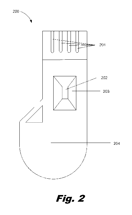
[0047] Fig. 2 is a diagram of an example of a diagnostic cassette
(200) according to the principles described herein. The diagnostic cassette
(200) may include a connector (201) or series of connectors (201) to a
computing device. The connector (201) may be a Universal Serial Bus (USB)
port, or similar technology. The connector (201) may include interface
components to allow wireless network connectivity such as IEEE 802.11 (Wi-Fi),
or a personal area network such as IEEE 802.15.1 (Bluetooth). The connector
(201) may be physically and electrically connected to the substrate (Fig. 1,
107).
[0048] The diagnostic cassette (200) may be encompassed by a
housing (204). The housing (204) may serve to protect components of the
diagnostic cassette (200), to allow for labelling of the diagnostic cassette
(200),
for identification of the diagnostic cassette (200), or similar purposes.
[0049] The housing (204) may be shaped to create a feed system
(203) to direct a fluid sample toward the fluid sample reservoir (202). The
feed
system (203) may be manufactured as a single part with the fluid sample
reservoir (202). The feed system (203) may also prevent the fluid sample from
coming into contact with other components of the diagnostic cassette (200).
[0050] Fig. 3 is a block diagram of a diagnostic cassette (300) for
micro-fluidic testing, according to an example of the principles described
herein.
The diagnostic cassette may include a fluid sample reservoir (301) to receive
fluid samples to be processed. The fluid sample reservoir may be fluidly
CA 02944193 2016-09-27
WO 2015/163921
PCT/US2014/035534
coupled to the feed system (Fig. 2, 203). The fluid sample deposited into the
fluid sample reservoir (301) may create a fluid sample flow (303) through a
channel (306) by suction created by a pump (309).
[0051] Similarly, a reagent may be stored or applied to a reagent
reservoir (302) The reagent reservoir (302) may be populated at the time of
manufacture, or may be populated closer to the time the diagnostic cassette
(300) is used. The reagent may create a reagent flow (304) through a channel
(306) by suction created by the pump (309),
[0052] The fluid sample flow (303) and reagent flow (304) may come
into contact with each other in a channel (306) to create a solution. The
solution
may then be drawn in a solution flow (305) through the channel (306). The size
and shape of the channel (306) may be constructed to affect the rate of
diffusion
in the solution flow (305). For instance, a smaller channel (306) may cause a
greater diffusion rate between the fluid sample and reagent in the solution
flow
(305). A larger channel (306) may allow a for a lower diffusion rate between
the
fluid sample and the reagent in the solution flow,
[0053] Additionally, the channel (306) may be shaped to influence the
diffusion and reaction between particles in the solution flow (305). The
channel
(306) may include microstructures (307) to restrict or impeded the solution
flow
(305) through the channel (306). The microstructures (307) may lengthen the
channel (306) allowing more time for reaction and diffusion within the
solution.
The microstructures (307) may also cause cells and particles in the solution
to
alter their path in the solution flow (305), further enhancing the diffusion
of the
fluid sample and the reagent.
[0054] The channel (306) may divide into multiple channels (306a,
306b). A diagnostic cassette (300) may have a number of sensors (308).
Multiple channels (306a, 306b) may allow for more sensors (308) to test the
solution. The sensors (308) may test for the same properties of the solution,
or
they may test different properties of the solution. The sensors may be
positioned through the channel (306) to test all or a portion of the solution.
Further, the sensors (308) may be positioned to run serially, or in parallel.
11
CA 02944193 2016-09-27
WO 2015/163921
PCT/US2014/035534
[0055] Redundant sensors (308) may be positioned on a device to
allow for the failure of an individual sensor while still allowing the
diagnostic
cassette (300) to correctly measure properties of the fluid sample. Redundant
sensors (308) may also be used to compare measurements, to ameliorate minor
variations in measurements. By averaging data obtained from multiple sensors
(308) a more accurate measurement may be provided.
[0056] A sensor (308) may be connected directly to a computer port
(Fig, 2, 201) by circuitry or by a similar method to communicate the between
the
sensor (308) and a computing device. The sensor (308) may be activated by
the computing device. The sensor (308) may also provide communication to the
computing device as to the measurement the sensor (308) has observed,
[0057] A sensor (308) may be used in combination with other
components to sort cells in the solution. The sensor (308) may be used to
control mechanical apparatus for sorting of material or cells in the solution.
The
sensor (308) may be used to control components to move or prevent movement
of material or cells in the solution.
[0058] A pump (309) may be used within the diagnostic cassette (300)
to facilitate the flow of fluids, such as the fluid sample flow (303), the
reagent
flow (304), the solution flow (305), or a combination thereof. One example of
a
pump (309) is a device known as a thermal inkjet technology. The pump (309)
may create suction by removing fluid from the channel (306). A pump (309)
may also be placed at other points in the diagnostic cassette (300) in order
to
create pressure to move the fluid. For example, a pump (309) creating pressure
may be placed in the fluid sample reservoir (301) and/or the reagent reservoir
(302). A pump (309) may mechanically move the solution.
[0059] Fig, 4 is an example of a sensor diagram (400) illustrating a
sensor (404) with a cell (402) passing a sensor (Fig,l, 105) having a sensing
electrode (404). Alternative examples of a sensor (Fig. 1, 105) may be used in
the diagnostic cassette (Fig. 1, 100). The sensing electrode (404) may detect
electrical fields (401) between the sensing electrode (404) and a grounded
electrode (403). The sensing electrode (404) may detect variations in the
electrical fields (401) to detect attributes of a cell (402) as it passes
through the
12
CA 02944193 2016-09-27
WO 2015/163921
PCT/US2014/035534
electrical fields (401). The electrical fields (401) may bend or alter based
on
properties of the cell (402). A varied electrical field (401a) may be detected
by
the sensing electrode (404). The alteration of the electrical field (401) may
indicate particular attributes of the cell (402).
[0060] A sensor (Fig. 1, 105) may be constructed to have a single
sensing electrode (404) or may be constructed to have multiple sensing
electrodes (404). Similarly, a sensor (Fig 1, 104) may be constructed to have
a
single grounded electrode (403) or multiple grounded electrodes (403).
[0061] The sensing electrode (404) may have an electrical charge
which creates an electric field (401) between the sensing electrode (404) and
the grounded electrode (403). The electric field (401) may exhibit a steady
state, allowing the sensing electrode (404) to detect variations in the
electric
field (401). For instance, the sensing electrode may detect impedance as a
cell
(402) passes through the electric field (401), bending the electric field
(401a)
and causing a variation in the impedance. The sensing electrode (404) may
then communicate the variation of impedance to other components of the
diagnostic cassette.
[0062] The electrical field (401) may be direct, or may vary in any
number of directions. Electrical fields (401) may vary in direction, shape, or
density. The electrical field (401) may be used to detect impedance, or the
resistance of the solution as it passes the sensor (Fig. 1, 105). The
localized
electric field (401) may be generated by micro-fabricated electrodes (403,
404).
[0063] Fig, 5 represents a graph (500) of a measurement of
impedance (501) over time (502) by a sensor (Fig 1, 105) The vertical axis
(501) represents increasing impedance on a linear scale. The horizontal axis
(502) represents time on a linear scale. A point further in the positive
direction
of the vertical axis (501) from the horizontal axis (502) represents a
measurement of greater impedance. A point further along the horizontal axis
(502) that is further away from the vertical axis (501) represents a
measurement
that is later in time,
[0064] The measurement of impedance starts at an initial
measurement (503), indicating a relatively low amount of impedance. As a cell
13
CA 02944193 2016-09-27
WO 2015/163921
PCT/US2014/035534
(Fig. 4, 402) passes through the electrical field (Fig. 4, 401) it may create
a
varied electrical field (Fig. 4, 401a), The varied electrical field (Fig. 4,
401a)
may be detected by an increase in the impedance measurement to a relatively
high impedance (504) (i.e., relative impedance high) with respect to the
initial
measurement (503).
[0065] The impedance measurement may drop to a relatively low
impedance (505) (i.e., relative impedance low) with respect to the initial
measurement (503) due to a number of factors. The relatively low impedance
(505) may be caused by a variation in the shape of the cell (Fig 4, 402), by
where within the electrical field (Fig. 4, 401) the cell (Fig. 4, 402) is, by
variations
in the solution flow (Fig. 3, 305), by different types of cells passing the
sensor
(Fig. 1, 105), by multiple cells (Fig. 4, 402) passing the sensor (Fig. 1,
105) and
a single cell leaving the measurement area of the sensor (Fig. 1, 105), or
combinations thereof.
[0066] The impedance measurement may increase to an absolute
maximum impedance (506) (i.e., absolute impedance maximum). This absolute
maximum impedance (506) may be caused by a cell (Fig. 4, 402) passing a
sensor (Fig. 1. 105). The presence of the cell (Fig. 4, 402) may then be
processed by the sensor or by the computer device connected by the computer
port (Fig. 1, 106). After the cell (Fig. 4, 402) passes the sensor (Fig. 1,
105), the
level of impedance measured by the sensing electrode (Fig. 4, 404) may return
to a relatively steady state level (507).
[0067] While a cell (Fig. 4, 402) may create an absolute maximum
impedance (506), a different cell (Fig. 4, 402) may decrease the impedance
measured, and create an absolute maximum impedance (506) Another
example of a sensor (Fig. 1, 105) may measure the absolute minimum
impedance (i.e., absolute impedance minimum) rather than the absolute
maximum impedance (506).
[0068] Fig. 6 represents an example of a sensor (600) used to
measure impedance on a diagnostic cassette (Fig. 1, 100). The sensor (600)
may include a pump (609) to create suction to draw the solution flow (605)
across a sensing electrode (604) and grounded electrodes (603). As the
14
CA 02944193 2016-09-27
WO 2015/163921
PCT/US2014/035534
solution flow (605) passes the sensing electrode (604) it may create
variations
in the electrical field (Fig. 4, 401) that may be detected.
[0069] The pump (600) may be a device such as, for example, a
thermal inkjet pump which creates a vacuum drawing the solution past the
sensing electrode (604) and grounded electrodes (603). The movement of cells
(Fig. 4, 402) in the solution being drawn past the sensing electrode (604) may
create a varied electric field (Fig, 4. 401a). By measuring the variation in
the
varied electric field (Fig, 4, 401a), properties of the cell (Fig. 4, 402) are
be
calculated by the sensor (Fig. 1, 105). Sensors may be placed at various
points
along the channel (Fig 3, 306) to measure attributes of cells (Fig 4, 402) in
the
solution.
[0070] Fig. 7 represents a method (700) for measuring microfluidic
samples. The method may include receiving (block 701), in a reservoir, a fluid
sample to be measured. The method (700) may include combining (block 702)
the fluid sample with a reagent to create a solution. The method (700) may
include moving (block 703) the solution through a channel. As the solution
moves (block 703) through the channel, it is measured (block 704) using a
number of sensors.
[0071] Receiving (block 701), in a reservoir, a fluid sample to be
measured may include placing a portion of a fluid sample directly into the
reservoir. A fluid sample may be obtained and received (block 701) into by the
device using a lance or needle to draw a small amount of fluid from a subject,
[0072] Combining (block 702) the fluid sample with a reagent to
create
a solution may occur in a device such as a diagnostic cassette (Fig. 1, 100).
The reagent may be placed in the reservoir receiving the fluid sample either
before or after the fluid sample is received. The reagent may be combined
(block 702) with the fluid sample to create a solution prior to receiving the
fluid
sample. The reagent may be combined with the fluid sample as part of a
process of moving (block 703) the fluid sample through a channel.
[0073] Moving (block 703) the solution through a channel may be
achieved by using a pump at one end of or within the channel to create suction
to draw the solution toward that end of the channel. Moving (block 703) the
CA 02944193 2016-09-27
WO 2015/163921
PCT/US2014/035534
solution may also be achieved by placing a pump at one end of or within the
channel to create pressure, moving the solution away from that end of the
channel.
[0074] The channel may be used to control the flow of the solution.
The control may allow for a restricted amount of solution to pass a sensor.
The
control may also allow for greater mixing between the fluid sample and
reagent,
creating more diffusion between the particles in the solution. The control may
also create a delay between the mixing of the fluid sample and the reagent to
allow time for reactions between the substances to occur.
[0075] As the solution is moving (block 703) through the channel, the
diagnostic cassette (100) measures (block 704) the solution, using the
sensors,
to detect attributes of the solution. The measuring (block 704) may occur with
a
single sensor, or with multiple sensors. The sensors may be placed serially,
or
may be placed in parallel. Sensors may be redundant, allowing for repeated
measurements of the same portion of the solution.
[0076] Fig, 8 represents a computing device for measuring
parameters of a fluid sample according to one example of the principles
described herein. The computing device (800) for measuring parameters of
fluid samples may be implemented in an electronic device. Examples of
electronic devices include servers, desktop computers, laptop computers,
personal digital assistants (PDAs), mobile devices, smartphones, gaming
systems, and tablets, among other electronic devices,
[0077] The computing device (800) may be utilized in any data-
processing scenario, including stand-alone hardware, mobile applications, a
computing network, or combinations thereof. Further, the computer (800) may
be used in a computing network, a public cloud network, a private cloud
network, a hybrid cloud network, other forms of networks, or combinations
thereof. In one example, the methods provided by the computing device (800)
are provided as a service over a network by, for example, a third party. In
this
example, the service may comprise, for example, the following: a Software as a
Service (SaaS) hosting a number of applications; a Platform as a Service
(PaaS) hosting a computing platform comprising, for example, operating
16
CA 02944193 2016-09-27
WO 2015/163921
PCT/US2014/035534
systems, hardware, and storage, among others: an Infrastructure as a Service
(laaS) hosting equipment such as, for example, servers, storage components,
network, and components, among others application program interface (API) as
a service (APlaaS), other forms of network services, or combinations thereof.
The present systems may be implemented on one or multiple hardware
platforms, in which the modules in the system can be executed on one or across
multiple platforms. Such modules can run on various forms of cloud
technologies and hybrid cloud technologies or offered as a SaaS (Software as a
service) that can be implemented on or off the cloud. In another example, the
methods provided by the computing device (800) are executed by a local
administrator.
[0078] To achieve its desired functionality, the computing device
(800)
comprises various hardware components. Among these hardware components
may be a number of processors (801), a number of data storage devices (802),
a number of peripheral device adapters (804), and a number of network
adapters (803). These hardware components may be interconnected through
the use of a number of busses and/or network connections. In one example,
the processor (801), data storage device (802), peripheral device adapters
(804), and a network adapter (803) may be communicatively coupled via a bus
(805).
[0079] The processor (801) may include the hardware architecture to
retrieve executable code from the data storage device (802) and execute the
executable code. The executable code may, when executed by the processor
(801), cause the processor (801) to implement at least the functionality of
processing data obtained from the diagnostic cassette (814), according to the
methods of the present specification described herein. In the course of
executing code, the processor (801) may receive input from, and provide output
to, a number of the remaining hardware units.
[0080] The data storage device (802) may store data, such as
executable program code, that is executed by the processor (801) or other
processing device, As will be discussed, the data storage device (802) may
specifically store computer code representing a number of applications that
the
17
CA 02944193 2016-09-27
WO 2015/163921
PCT/US2014/035534
processor (801) executes to implement at least the functionality described
herein.
[0081] The data storage device (802) may include various types of
memory modules; including volatile and nonvolatile memory. For example, the
data storage device (802) of the present example includes Random Access
Memory (RAM) (806), Read Only Memory (ROM) (807), and Hard Disk Drive
(HDD) memory (808). Many other types of memory may also be utilized, and
the present specification contemplates the use of many varying type(s) of
memory in the data storage device (802) as may suit a particular application
of
the principles described herein. In certain examples, different types of
memory
in the data storage device (802) may be used for different data storage needs.
For example, in certain examples the processor (801) may boot from Read Only
Memory (ROM) (807), maintain nonvolatile storage in the Hard Disk Drive
(HDD) memory (808), and execute program code stored in Random Access
Memory (RAM) (806).
[0082] Generally, the data storage device (802) may comprise a
computer readable medium, a computer readable storage medium, or a non-
transitory computer readable medium, among others. For example, the data
storage device (802) may be, but is not limited to, an electronic, magnetic,
optical, electromagnetic, infrared, or semiconductor system, apparatus, or
device, or any suitable combination of the foregoing. More specific examples
of
the computer readable storage medium may include, for example, the following:
an electrical connection having a number of wires, a portable computer
diskette,
a hard disk, a random access memory (RAM), a read-only memory (ROM), an
erasable programmable read-only memory (EPROM or Flash memory), a
portable compact disc read-only memory (CD-ROM), an optical storage device,
a magnetic storage device, or any suitable combination of the foregoing. In
the
context of this document, a computer readable storage medium may be any
tangible medium that can contain, or store computer usable program code for
use by or in connection with an instruction execution system, apparatus, or
device. In another example, a computer readable storage medium may be any
18
CA 02944193 2016-09-27
WO 2015/163921
PCT/US2014/035534
non-transitory medium that can contain, or store a program for use by or in
connection with an instruction execution system, apparatus, or device.
[0083] The hardware adapters (803, 804) in the computing device
(800) enable the processor (801) to interface with various other hardware
elements, external and internal to the computing device (800) For example, the
peripheral device adapters (804) may provide an interface to input/output
devices, such as, for example, a display device (809), a mouse, a keyboard or
the diagnostic cassette (814). The peripheral device adapters (803) may also
provide access to other external devices, such as an external storage device,
a
number of network devices such as, for example, servers, switches, and
routers, client devices, other types of computing devices, and combinations
thereof.
[0084] The display device (809) may be provided to allow a user of
the computing device (800) to interact with and implement the functionality of
the computing device (800). The peripheral device adapters (804) may also
create an interface between the processor (801) and the display device (809),
a
printer, or other media output devices. The network adapter (803) may provide
an interface to other computing devices within, for example, a network,
thereby
enabling the transmission of data between the computing device (800) and
other devices located within the network.
[0085] The computing device (800) may, when executed by the
processor (801), display the number of graphical user interfaces (GUIs) on the
display device (809) associated with the executable program code, representing
the number of applications stored on the data storage device (802). The GUIs
may include aspects of the executable code, including measurements taken of
properties of a fluid sample, The GUIs may display, for example, a count of a
particular type of cell carrying a particular attribute. Additionally, via
making a
number of interactive gestures on the GUIs of the display device (809), a user
may display additional information regarding properties of other particles in
the
fluid sample. Examples of display devices (809) include a computer screen, a
laptop screen, a mobile device screen, a personal digital assistant (FDA)
screen, and a tablet screen, among other display devices (809). Examples of
19
CA 02944193 2016-09-27
WO 2015/163921
PCT/US2014/035534
the GUIs displayed on the display device (809) will be described in more
detail
below.
[0086] The computing device (800) further comprises a number of
modules used in the implementation of measuring properties of a fluid sample.
The various modules within the computing device (800) comprise executable
program code that may be executed separately. In this example, the various
modules may be stored as separate computer program products. In another
example, the various modules within the computing device (800) may be
combined within a number of computer program products: each computer
program product comprising a number of the modules.
[0087] The computing device (800) may include a pumping module
(810) to, when executed by the processor (801), allow a fluid sample to be
circulated through channels on a diagnostic device. The pumping module (810)
causes a solution of a fluid sample and a reagent to pass through channels on
the diagnostic cassette (814). By controlling the amount of pressure created
by
the pumping, a time can be established to allow for diffusion and reaction
between a fluid sample and a reagent,
[0088] The computing device (800) may include a diffusing module
(811) which, when executed by the processor (801), diffuses a reagent and a
fluid sample. Diffusion may occur by controlling a pump to create movement of
particles in the solution of the fluid sample and the reagent. The diffusion
may
further be facilitated by physical characteristics of the channels through
which
the solution is passing.
[0089] The computing device (800) may include a measurement
module (812) which, when executed by the processor (801), measures
properties of particles in the solution of the fluid sample and the reagent.
The
measurement may involve a single sensor or multiple sensors. The sensors
may measure a single attribute or multiple attributes of the solution.
[0090] Based on measurements within the measurement module
(812), the calculation module (813) may perform calculations on the data and
present the data to a user through a display device (809). The calculation may
involve processes such as adding the measurement of a number of sensors,
CA 02944193 2016-09-27
WO 2015/163921
PCT/US2014/035534
comparing the measurement of a number of sensors, averaging the
measurement of a number of sensors, or any of a number of numerical analyses
may be taken to present a number to a user that may be understood and acted
upon.
[00911 Aspects of the present system and method are described
herein with reference to flowchart illustrations and/or block diagrams of
methods, apparatus (systems) and computer program products according to
examples of the principles described herein. Each block of the flowchart
illustrations and block diagrams, and combinations of blocks in the flowchart
illustrations and block diagrams, may be implemented by computer usable
program code. The computer usable program code may be provided to a
processor of a general purpose computer, special purpose computer, or other
programmable data processing apparatus to produce a machine, such that the
computer usable program code, when executed via, for example, the processor
(801) of the computing device (800) or other programmable data processing
apparatus, implement the functions or acts specified in the flowchart and/or
block diagram block or blocks. In one example, the computer usable program
code may be embodied within a computer readable storage medium: the
computer readable storage medium being part of the computer program
product. In one example, the computer readable storage medium is a non-
transitory computer readable medium.
[0092] The preceding description has been presented to illustrate and
describe examples of the principles described. This description is not
intended
to be exhaustive or to limit these principles to any precise form disclosed.
Many
modifications and variations are possible in light of the above teaching.
21