Note: Descriptions are shown in the official language in which they were submitted.
ATTENUATION CORRECTION FOR DISTRIBUTED TEMPERATURE SENSORS
USING ANTISTOKES TO RAYLEIGH RATIO
BACKGROUND
[0001/0002] Distributed temperature sensors (DTS) are optoelectronic devices
that measure temperature using optical fibers. When light is transmitted in an
optical
fiber, the photons may be elastically scattered (Rayleigh scattering) and
inelastically
scattered (Raman scattering and Brilloin scattering). In Raman scattering, the
scattered
photon may have less energy than the incident photon (Stokes Raman scattering)
due to
absorption of energy by the optical fiber or the scattered photon may have
more energy
than the incident photon (anti-Stokes Raman scattering) due to loss of energy
by the
optical fiber. A ratio of the anti-Stokes Raman scattering to the Stokes Raman
scattering may be used to determine the temperature. Alternatively, a ratio of
Stokes
Raman scattering or anti-Stokes Raman scattering to Rayleigh scattering may be
used
to determine temperature.
SUMMARY
[0003] According to an aspect of the invention, a distributed temperature
sensor, comprises an optical fiber disposed in an area where temperature is to
be
measured; a primary light source configured to inject light into the optical
fiber; a
secondary light source configured to inject light into the optical fiber, the
light injected
by the secondary light source as pulses always having a wavelength either
equal to a
Stokes Raman scatter resulting from injection of the light injected by the
primary light
source or a wavelength equal to an anti-Stokes Raman scatter resulting from
injection
of the light injected by the primary light source; a photodetector configured
to detect
backscatter light energy from the optical fiber, the backscatter light energy
including
the Stokes Raman scatter or the anti-Stokes Raman scatter resulting from the
injection
of the light injected by the primary light source, primary Rayleigh scatter
resulting from
the primary light source, and secondary Rayleigh scatter resulting from the
secondary
light source; and a processor configured to determine temperature based on a
ratio of
the Stokes Raman scatter or the anti-Stokes Raman scatter and a combination of
the
primary Rayleigh scatter and the secondary Rayleigh scatter.
[0004] According to another aspect of the invention, a method of determining
temperature comprises disposing an optical fiber in an area where the
temperature is to
1
CA 2944352 2017-12-20
be measured; injecting, using a primary light source, primary light into the
optical fiber;
injecting, using a secondary light source, secondary light as pulses into the
optical fiber,
the secondary light always having a wavelength either equal to Stokes Raman
scatter
generated by the injecting the primary light or equal to anti-Stokes Raman
scatter
generated by the injecting the primary light; detecting, using a
photodetector,
backscatter light energy resulting in the optical fiber from the primary light
source and
the secondary light source, the backscatter light energy including the anti-
Stokes
Raman scatter and or the Stokes Raman scatter generated by the injecting the
primary
light, primary Rayleigh scatter resulting from the injecting the primary
light, and
secondary Rayleigh scatter resulting from the injecting the secondary light;
and
processing the backscatter light energy to deteimine the temperature based on
a ratio of
the anti-Stokes Raman scatter and a combination of the primary Rayleigh
scatter and
the secondary Rayleigh scatter.
[0005] According to yet another aspect of the invention, a processing system
configured to compute temperature comprises an input interface configured to
receive
backscatter light energy resulting in an optical fiber based on a primary
light source and
a secondary light source injecting light into the optical fiber, the secondary
light source
injecting light as pulses always with a wavelength either equal to Stokes
Raman scatter
resulting from injecting light from the primary light source or equal to anti-
Stokes
Raman scatter resulting from injecting the light from the primary light
source, the
backscatter light energy including the Stokes Raman scatter or the anti-Stokes
Raman
scatter resulting from injecting the light from the primary light source,
primary
Rayleigh scatter based on the primary light source, and secondary Rayleigh
scatter
based on the secondary light source; and a processor configured to determine
the
temperature based on a ratio of the Stokes Raman scatter or the anti-Stokes
Raman
scatter and a combination of the primary Rayleigh scatter and the secondary
Rayleigh
scatter.
2
CA 2944352 2017-12-20
BRIEF DESCRIPTION OF THE DRAWINGS
[0006] Referring now to the drawings wherein like elements are numbered
alike in the several Figures:
[0007] FIG. 1 is a cross-sectional illustration of a borehole and a
distributed
temperatures sensor (DTS) according to embodiments of thc invention;
[0008] FIG. 2 details the DTS shown in FIG. 1 according to one embodiment
of the invention; and
[0009] FIG. 3 is a process flow of a method of measuring temperature with a
DTS according to embodiments of the invention.
DETAILED DESCRIPTION
[0010] As noted above, a distributed temperature sensor (DTS) may use a ratio
of the anti-Stokes Raman scattering to the Rayleigh scattering to determine
temperature. The DTS is susceptible to inaccuracy and drift caused by
dynamically
varying attenuation. The attenuation variance may be commonly caused by
mechanical
stress and strain or degradation of the optical fiber due to various
chemicals. For
example, when the DTS is employed in a downhole application, hydrogen ingress
into
oil and gas wells may cause degradation of the
2a
CA 2944352 2017-12-20
CA 02944352 2016-09-28
WO 2015/164004 PCT/US2015/021472
optical fiber. A looped fiber configuration and a more robust fiber glass
chemistry are among
the techniques attempted to correct the attenuation variance. Multiple lasers
with
wavelengths selected to cancel out the effects of changing attenuation have
also been used.
Embodiments of the systems and methods described herein relate to using Stokes
Raman
scattering or anti-Stokes Raman and Rayleigh scattering collected from one
laser source and
Rayleigh scattering collected from an additional laser source to determine
temperature.
According to the embodiments detailed below, inaccuracy in temperature
measurements
resulting from attenuation is eliminated.
[0011] FIG. 1 is a cross-sectional illustration of a borehole 1 and a
distributed
temperatures sensor (DTS) 100 according to embodiments of the invention. The
arrangement
shown in FIG. 1 is one exemplary use of the DTS 100. While the DTS 100 may be
used in
other environments and in other sub-surface arrangements, the exemplary DTS
100 shown in
FIG. 1 is arranged to measure temperature in a borehole 1 penetrating the
earth 3 including a
formation 4. A set of tools 10 may be lowered into the borehole 1 by a string
2. In
embodiments of the invention, the string 2 may be a casing string, production
string, an
armored wireline, a slickline, coiled tubing, or a work string. In measure-
while-drilling
(MWD) embodiments, the string 2 may be a drill string, and a drill would be
included below
the tools 10. Information from the sensors and measurement devices included in
the set of
tools 10 may be sent to the surface for processing by the surface processing
system 130 via a
fiber link or telemetry. The surface processing system 130 (e.g., computing
device) includes
one or more processors and one or more memory devices in addition to an input
interface and
an output device. The DTS 100 includes an optical fiber 110 (the device under
test, DUT).
The DTS 100 may be used to monitor temperature in the borehole 1. In other
embodiments,
with a cased borehole 1 or with the DTS 100 arranged with the optical fiber
110 along a
pipeline, the DTS 100 may be used to monitor temperature along the pipeline,
which may be
disposed on the surface or in a sub-sea environment. Embodiments of the
optical fiber 110
are further detailed below. The DTS 100 also includes a surface interrogation
unit 120,
further discussed with reference to FIG. 2.
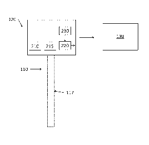
[0012] FIG. 2 details the DTS 100 shown in FIG. 1 according to one embodiment
of
the invention. The DTS 100 includes a surface interrogation unit 120, a
primary light source
210, a secondary light source 215, and one or more photo detectors 220 to
receive the
reflected signals or scatter from the optical fiber 110. The surface
interrogation unit 120 may
additionally include a processing system 230 with one or more processors and
memory
devices to process the scatter resulting from illuminating the optical fiber
110 with a fiber
3
CA 02944352 2016-09-28
WO 2015/164004 PCT/US2015/021472
core 117. Alternately, the photodetectors 220 may output the reflection
information to the
surface processing system 130 for processing. While the DTS 100 is discussed
specifically
as a temperature detector, the DTS 100 and the arrangement of the optical
fiber 110 and
surface interrogation unit 120 may be used additionally to determine other
parameters based
on the reflections or backscatter detected by the one or more photodetectors
220. In one
embodiment involving optical time domain reflectometry (OTDR), the primary
light source
210 and the secondary light source 215 may be coherent light sources in which
light waves
are in phase with one another. The primary light source 210 and the secondary
light source
215 may be a laser, for example. In an exemplary embodiment, the wavelength
and
amplitude of pulses emitted by the primary light source 210 and pulses emitted
by the
secondary light source 215 are not varied over time. The wavelength at which
the secondary
light source 215 operates is (appreciably) equal to the Stokes Raman
scattering wavelength or
the anti-Stokes Raman scattering wavelength generated by the primary light
source 210,
based on whether Stokes Raman scatter or anti-Stokes Raman scatter is used to
determine
temperature, as detailed below. The one or more photodetectors 220 obtain
three signals used
in the determination of temperature: the Stokes Raman scatter or anti-Stokes
Raman scatter
intensity or signal generated by the primary light source 210, the Rayleigh
signal generated
by the primary light source 210, and the Rayleigh signal generated by the
secondary light
source 215. The temperature determination is detailed below with reference to
Figure 3. In
alternate embodiments, optical frequency domain reflectormetry (OFDR) or pulse
code
modulation may be used. While these alternate embodiments affect the type of
interrogation
signal that is transmitted along the optical fiber 110, the return signals may
be processed to
obtain the three signals needed to determine temperature such that the
temperature
determination is unchanged from the description below.
[0013] FIG. 3 is a process flow of a method of measuring temperature with a
DTS
100 according to embodiments of the invention. At block 310, arranging the
optical fiber 110
in the area where temperature is to be determined may include arranging the
optical fiber 110
downhole as shown in FIG. 1, for example. The optical fiber 110 may also be
arranged along
a pipeline (either downhole, under the sea, or above the surface) or in a
different
environment. At block 320, the process includes disposing the primary light
source 210, the
secondary light source 215, the one or more photodetectors 220, and a
processor 230 (or
another processor, such as the surface processing system 130) to measure the
temperature. At
block 330, injecting light into the optical fiber 110 includes injecting light
from both the
primary light source 210 and the secondary light source 215. The process at
block 330 also
4
CA 02944352 2016-09-28
WO 2015/164004
PCT/US2015/021472
includes the one or more photodetectors 220 recording light intensity
resulting from Stokes
Raman scatter or anti-Stokes Raman scatter and Rayleigh scatter generated by
the primary
light source 210 and light intensity resulting from Rayleigh scatter generated
by the
secondary light source 215 and the processor 230 (130) processing the recorded
data. As
noted above, the secondary light source 215 emits light at a wavelength
corresponding to the
Stokes Raman scatter resulting from the primary light source 210 or
corresponding to the
anti-Stokes scatter resulting from the primary light source 210 based on
whether the Stokes
Raman scatter or the anti-Stokes Raman scatter is recorded by the one or more
photodetectors
220 and used in the determination of temperature. As also noted above,
alternate
embodiments may involve OFDR or pulse code modulation to interrogate the
optical fiber
110 rather than OTDR. Determining temperature at block 340 is done by the
processor 230
as detailed below.
[0014] The anti-Stokes Raman signal (light intensity resulting from anti-
Stokes
scatter generated by the primary light source 210) AS is approximated as:
¨14 F (T) = a(il )0( (A, as)
[EQ. 1]
F(T) includes all the temperature-dependent terms, a(A) is the attenuation for
the pulse
traveling down the optical fiber 110 (away from the photodetector 220), and
ot(kas) is the
attenuation for the backscatter traveling up the optical fiber 110 (toward the
photodetector
220) after undergoing the (anti-Stokes) Raman scattering effect. X55 is the
wavelength of the
anti-Stokes Raman scatter. The Stokes Raman scatter signal (light intensity
resulting from
Stokes scatter generated by the primary light source 210) S is approximated
as:
[1+ F(T)]a(2 )a(As)
4
A, s [EQ. 2]
ks is the wavelength of the Stokes Raman scatter, and a(X8) is the attenuation
for the
backscatter traveling up the optical fiber 110 (toward the photodetector 220)
after undergoing
the (Stokes) Raman scattering effect. The Rayleigh signal (light intensity
resulting from
Rayleigh scattering generated by the primary light source 210) RAp is given
by:
1
¨14 = a(A. )a(41, )
P P [EQ. 3]
P
CA 02944352 2016-09-28
WO 2015/164004 PCT/US2015/021472
o represents all the geometrical and fundamental constants associated with
RAp. In the case
of (elastic) Rayleigh scattering, there is no change in wavelength between the
pulse
(associated with the injected light) travelling down the optical fiber 110 and
the backscatter
(associated with the Rayleigh scattering) travelling up the optical fiber 110.
Thus, a(X,p) is
used twice in EQ. 2. The Rayleigh signal (light intensity resulting from
Rayleigh scattering
generated by the secondary light source 210) RAas is given by:
¨14 K = a (as )a (2õ) [EQ. 4]
"as
K represents all the geometrical and fundamental constants associated with
RAas. As noted
with reference to RAp, there is no change in wavelength between the pulse
(associated with
the injected light) travelling down the optical fiber 110 and the backscatter
(associated with
the Rayleigh scattering) travelling up the optical fiber 110. Thus, ct(kas) is
used twice in EQ.
4. As noted above, in the OTDR example being detailed for explanatory
purposes, the
secondary light source 215 transmits at a wavelength of the anti-Stokes Raman
scatter
resulting from the primary light source 210 when anti-Stokes Raman scatter
(rather than
Stokes Raman scatter) is used to determine temperature. Thus, in EQ. 4, the
designation "as"
(anti-Stokes) is used for the wavelength associated with the secondary light
source 215.
Typically, the ratio of anti-Stokes Raman scattering based on the primary
light source 210
(given by EQ. 1) to Rayleigh scattering resulting from the primary light
source 210 (given by
EQ. 3) would be used determine temperature according to the temperature
dependent terms
F(T) in EQ. 1. According to embodiments of the invention, temperature is
instead
determined according to either:
AS
as [EQ. 5]
or according to:
j RAp RAs [EQ. 6]
In EQ. 6, RAs indicates that the secondary light source 215 that results in
the Rayleigh scatter
(RAs) operates at a wavelength of the Stokes Raman scatter resulting from the
primary light
6
CA 02944352 2016-09-28
WO 2015/164004 PCT/US2015/021472
source 210. According to EQ. 1 (using anti-Stokes Raman scatter) and EQ. 5,
the equation
used to calculate temperature is given by:
4 __________ F(T)
/las
\ 4
1 [EQ. 7]
= MC
pas)
As indicated by EQ. 7, the attenuation terms in EQs. 1, 3, and 4 cancel out
such that
temperature may be calculated without the inaccuracy that results from the
attenuation terms.
The attenuation terms cancel out when EQ. 6 (rather than EQ. 5) is used to
determine
temperature. By using EQs. 5 or 6 on the backscatter originating from multiple
points along
the optical fiber 110, a temperature profile along the optical fiber 110 may
be developed.
[0015] While one or more embodiments have been shown and described,
modifications and substitutions may be made thereto without departing from the
spirit and
scope of the invention. Accordingly, it is to be understood that the present
invention has been
described by way of illustrations and not limitation.
7