Note: Descriptions are shown in the official language in which they were submitted.
CA 02944992 2016-10-05
WO 2015/163813 PCT/SE2015/050455
1
CHUCK FOR A DRILL HEAD OF A ROTATION DRILLING RIG
FIELD OF THE INVENTION
The invention relates to a chuck for a rotation drilling
drill head, wherein jaws are distributed around a grip
position axis, and wherein the chuck includes urging means
being arranged for influencing the jaws into a release
position.
The invention also concerns a drill head, a rig and a jaw
spring.
BACKGROUND OF THE INVENTION
Drill heads for exploration drilling rigs are previously
known that are equipped with hydraulically actuated chucks for
gripping, holding and rotating pipes constituting the drill
string components.
The jaws inside such chucks are radially movable between
grip and release positions with the aid of a hydraulically
powered actuator.
In order to hold the jaws in place in slots in the chuck
spindle and to move them from the grip position into the
release position, there are provided urging means effecting
the jaw movement away from the grip position axis so as to
open the chuck for releasing the grip on the drill string.
In particular, in the known chuck, the back sides of the
jaws are tapered and forced against a tapered surface
associated with the axially movable actuator.
There have been experienced problems with current urging
means in that they sometimes are not capable of fully bringing
the jaws from the grip position into the release position
thereby preventing a drill string from passing through the
chuck.
CA 02944992 2016-10-05
WO 2015/163813 PCT/SE2015/050455
2
AIM AND MOST IMPORTANT FEATURES OF THE INVENTION
It is an aim of the present invention to address the
above problem with the background art and to at least reduce
these problem.
This aim is obtained with respect to a chuck as described
above in that the urging means is a partially annular jaw
spring surrounding said axis and having two spring ends
adjacent to each other, that the jaws together form an inside
seat for the jaw spring, said seat being open towards the grip
position axis, that the jaw spring is arranged for fixing
engagement with any one of the jaws, and that the jaw spring
is provided with tool engagement means at each spring end for
co-operation with a spring installation tool.
Hereby the jaw spring can be formed for increased working
range with maintained spring action. This means that
sufficient spring force can be exerted so that the jaws are
moved_ over a sufficient radial distance to open the chuck not
only for releasing the grip but also for consistently allowing
passage of components of the drill string having considerably
larger diameters than the tubular drill rods, viz, core barrel
assemblies and even drill bits and reaming shells. This makes
the whole drill string handling process easier, since the
entire drill string can be assembled and disassembled above
the chuck. This is in contrast to background art drill head
where it dismantling of the drill string is complicated.
This is an advantage over the background art urging means
that will sometimes not fully push the jaws back against the
bowl therefore preventing such larger diameter components from
passing through the chuck. Making an effort to provide
stronger background art urging means would be insufficient to
solve this problem and also unfortunately impose a new problem
by making them more difficult to install.
CA 02944992 2016-15
WO 2015/163813 PCT/SE2015/050455
3
The jaw spring is now made from a single partial loop of
suitably strong spring material. "Partially annular" means
that the jaw spring describes a loop less than 360 in its
unstressed state, i.e. is formed as a ring having an opening
between the spring ends.
Typically, in its most stressed and compressed state,
being in the grip position of the chuck when the jaws are
closest to the grip position axis, the jaw spring is
compressed such as to describe a (partial) ring-shape close to
360 . It is important that the jaw spring also in the release
position, where the jaws are most distant from the grip
position axis, describes a ring-shape being sufficient to
contact and actuate all jaws of the chuck. This is guaranteed
by the jaw spring having sufficient length and being arranged
for fixing engagement with one of the jaws. The latter
prevents that a jaw ends up in the opening between the spring
ends.
The fact that the jaws together form an inside open seat
for the jaw spring allows mounting and replacement of the jaw
spring by contracting it so that it can be inserted into the
seat and be released from the seat and can be removed. Said
seat is open towards the grip position axis. Providing the jaw
spring with tool engagement means at each spring end for co-
operation with a spring installation tool having mating
corresponding engagement elements simplifies handling and
accurate positioning of the jaw spring in the seat.
It is preferred that the jaw spring has a flat cross
section since it allows a wide working range and easy
installation with an uncomplicated tool. Preferably a ratio
between an axial width of the jaw spring (seen along the grip
position axis) and a radial thickness thereof ranges between 2
and 6 and more preferably between 3 and 5. The tool engagement
means are suitably recesses and preferably through holes for
CA 02944992 2016-10-05
WO 2015/163813 PCT/SE2015/050455
4
engagement and co-operation with pins of a spring installation
tool being basically constructed as a lock ring installation
pliers. Typically the pins are placed at the ends of shanks of
such pliers.
Advantageously the jaw spring is provided with a fixing
means for fixing engagement with one jaw. The fixing means is
an element that is arranged such that it comes into fixed
engagement with the jaw in question when the spring is in its
mounted position. Typically the fixing means is in the form of
a peg being a bent end portion of the jaw spring, or can also
be an element such as a pin being fastened to the jaw spring,
for fixing or fastening engagement with a recess such as a
drilled hole formed in a part of the seat in any one of the
jaws. Suitably each jaw is formed with such a recess. If the
jaws are difficult to extract because they are flush or nearly
flush with the spindle, a threaded hole can be drilled in the
bottom of the recess in each jaw for allowing co-operation
with an extraction tool for extraction of the jaw from the
chuck spindle for example for replacement purposes.
The chuck includes 3, 4 or more jaws. Preferably the
chuck includes 5 jaws.
The invention also concerns a drill head for a rotation
rock drilling rig, including a chuck according to the above.
The invention also concerns a rig, including such a drill
head.
The invention further concerns a jaw spring for a drill
head chuck of a rotation drilling rig, wherein a plurality of
jaws are equally angularly distributed around a grip position
axis of the chuck, wherein the jaws co-operate with actuator
means for radial movements of the jaws between a grip position
and a release position, and wherein the jaw spring is arranged
for influencing the jaws into the release position. The jaw
spring is partially annular for surrounding said axis in its
81800340
mounted position and it has two spring ends adjacent to each
other. The jaw spring is also arranged for fixing engagement
with one of the jaws, and the jaw spring is provided with tool
engagement means at each spring end for co-operation with a
5 spring installation tool.
Advantageously the jaw spring has a flat cross section.
The tool engagement means are suitably through holes. The jaw
spring is advantageously provided with a fixing means for
fixing engagement with one of the jaws. The fixing means is
preferably a peg formed by a bent end portion of the jaw spring
for co-operation with a recess formed in the jaw.
According to one aspect of the present invention, there is
provided a chuck for a drill head of a rotation drilling rig,
rnmprising: a plurality of jaws equally angularly distributed
around a grip position axis for radial movement to and fro
relative the grip position axis which is co-axial with a
longitudinal axis of a drill string component to he received
within the chuck, wherein each one of the jaws has on a radial
inside a grip surface for engagement with the drill string
component and a groove in the grip surface, the angularly
adjacent groves together forming an inside seat open towards
the grip position axis; actuator means operative on the jaws
for effecting said radial movement of the jaws between a grip
position and a release position; and urging means arranged for
influencing the jaws into the release position, the urging
means being an annular, flat cross-section, radially-split jaw
spring received about said axis in the inside seat, said jaw
spring having a fixing means for securing the jaw spring to any
one of the jaws against movement relative to the relevant
jaw during said radial movement of the jaws, and having tool
engagement means at each of its two terminal spring ends for
Date Recue/Date Received 2021-08-10
81800340
5a
co-operation with a spring installation tool to enable
compression of the jaw spring into a smaller diameter for
mounting into the inside seat.
According to another aspect of the present invention,
there is provided a jaw spring when used with a drill head
chuck of a rotation drilling rig, the chuck comprising a
plurality of jaws that are equally angularly distributed around
a grip position axis of the chuck, wherein the jaws are
arranged to co-operate with actuator means for radial to and
fro movement of the jaws relative to the grip position axis and
between a grip position and a release position, and wherein the
jaw spring is seated in a groove in a radially-inward facing
grip surface of each jaw, the angularly adjacent groves of the
jaws together forming an inside seat open towards the grip
position axis, the jaw spring when received in the inside seat
exerting a radially outward directed spring force for biasing
the jaws into the release position, wherein the jaw spring is
of annular, radially-split, flat cross section configuration,
and defining two opposing terminal ends provided with
engagement means for co-operation with a spring installation
tool to enable compression of the jaw spring into a smaller
diameter for mounting into the inside seat, and wherein the jaw
spring has a fixing means for securing the jaw spring to any
one of the jaws against movement relative to the relevant jaw
during said radial movement of the jaws.
BRIEF DESCRIPTION OF DRAWINGS
The invention will now be explained in more detail by way
of an embodiment at the background of the annexed drawings;
wherein:
Date Recue/Date Received 2021-08-10
81800340
5b
Fig. 1 illustrates in a perspective view a rotation
drilling rig equipped according to the invention,
Fig. 2 shows in a perspective view a drill head according
to the invention,
Fig. 3 shows an axial section of a chuck according to the
invention for a drill head,
Figs. 4 and 5 show in separated, perspective views jaws of
the chuck in two different positions,
Fig. 6 shows in a perspective view a jaw spring for a
chuck according to the invention, and
Figs 7 and 8 show part sections of parts of the inventive
drill head.
DESCRIPTION OF EMBODIMENTS
Fig. 1 shows a rotation drilling rig 1 for exploration
drilling, the rig having a mast 2 with an elongate feed beam
supporting a drill head 4. The drill head 4 is movable up and
Date Recue/Date Received 2021-08-10
CA 02944992 2016-10-05
WO 2015/163813 PCT/SE2015/050455
6
down along the feed beam. A power unit 3 contains usual
machinery for the supply of power to the drill head 4.
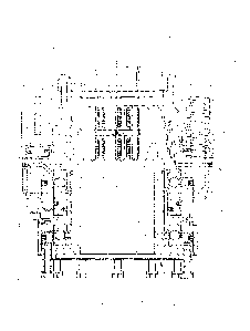
At the top of the drill head 4, shown in greater scale in
Fig. 2, there is positioned a chuck 5 for gripping the drill
string (not shown in the Figures) for transferring rotational
and axial movements to the drill string.
The chuck 5 shown in an axial section in Fig. 3 includes
a chuck spindle 17 having a plurality of radially oriented
slots 18 for radially movable jaws 7. The jaws in turn
comprise gripping surfaces for engagement with the drill
string. On top of the chuck 5, there is positioned a split
bushing 6 for guiding the drill string so as to achieve
centering of the gripped drill string axis to be essentially
co-axial with a grip position axis 9.
The jaws 7 together form a seat for a part-annular jaw
spring 8 being an urging means functioning to press the jaws 7
radially in directions from the grip position axis 9 into a
release position. Hereby the radial outsides 7' of the jaws 7
make contact with a chuck bowl 11 being part of a jaw actuator
means 10 having the function of actuating the jaws 7 between
the release position and the grip position.
The chuck bowl 11 has a tapered inside corresponding to
an inclined shape of the outside 7' of the jaws. Furthermore,
the inclined outside 7' of the jaws is stepped corresponding
to a stepped inside of the chuck bowl 11. The reason for this
design is to provide for two relative inclinations of the
contact surfaces between the jaws and the chuck bowl. This way
it is possible in a first mode, where high gripping force is
not required, to provide low gripping force and relatively
high radial displacement of the jaws outside the grip
position. In a second mode, where high gripping force is
indeed required corresponding to what is required in the grip
CA 02944992 2016-10-05
WO 2015/163813 PCT/SE2015/050455
7
position, it has been made possible to provide for such high
gripping force and relatively low radial displacement.
The jaw actuator means 10 further includes a stationary
member 14 having a hydraulic supply inlet 12 for supplying
hydraulic fluid under pressure to a piston-cylinder
arrangement. Upon actuation of the piston-cylinder arrangement
the chuck bowl 11 is pressed so as to move upwardly, (when the
chuck is oriented as seen in Fig. 3), against the force of a
number of chuck bowl return springs 13 being helical springs
that are distributed around the chuck bowl.
Upon pressurizing through the hydraulic supply inlet 12,
the chuck bowl 11 thus moves axially up (when the chuck is
oriented as seen in Fig. 3), such that the jaws 7 can move
radially out from the grip position of the chuck 5 into the
release position, where a gripped drill string component
inside the chuck 5 will be released.
Upon termination of supply of pressure fluid into the
hydraulic supply inlet 12 and connecting it to tank or the
like, the chuck bowl return springs 13 forces the chuck bowl
11 down into the closes position of the chuck, (as seen in
Fig. 3), hereby pressing the jaws 7 into the grip position
again because of the co-operation between the tapered inside
surface of the chuck bowl and the inclined outside surfaces of
the jaws.
The jaw spring 8 is arranged for firmly pressing the jaws
7 against the chuck bowl 11 thus guaranteeing the movement of
the jaws to the release position and guaranteeing passage
space for the drill string inside the chuck.
15 indicates ball bearings between the stationary member
14 and the rotatable chuck spindle 17. 16 indicates a chuck
interface for attaching it to another rotatable portion of the
drill head 4.
CA 02944992 2016-10-05
WO 2015/163813 PCT/SE2015/050455
8
Fig. 4 shows five jaws 7 separated from the other
elements of the chuck. The jaws are evenly distributed around
the grip position axis (not shown) and they are shown in Fig.
4 as they are positioned in the chuck spindle in the grip
position, the jaws 7 being closest to each other and in a
position to grip a drill string. The jaw spring does not quite
describe a full circle in this most compressed position.
24 indicates the above mentioned inside seat for the jaw
spring 8, the seat generally seen being a more or less
circular groove in the inside surface of the jaws 7 in their
mounted position. The seat 24 is open in the direction of the
grip position axis (see Fig. 3).
Fig. 5 is a representation corresponding to the one in
Fig. 4, wherein the jaws have been moved to the release
position, and wherein they have been displaced to be more
distant from each other so as to release a grip string
component. 26 indicates a fixing recess for the jaw spring.
Fig. 6 shows in a perspective view the jaw spring 8 which
is a "flat" cross section jaw spring having part annular or
part ring-shaped configuration. The flat jaw spring
construction, suitably of an ordinary spring steel material,
makes it easy to design a strong jaw spring having predictable
spring force properties over a wide working range.
At a first spring end 20 and well as at a second spring
end 21 there are provided respective tool engagement means in
the form of through holes 22 and 23 for co-operation with
engagement elements of a mounting tool for mounting the jaw
spring in the seat 24 for change or replacement of the jaw
spring or for positioning thereof during manufacture of the
chuck. The flat spring design makes a stronger jaw spring
possible. The increased spring stiffness made possible through
the inventive jaw spring fully retracts the jaws allowing
CA 02944992 2016-10-05
W02015/163813 PCT/SE2015/050455
9
passage of large diameter components though the fully open
chuck.
Even though the flat steel jaw spring is stiffer, it is
easier to install using a simple mounting tool.
The mounting tool typically functions as lock ring pliers
in that it is equipped with pins at the end of shanks that
engage in the holes 22 and 23. The tool further includes means
for bringing the pins, when they are engaged in the holes 22
and 23, together, so as to compress the jaw spring into a
smaller diameter such that it is small enough to be positioned
in the seat. The holes are preferably specially shaped in that
they are oriented so that the jaw spring will not jump off the
tool as it is compressed. Preferably the holes are parallel to
each other in the relaxed spring position.
25 indicates a fixing means being directed radially out
from said grip position axis (9 in Fig. 3). The fixing means
is as shown a bent end portion of the jaw spring 8 formed
as a peg for engagement into a corresponding hole (26 in Fig.
5) being provided in the seat 24 of (at least) one of the jaws
20 7. Any one or all jaws can have such holes for allowing the
peg to be located in the respective jaw or jaws.
As can be seen from Figs. 4 and 5, the fixing means 25 is
somewhat displaced from the centre of the jaw 7 where it is
engaged. The reason for this is that hereby better force
25 distribution is afforded between the individual jaws.
Drill bushings are required to center the drill rod in
drill heads on mineral exploration drills (also called diamond
drills). The bushings, through which the drill rod passes, are
located at the top and bottom ends of the chuck and the drill
head spindle respectively. The drill rods in exploration
drills turn at high rpm (1000 rpm is typical) and the drill
bushings help center the drill string in the drill head at the
chuck end of the spindle and also at the other end.
CA 02944992 2016-10-05
WO 2015/163813 PCT/SE2015/050455
To provide the required centering, the clearance between
the drill bushing and the drill rod has to be quite small - a
typical nominal diametrical clearance is about 1,5 mm. I.a.
the core barrel at the end of the drills string has a larger
5 diameter than that and cannot pass a typical one-piece drill
bushing. This makes it difficult to install the drill bushing
and makes dismantling of the drill string complicated.
The new feature of the split bushings described here is
that it can be made for nearly the same low cost as a one-
10 piece bushing. Also the two bushing halves remains a true
circle by locating the bushing halves against a supporting
outside diameter. The bushing halves are then bolted in place.
The split bushing is made by cutting a one piece bushing
into two equal halves. The two halves of the bushing are
located against a diameter which centralizes the bushings to
form a true circle centered on the spindle centerline
(interrupted only by the two gaps caused by the cutting
action). The two small gaps do not influence the function
since they cannot let the drill rod move significantly more
off the center line than the diametric clearance lets the
drill rod be off center.
Fig. 7 illustrates the top end of the chuck 5 with a
split bushing 6 with a gap from manufacture indicated with 28.
A locating inside seat in the chuck is indicated with 30.
Fig. 8 illustrates the bottom end of a drill head spindle
37 with a split bushing 27 with a gap from manufacture
indicated with 29. A locating inside seat in the spindle is
indicated with 31.
The bushing bores, both on top of the chuck and at the
bottom of the drill head spindle, have chamfered entry edges
on both sides. These chamfers help guide the drill rod through
the bushings whether it is moving through the bushings in
either direction. For example: when a drill rod is lowered
CA 02944992 2016-10-05
WO 2015/163813 PCT/SE2015/050455
11
though the drill head or a drill head is lowered over a drill
rod held in the foot clamp, the chamfered edges assist in
allowing smooth movement and prevents the drill rods getting
stuck at e.g. areas where there may be a small misalignment
between a drill rod and a drill head.
Split bushings are easy to install even when a drill rod
passes through the chuck. The split bushing is also easy to
remove and so allows the core barrel, reaming shell and
possibly even the drill bit which all have a larger nominal
diameter than the bushing internal diameter to be passed
through the drill head. The cost of the split bushing is
higher than a one piece bushing only by the cost of cutting
the one piece bushing in two halves. This additional cost is,
however, much less than making split bushings with no gaps.