Note: Descriptions are shown in the official language in which they were submitted.
CA 02945417 2016-10-17
TOOL LIFTING DEVICES, OILFIELD FLANGE LIFTING SAFETY DEVICES, AND
RELATED METHODS OF USE
TECHNICAL FIELD
[0001] This document discloses tool lifting devices, oilfield flange
lifting safety
devices, and related methods of use.
BACKGROUND
[0002] U.S. patent nos. 8,434,800, 8,434,801, and 8,899,645 disclose
flange lifting
devices that use freely rotatable members with lifting eyes to support one or
more flange
bolts passed through a bolt hole of the flange.
SUMMARY
[0003] A tool lifting device is disclosed comprising: arms connected to
pivot relative
to one another; and a load bearing pin supported by one or more of the arms,
the arms having
a closed position where the load bearing pin extends across a tool receiving
gap defined
between the arms.
[0004] A method is disclosed comprising: lifting a tool with a tool
lifting device that
supports the tool using a load bearing pin that extends between arms,
positioned on either
side of the tool, into an opening of the tool; and releasing the tool by
pivoting the arms of the
tool lifting device.
[0005] A tool lifting device is disclosed comprising: arms connected to
pivot relative
to one another; and a load bearing pin secured to a first arm of the arms, the
arms having a
closed position where the load bearing pin is supported by, and spans a tool
receiving gap
defined between, the arms.
[0006] A tool lifting device is disclosed comprising: arms connected to
pivot relative
to one another; a load bearing pin supported by one or more of the arms, the
arms having a
closed position where the load bearing pin extends across a tool receiving gap
defined
between the arms; and a pivot lock for restricting the arms from pivoting
relative to one
another in the closed position.
CA 02945417 2016-10-17
[0007] A method is disclosed comprising: lifting a tool with a tool
lifting device that
supports the tool using a load bearing pin spanning a pair of arms, positioned
on either side
of the tool, into an opening of the tool; pivoting a second arm of the arms
while the load
bearing pin remains in the opening in the tool; and releasing the tool by
moving the first arm
away from the tool to withdraw the load bearing pin from the opening.
[0008] A method is disclosed comprising: engaging a tool within a gap
between arms
of a tool lifting device, with a load bearing pin extended from a first arm of
the arms into an
opening in the tool; engaging a pivot lock connecting the arms; lifting the
tool with the tool
lifting device; disengaging the pivot lock; and releasing the tool by pivoting
the arms of the
tool lifting device.
[0009] In various embodiments, there may be included any one or more of
the
following features: The load bearing pin is secured to a first arm of the
arms. A second arm
of the arms defines a pin receiving slot that receives the load bearing pin
when the arms are
in the closed position. The arms are scissor arms that are connected to pivot
about a pivot
axis; an axis of the load bearing pin is parallel to the pivot axis; and the
pin receiving slot
opens into a path of circumferential movement defined by the load bearing pin.
The load
bearing pin defines a partial or fully circumferential slot that receives a
part of the second
arm. A pivot lock for restricting the arms from pivoting relative to one
another in the closed
position. The arms define respective lock openings that align in the closed
position to receive
the pivot lock. The respective lock openings are offset a pivot axis of the
arms. The pivot
lock comprises a shackle. The shackle comprises a bight-defining part and a
locking pin that
is received by aligned apertures at respective ends of the bight-defining
part; and the locking
pin passes through the respective lock openings of the arms to lock the arms
in the closed
position. The arms are connected to pivot about a pivot axis; each arm has a
tool receiving
end and a hoist connecting end; and on each arm the respective lock opening is
positioned
closer to the hoist connecting end than the pivot axis is. Each arm comprises:
a stem part that
contacts or is adjacent to the stem part of the other arm, with the stem parts
connected to
define the pivot axis; an intermediate part extended laterally away from the
other arm; and a
terminal part that that defines the tool receiving end. Each arm forms a rigid
bent sheet. The
tool lifting device is connected to a hoisting device. A tool is positioned
within the tool
2
CA 02945417 2016-10-17
receiving gap, and the load bearing pin extended into an opening in the tool.
The tool is a
flange that has an array of bolt holes, and the load bearing pin extends
through one of the
bolt holes. The load bearing pin is secured to a first arm of the arms, and in
which releasing
further comprises: pivoting a second arm of the arms while the load bearing
pin remains in
the opening in the tool; and moving the first arm away from the tool to
withdraw the load
bearing pin from the opening. Prior to lifting the tool, engaging a pivot lock
to restrict
pivoting of the arms relative to one another; and prior to releasing the tool,
disengaging the
pivot lock. The tool comprises a flange, the opening is a bolt hole opening in
the flange, and
lifting further comprises: positioning the flange adjacent a flange receiver;
and securing the
flange to the flange receiver. Positioning an annular gasket between the
flange and flange
receiver. The flange is a first flange and the flange receiver has a second
flange and is
located on a valve.
[0010] These and other aspects of the device and method are set out in the
claims,
which are incorporated here by reference.
BRIEF DESCRIPTION OF THE FIGURES
[0011] Embodiments will now be described with reference to the figures, in
which
like reference characters denote like elements, by way of example, and in
which:
[0012] Fig. 1 is a front elevation view of an embodiment of a tool lifting
device in a
closed position.
[0013] Fig. 2 is a side elevation view of the tool lifting device of Fig.
1.
[0014] Fig. 3 is a perspective view of the tool lifting device of Fig. 1.
[0015] Fig. 4 is a side elevation view of the tool lifting device of Fig.
1, supporting a
tool, and illustrating the position of one of the arms in an open position
(solid lines), and the
closed position (dashed lines).
[0016] Fig. 5 is an exploded perspective view of the tool lifting device
of Fig. 1
illustrating a method of lifting a flange with a hoisting apparatus into a
position adjacent a
valve, and partially securing the flange and flange receiver using several
flange bolts.
3
CA 02945417 2016-10-17
[0017] Fig. 6 is an exploded perspective view of the tool lifting device
of Fig. 1
illustrating a method step of opening the tool lifting device to remove the
device from the
flange. The placement of a flange gasket is also shown.
[0018] Fig. 7 is a perspective view of the valve of Fig. 5 with the flange
fully secured
to the flange receiver.
[0019] Fig. 8 is a perspective view of a further embodiment of a tool
lifting device
with a removable pivot pin.
DETAILED DESCRIPTION
[0020] Immaterial modifications may be made to the embodiments described
here
without departing from what is covered by the claims.
[0021] Lifting and rigging refers to the process and equipment used in
hoisting
objects above the ground. At a job site a team of riggers may install lifting
equipment to an
object to raise the object using a hoisting device such as a crane, mast, or
block and tackle
system. Rigging refers to equipment such as wire rope, turnbuckles, clevis,
jacks used with
cranes and other lifting equipment in material handling and structure
relocation. Rigging
systems commonly include shackles, master links, slings and lifting bags in
under water
lifting. Lifting and rigging may present numerous safety hazards for the
workers involved.
[0022] Many tasks carried out in the oil and gas industry require the
rigging and
lifting of heavy equipment. One commonly hoisted type of equipment is pipe
flange. In some
cases, pipe flanges are formed pipe fittings consisting of projecting radial
collars with an
array of bolt holes to provide a means of attachment to piping components that
have a
similar fitting. Most oilfield flanges feature a pattern of bolt holes at
discrete points along a
circular path defined on the face of the flange. Bolt hole patterns of
adjacent components
align to allow the joint to be secured along with a compressible gasket to
ensure a pressure-
tight seal. The design and specification of a flange reflects the size and
pressure capacity of
the equipment to which the flange is fitted.
[0023] Often special equipment is needed to lift and install a pipe
flange, such as a
crane or sling. One known lifting procedure includes securing a lifting eye
onto the flange.
The lifting eye may serve as a lifting point for the crane hoist or other
lifting assembly. Once
4
CA 02945417 2016-10-17
the flange has been lifted, a worker may manipulate and install the flange by
securing the
flange to the pipe by inserting bolts into the bolt holes. The lifting eye
must then be removed
from the flange after installation. Pipe flanges may be found on oil
pipelines, Christmas trees
valving, and other oil and gas applications. Specialized flange lifting
devices are known to
be used in the lifting of pipe flanges, such as various devices supplied by
PROLINETM.
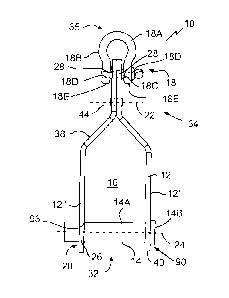
[0024] Referring to Figs. 1-3, a tool lifting device 10 is disclosed
comprising arms 12
and a load bearing pin 14. Referring to Figs. 4 and 6, arms 12 are connected
to pivot relative
to one another, for example about a pivot axis 22 between an open position
(Fig. 6) and a
closed position (Fig. 4). In some cases, load bearing pin 14 is supported by
one or both of the
arms 12. Referring to Fig. 1, while in the closed the load bearing pin 14 may
extend across,
for example span as shown, a tool receiving gap 16 defined between the arms
12. Referring
to Fig. 4, arms 12 may in use be positioned on either side of a tool 42 to be
lifted, with the
load bearing pin 14 extended from a first arm 12' of the arms 12 into an
opening / bolt hole
42A in the tool 42. In some cases the pin 14 spans the arms and is also
supported by a second
arm 12" of the arms. After the lifting operation is finished, tool 42 may be
released by
pivoting the arms 12.
[0025] Referring to Fig. 1, arms 12 may pivot relative to one another to
open or close
the tool receiving gap 16, to permit a tool to be inserted, secured, or
removed. The pivoting
of arms 12 may occur about a pivot axis 22. The pivot axis 22 may be defined
as being
aligned to the load bearing pin 14.1n some cases, the pivot axis 22 is
parallel with a
longitudinal axis 24 of the load bearing pin 14. Prongs or arms 12 may pivot
in a scissor
fashion relative to one another about axis 22. Referring to Fig. 4, a scissor
style of pivoting
action permits the arms 12 to be opened to release the tool 42 even when arm
12' is located
within a relative narrow gap 61 defined between tool 42 and an adjacent tool
such as flange
receiver 60. Referring to Figs. 1 and 5, pivot axis 22 may be defined by a
pivot pin 44. Pivot
pin 44 may be suitable device that permits up to 360 degrees of rotation about
axis 22, for
example pivot pin 44 may be a clevis pin. In other cases (not shown), arms 12
may pivot in a
non-scissor fashion, for example a jaw-like motion where tips of the jaws move
toward and
away from one another to bit a tool. Pivot axis 22 may be arranged in a
suitable orientation,
CA 02945417 2016-10-17
such as in cases where axis 22 is other than parallel to axis 24, for example
perpendicular to
the axis 24.
[0026] Referring to Figs. 1 - 3, arms 12 may have an appropriate shape to
accommodate a tool. Each of first and second arms 12' and 12" may comprise a
stem part
34, and intermediate part 38, and a terminal part 40. The stem part 34 of one
arm 12 may
contact the stem part 34 of the opposing arm 12. In some cases, stem part 34
is adjacent but
spaced from the opposing stem part 34. Stem parts 34 may be connected to
define pivot axis
22. Stem part 34 may comprise pivot pin 44 which may span between the
respective stem
parts 34 of arms 12' and 12". Each stem part 34 may define a pivot pin opening
44A, such
that openings 44A align or not to fit a straight or bent pivot pin 44. Each
arm 12 may
comprise an intermediate part 38, for example that spaces the arm 12 away from
pivot pin
44. Intermediate part 38 may extend laterally from the opposing arm 12. A
separation
between intermediate parts 38 may increase in width with increasing distance
from pivot pin
44, with each intermediate part 38 forming a shoulder. Each intermediate part
38 may
connect between a respective stem part 34 and a respective terminal part 40.
Each terminal
part 40 may mount or support the load bearing pin 14. Terminal parts 40 may
collectively
define the tool receiving gap 16. Each terminal part 40 may define a tool
receiving end 32 of
arm 12, and each stem part 34 may define a hoist connecting end 35.
[0027] Referring to Fig. 4, each of the arms 12 may take a suitable form,
such as that
of a rigid bent sheet. A sheet may have a relatively narrow thickness, thus
permitting the tool
42 to be positioned in use closely adjacent another tool, such as flange
receiver 60. In some
cases, device 10 comprises more than two arms 12 to provide additional contact
points and
support for a single pin 14 or to support multiple load-bearing pins. In some
cases one of the
arms is flat, while the other is bent as shown, and in some cases both arms
have distinct
shapes from one another.
[0028] Referring to Figs. 1 - 4 the load bearing pin 14 may be secured in
a suitable
fashion to first arm 12'. Referring to Fig. 1, the pin 14 may comprise a
smooth bore 14A and
an end flange I4B. The bore 14A passes through an opening 90 in arm 12', which
is sized to
form a stop for seating end flange 14B as shown. A further part (not shown),
such as a split
ring on the pin 14 adjacent the side of arm 12' opposite the side that the end
flange 14B
6
CA 02945417 2016-10-17
contacts, may be provided to lock the pin 14 to the first arm 12' to prevent
removal of the
pin 14 from the arm 12'. In some cases bore 14A is threaded. In some cases the
pin 14 is
secured to first arm 12' by threading to the first arm 12'.
[0029] Referring to Fig. 1, the load bearing pin 14 may extend across, for
example at
least partially or full across (shown), tool receiving gap 16. The pin 14 may
be supported by
first arm 12', or arm 12' and second arm 12". In use, load bearing pin 14
forms a surface
that bears the weight of tool 42.
[0030] Referring to Figs. 2 and 3, second arm 12" may define a pin
receiving slot 20
that receives the load bearing pin 14 when the arm 12" swings into the closed
position.
Referring to Fig. 2, the pin receiving slot 20 may open into a path 30 of
circumferential
movement defined by the load bearing pin 14. Slot 20 may form a mouth that
laterally opens
in the direction of a tangent 30A along the path 30 of circumferential
movement. Referring
to Fig. 3, slot 20 may comprise a base ledge 20A that supports the pin 14
during weight
bearing that occurs during lifting and rigging.
[0031] Referring to Figs. 1 and 3, the pin 14 may be shaped to mate with
the second
arm 12". In one case the load bearing pin 14 defines a slot, for example a
partial or fully
(shown) circumferential slot 26 that receives a part 93 of the second arm 12".
Part 93 may
form part of slot 20 of second arm 12". The slot 26 may engage with the second
arm 12"
during use to grip and restrict any pull out or push through axial forces that
act through the
pin 14 against the second arm 12". Instead of a slot 26, other suitable
structures may be used
to restrict such movement and support the pin 14, for example using a
shoulder, or a tapered
portion, for example defined by a part (not shown) of pin bore 14A that gets
wider or
narrower with increasing distance from end flange 14B.
[0032] Referring to Fig. 1, device 10 may comprise a pivot lock 18 for
restricting, for
example locking, the arms 12 against rotation. Pivot lock 18 may restrict the
arms 12 from
pivoting relative to one another when the device 10 is in the closed position.
Pivot lock 18
may lock the device by a suitable mechanism, such as by inserting a part
through respective
openings 28 defined by the arms 12. In some cases, each opening 28 is defined
by a
respective stem part 36. The lock openings 28 may be located closer to the
hoist connecting
end 35 than the pivot axis 22 is. When the device is in the closed position,
openings 28 may
7
CA 02945417 2016-10-17
be aligned and the pivot lock 18 may be insertable through openings 28. In
some cases, pivot
lock 18 comprises a pin 18C that is inserted into the aligned openings 28 to
lock the arms 12.
Prior to lifting a tool, pivot lock 18 may be engaged to restrict pivoting of
the arms relative
to one another and such may allow for safer operation of the flange during
lifting. Prior to
releasing the tool the pivot lock may be disengaged to allow the arms 12 to be
swung into the
open position and the device 10 to be removed from the tool.
[0033] Referring to Fig. 1, the pivot lock 18 may comprise a lifting
shackle 18A. The
shackle 18A may permit the device 10 to be locked while simultaneously
providing a
mechanism for which the device 10 may be attached to a lifting device, such as
a crane. The
shackle 18A may comprise a bight defining part 18B, such as a clevis as shown,
that is
shaped to engage with a chain or hook, for example a U-shape, V-shape, D-shape
or suitable
shapes, including twisted shapes. Shackle 18A may comprise a locking pin 18C
that is
received by aligned apertures 18D at respective ends of the bight defining
part 18B. The
locking pin 18C may pass through the respective lock openings 28 of the arms
12 to lock the
arms 12 in the closed position. In use, a worker may place the bight defining
part 18B on
either side of the device 10, with the ends 18E of the part 18B flanking the
arms 12. Next,
the worker may insert and secure, for example by threading as shown, the
locking pin 18C
into engagement with ends 18E. The pin 18C may also thread to openings 28. The
locking
pin 18C may have a threaded end and smooth bore, or threaded end and bore. Any
suitable
shackle may be used, for example, an anchor, bow, twist, D-shackle, headboard,
pin, snap, or
threaded shackle. Suitable locking pins may be used, for example a twist
clevis or twist
shackle. Other types of non-shackle pivot locks may also be used, for example
fasteners such
as bolts.
[0034] Referring to Fig. 5, in use tool lifting device 10 may be connected
to a hoist in
order to lift, position, and secure a tool to another part. In the example
shown in Figs. 5-7,
the device 10 is used to position a pipe flange 42B into place on a flange
receiver 60 of an
oilfield valve 58, so that the flange 42B may be secured and sealed to the
flange receiver 60.
Two or more devices 10 may be used to balance the load of the flange 42B. The
devices 10
may be positioned at suitable locations on the flange 42B, for example with
the left device
8
CA 02945417 2016-10-17
positioned between 7 and 11 o'clock, for example between 9 and 10 o'clock, and
the right
device 10 positioned between 5 and 1 o'clock, for example between 2 and 3
o'clock.
[0035] Referring to Fig. 5, in an initial stage the flange 42B is engaged
within gaps
16 between sets of arms 12 of devices 10. Engagement may be carried out by
inserted the
pins 14 of each device 10 into respective bolt holes 42A in the flange 42B.
The arms 12 of
devices 10 may then be pivoted to close the arms 12 around the flange 42B. The
pivot locks
may be engaged, for example by connecting shackles 18A to each device 10. The
shackles
18A may then be connected to a hoisting device such as a crane, which may
suspend a
suitable tether such as a pair of lifting chains 48 or cables, each fitted
with a shackle
connector such as a hook 46. The hooks 46 may be secured to the shackles 18A,
and the
flange 42B lifted by applying tension through the chains 48 to raise the
flange 42B. The
crane may be operated to position the flange 42B into a desired position, for
example
adjacent a flange receiver 60, which has a flange that corresponds to the
flange 42B, of an
oilfield part such as a valve 58. Referring to Fig. 5, while the flange 42B is
supported by the
crane, a user may align the bolt hole patterns on the flange 42B and flange
receiver 60, and
place several bolts 52, for example at positions near a base of the flange
42B. Nuts 50 may
be connected to secure the bolts 52 in place, for a loose connection at this
point.
[0036] Once the flange 42B is independently supported by the bolts 52, the
devices
10 may be removed. Referring to Fig. 6, the removal process may be started by
disengaging
the pivot lock, for example by removing the shackles 18A from each device 10.
Afterward,
both flanges 42B may be released by swinging the arms into an open position
where the non-
pin-mounting arm 12" is clear of the flange 42B and the pins 14 of arms 12'
remain in the
respective bolt holes 42A. The devices l 0 may be moved away from the flange
42B to
withdraw the pins 14 from the respective bolt holes 42A. An annular gasket 56
may be slid
into the gap between the flange 42B and the flange receiver 60. Referring to
Fig. 7, the
remaining bolts 52 may then be inserted between aligned bolt hole patterns of
flange 42B
and receiver 60, and nuts 50 used to tightly secure and seal the flanges
together to complete
the connection. A process to remove the flange 42B from the receiver 60 may be
achieved by
carrying out some or all of the steps in reverse.
9
CA 02945417 2016-10-17
[0037] Pins 14 may be replaced with flange bolts in some cases. Non-
shackle pivot
locks may be used, such as a cap that mounts over the hoist connecting ends 35
of arms 12,
or a band or cable that wraps around the stem parts of the arms. Lever arms
may be used to
secure the arms 12 together. Aligned openings 28 are not required to achieve a
pivot lock. In
one case one arm 12 mounts a spring-biased pin that aligns with an opening in
the other arm
to engage and create a pivot lock, which can be disengaged by applying
pressure against the
biasing force of the pin to remove the pin from the opening and permit the
arms 12 to be
pivoted out of the closed position. The flange 42B may be a blind flange. In
other cases the
flange 42B may be part of process equipment such as a valve, or piece of
piping. The load
bearing pin 14 may be retractable. In one case a pair of seven pound devices
10 were able to
lift a tool of over 1700 pounds, with each device 10 rated at 850 pounds.
Referring to Fig. 6,
a pair of left and right handed devices 10B and 10A may be used, such that
both devices can
be inserted into and removed from the same flange face, while permitting the
respective
swing arms 12" to swing in opposite directions, in this example outward, to
avoid
obstruction with interior components such as gasket 56. The devices 10 may be
made of QT
100 Steel, which is durable in cold weather applications, such as in cases
where the ambient
temperature is at or below minus forty Celsius. The devices 10 disclosed here
may be used in
any lifting applications, and in some cases pulling or pushing applications as
well, and
including oil and gas lifting, fabrication lifting, and use in association
with a picker truck.
The devices 10 may be used with tether cranes, or with devices that pull or
push via rigid
tethers. In some cases the devices 10 may be used to eliminate the use of
slings and pin bars.
The devices 10 may fit into a conventional tool carrier device, such as a tool
box. No lifting
eye may be required. Referring to Fig. 8 a further embodiment of a device 10
is illustrated
with a pivot lock formed by a bolt 44C and nut 44B combination as a pivot pin
44, and a
pivot pin 14 that fits into a circular opening in arm 12".
[0038] In the claims, the word "comprising" is used in its inclusive sense
and does
not exclude other elements being present. The indefinite articles "a" and "an"
before a claim
feature do not exclude more than one of the feature being present. Each one of
the individual
features described here may be used in one or more embodiments and is not, by
virtue only
CA 02945417 2016-10-17
of being described here, to be construed as essential to all embodiments as
defined by the
claims.
11