Note: Descriptions are shown in the official language in which they were submitted.
CA 02945473 2016-10-11
WO 2015/160267 PCT/NZ2015/000029
- 1 -
Reciprocating Engine
FIELD OF THE INVENTION
This invention relates to a reciprocating engine, and in particular, but not
exclusively to a
crankshaft-less reciprocating engine for use in vehicles and power generation.
BACKGROUND
Many vehicles and other machines use reciprocating engines. A key feature of
any engine
is its efficiency.
The use of a crankshaft limits the efficiency of many engines. When the
reciprocating
piston is near top dead centre, or near bottom dead centre, the crank of the
crankshaft is at
an angle that limits the turning force or torque that can be applied by the
piston to the
crank shaft.
Also, many engines are only efficient when operating at high speed. And since
many
applications require rotary motion at a lower speed, reduction gearing is
required. The
use of the reduction gearing causes additional power losses.
The high pressures in modern engines contribute to the production of nitrous
oxide
emissions which are harmful to the environment. The high pressures and
temperatures
produce additional stresses on the engine components, as well as increasing
the operating
noise levels.
The design of combustion chambers and the dynamics within the chambers is also
a key
factor in the overall efficiency of an engine. Many engines have poor fuel air
mixing and
combustion characteristics.
The breathing efficiency of engines is also a key factor in efficiency. Four
stroke engines
for example use an entire rotation of the crank shaft to simply purge and
recharge each
cylinder. Conventional two strokes overcome this problem but experience
difficulty in
completely purging exhaust gases from the combustion cylinders.
CA 02945473 2016-10-11
WO 2015/160267
PCT/NZ2015/000029
- 2 -
OBJECT =
It is therefore an object of the present invention to provide a reciprocating
engine which
will at least go some way towards overcoming one or more of the above
mentioned
problems, or at least provide the public with a useful choice.
STATEMENTS OF THE INVENTION
Accordingly, in a first aspect, the invention may broadly be said to consist
in a
reciprocating engine having a fixed body and at least one rotating and
reciprocating
member, the reciprocating engine also having at least one combustion chamber,
and the or
each combustion chamber is defined between at least a fixed member connected
to the
fixed body and at least one rotating and reciprocating member, and the or each
rotating
and reciprocating member is coupled to the fixed body in such a manner that
reciprocating
motion of the or each rotating and reciprocating member produces rotation of
the or each
rotating and reciprocating member, and the or each rotating and reciprocating
member is
coupled to an output shaft in such a manner that the rotational motion only of
the or each
rotating and reciprocating member is transferred to the output shaft.
Preferably the or each rotating and reciprocating member is concentric with
the output
shaft.
Preferably the or each fixed member is concentric with the or each rotating
and
reciprocating member.
Preferably the or each fixed member is in the form of a fixed piston member.
Preferably the or each rotating and reciprocating member includes at least one
outer
cylinder configured to engage with and reciprocate about a fixed member.
Preferably the or each combustion chamber is an annular shaped combustion
chamber.
Preferably the or each annular shaped combustion chamber is defined between a
fixed
member, an outer cylinder of at least one rotating and reciprocating member,
and an inner
cylinder of the rotating and reciprocating member.
=
CA 02945473 2016-10-11
WO 2015/160267 PCT/NZ2015/000029
- 3 -
Preferably the or each rotating and reciprocating member is coupled to the
fixed body via
one or more cylindrical end cams which are mated with one or more cam
engagement
rollers.
Preferably the or each cam engagement roller is supported by the fixed body of
the
reciprocating engine.
Preferably = the or each cylindrical end cam is a part of the or each rotating
and
reciprocating member.
Preferably the or each rotating and reciprocating member is coupled to the
output shaft via
a splined joint.
Preferably the or each splined joint includes a male spline profile on the
output shaft and a
female spline profile on the associated rotating and reciprocating member.
Preferably .the or each fixed member includes provisions to mount fuel
injectors and/or
fuel igniters.
Preferably the reciprocating engine also includes one or more pre-charge
chambers, and
each pre-charge chamber communicates with at least one combustion chamber.
Preferably the reciprocating engine also includes one or more pumping
chambers, and
each pumping chamber communicates with at least one pre-charge chamber.
Preferably = the or each rotating and reciprocating member includes a plunger
which
provides the pumping action within the or each pumping chamber.
Preferably the or each pumping chamber is an annular chamber situated about
the or each
fixed member.
Preferably the or each pre-charge chamber is an annular chamber situated
within the or
each fixed member.
Preferably the passage of air from the or each pumping chamber to the or each
pre-charge
chamber is controlled by a pre-charge inlet valve.
CA 02945473 2016-10-11
WO 2015/160267 PCT/NZ2015/000029
- 4 -
Preferably the or each pre-charge inlet valve is a pressure operated valve
configured to
allow air to enter the pre-charge chamber when the pressure in the pumping
chamber
exceeds the pressure within the pre-charge chamber.
Preferably airflow into the or each pumping chamber is controlled by a pumping
chamber
inlet valve.
Preferably the or each pumping chamber inlet valve is a pressure operated
valve
configured to allow air to enter the pumping chamber when the ambient pressure
surrounding the reciprocating engine exceeds the pressure within the pumping
chamber.
Preferably the transfer of air from the or each pre-charge chamber to its
associated
combustion chamber is controlled by inlet ports or passages which are only
open when its
associated outer cylinder is at or near the end of its combustion or power
stroke.
Preferably the inlet passages for each combustion chamber are a series of
longitudinal
slots situated about the circumference of the inner cylinder.
Preferably the transfer of exhaust gases out of the or each combustion chamber
is
controlled by exhaust ports or passages which are only open when its
associated outer
cylinder is at or near the end of its combustion or power stroke.
Preferably the exhaust ports for each combustion chamber are a series of holes
situated
about the circumference of its associated outer cylinder.
In a second aspect, the invention may broadly be said to consist in a vehicle
or power
generation machine incorporating at least one reciprocating engine
substantially as
specified herein.
The invention may also broadly be said to consist in the parts, elements and
features
referred to or indicated in the specification of the application, individually
or collectively,
and any or all combinations of any two or more of the parts, elements or
features, and
where specific integers are mentioned herein which have known equivalents,
such
equivalents are incorporated herein as if they were individually set forth.
CA 02945473 2016-10-11
WO 2015/160267 PCT/NZ2015/000029
- 5 -
DESCRIPTION
Further aspects of the present invention will become apparent from the
following
description which is given by way of example only and with reference to the
accompanying drawings in which:
FIGURE 1 is a perspective view of a first example of a reciprocating engine
assembly according to the present invention,
FIGURE 2 is a cross sectional perspective view of the main fixed parts of the
first
example of a reciprocating engine and the output shaft,
FIGURE 3 is a perspective view of a rotating and reciprocating member of the
first example of a reciprocating engine,
FIGURE 4 is a cross sectional perspective view of the rotating and
reciprocating
member,
FIGURE 5 is a cross sectional perspective view of the assembled reciprocating
engine,
FIGURE 6 is a second cross sectional perspective view of the assembled
reciprocating engine,
FIGURE 7 is a perspective view of a cylindrical section of a fixed member of
the
reciprocating engine,
FIGURE 8 is perspective view of the output shaft,
FIGURE 9 is an enlarged cross sectional perspective view showing transfer
ports
between a pre-charge chamber arid a combustion chamber,
FIGURE 10 is an enlarged cross sectional perspective view showing pumping
chamber inlet ports and pre-charge chamber inlet ports,
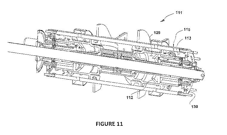
FIGURE 11 is a cross sectional perspective view of a second example of a
reciprocating engine assembly according to the present invention,
CA 02945473 2016-10-11
WO 2015/160267
PCT/NZ2015/000029
- 6 -
FIGURE 12 is a cross sectional perspective view of the main rotating and
reciprocating member of the second example of a reciprocating
engine,
FIGURE 13 is a cross sectional perspective view of the main fixed parts of the
second example of a reciprocating engine,
FIGURE 14 is a perspective view of an output shaft of the second example of a
reciprocating engine,
FIGURE 15 is a cross sectional perspective view of the second example of a
reciprocating engine in an assembled state showing ignition
components, and
FIGURE 16 is a cross sectional perspective view of the second example of a
reciprocating engine in an assembled state showing components of
the fuel system.
First Example
The main components of a first example of a reciprocating engine (11)
according to the
present invention are shown in Figures 1 to 10. The reciprocating engine (11)
is of the
type having a reciprocating sleeve which reciprocates over a fixed piston or
pistons, and is
an internal combustion engine in which the combustion chamber breaths in a
similar
manner to a two stroke engine. The engine is crankshaft-less, and
reciprocating motion is
converted into rotary motion via an end cam and cam engagement roller
arrangement.
As with other two stroke engines, the reciprocating engine (11) includes a pre-
charge
chamber (13) which supplies compressed air to each combustion chamber (15).
However,
as will be explained below, the operating sequence of the reciprocating engine
(11) is
quite different to conventional two stroke engines.
The reciprocating engine (11) is also distinguished by the feature of a fixed
body (17), a
rotating and reciprocating member (19) and an output shaft (21), that are all
concentric to,
and aligned with, a primary axis of the major components of the reciprocating
engine
(11). The fixed body (17) is fitted with engine mounts (23) to support the
engine in a
CA 02945473 2016-10-11
WO 2015/160267 PCT/NZ2015/000029
- 7 -
vehicle or a stationary situation. This arrangement provides a relative
compact and light
weight engine with a significant power to weight ratio.
In this example, the reciprocating engine (11) has two amiular shaped
combustion
chambers (15). Each combustion chamber (15) is defined between a fixed member
(25)
connected to the fixed body (17) and the rotating and reciprocating member
(19). Each
fixed member (25) is in the form of a fixed piston member.
The rotating and reciprocating member (19) includes two outer cylinders (27)
that are
configured to engage with and reciprocate about their respective fixed members
(25).
Each combustion chamber (15) is an annular shaped chamber that is defined
between its
associated fixed member (25), outer cylinder (27) and an inner cylinder (29)
of the
rotating and reciprocating member (19). An inside diameter of the inner
cylinder (29) fits
over, and reciprocates relative to, the output shaft (21).
The rotating and reciprocating member (19) is coupled to the fixed body (17)
in such a
manner that reciprocating motion of the rotating and reciprocating member (19)
produces
rotation of the rotating and reciprocating member (19). In this example, this
is achieved
by coupling the rotating and reciprocating member (19) to the fixed body (17)
via two
opposed cylindrical end cams (31) which are each mated with a cam engagement
roller
(33). The two opposed cylindrical end cams (31) are integral parts of the
rotating and
reciprocating member (19). Each cam engagement roller (33) is supported by the
fixed
body (17) of the reciprocating engine.
The cam engagement rollers (33) are connected to the fixed body (17) of the
reciprocating
engine via roller support blocks (35). Each roller support block (35) includes
two stub
axles about which the individual cam engagement rollers (33) are mounted. The
rollers
(33) include needle roller bearings to provide minimal rolling resistance
while
experiencing the thrust loads from the rotating and reciprocating member (19)
during its
respective Combustion strokes. It can be seen in Figure 6 that the rollers
(33) are tapered,
with the apex of the taper of each roller (33) coinciding with the principal
axis of the
output shaft (21).
The rotating and reciprocating member (19) is coupled to the output shaft (21)
in such a
manner that only the rotational motion of the rotating and reciprocating
member (19) is
CA 02945473 2016-10-11
WO 2015/160267
PCT/NZ2015/000029
- 8 -
transferred to the output shaft, This is achieved by coupling the rotating and
reciprocating
member (19) to the output shaft (21) via a splined joint, The splined joint
includes a male
spline profile (37) on the output shaft (21) and a female spline profile (39)
on the rotating
and reciprocating member (19).
This arrangement means that when the reciprocating engine (11) is running, and
the
rotating and reciprocating member (19) is rotating and reciprocating, only the
rotational
motion of the rotating and reciprocating member (19) is transferred to the
output shaft
(21).
With reference to Figure 2 it can be seen that the fixed body (17) consists
primarily of an
outer cylindrical sleeve (41) and an end cap (43) at each end of the
cylindrical sleeve (41).
The fixed pistons (25) are connected at their bases to the end caps (43).
The fixed pistons (25) include provisions to mount fuel nozzles (45) and/or
fuel igniters
(47). With reference to Figures 6 and 10 a fuel nozzle (45) is shown fitted
into
provisions in the crown of the fixed piston (25). The fuel nozzles (45) are
situated within
longitudinal tubes (49) which form part of a piston skirt (51) of each fixed
member or
fixed piston (25). The operation of the fuel injection system is explained
below.
It can be seen also that a shroud (53) is connected to the circumference of a
crown (55) of
each fixed piston (25), and the shroud (53) is angled or tapered toward the
principal axis
of the fixed piston (25). The shroud (53) is designed to direct any incoming
air and fuel
mixture along the outer surface of the inner cylinder (29) for efficient
scavenging of the
combustion chamber (15) at the end of each combustion stroke.
In this example, the reciprocating engine (11) includes two pre-charge
chambers (13), and
each pre-charge chamber (13) communicates with an associated combustion
chamber
(15). Each pre-charge chamber (13) is situated within the piston skirt (51) of
its
associated fixed piston (25). Each pre-charge chamber (13) is an annular
shaped chamber
defined between its associated piston skirt (51), end cap (43), piston crown
(55) and the
outer surface of the inner cylinder (29).
The reciprocating engine (11) also includes two pumping chambers (57). Each
pumping
chamber (57) draws in air from an air inlet system (59) which includes an air
filter, and
CA 02945473 2016-10-11
WO 2015/160267 PCT/NZ2015/000029
- 9..
supplies the pumped air to an associated pre-charge chamber (13). Each pumping
chamber (57) is an annular shaped chamber situated about its associated fixed
piston (25).
Each pumping chamber (57) is defined between an inside surface of the outer
cylindrical
sleeve (41), an inner surface of one of the end caps (43), and outer surface
of an
associated piston skirt (51), and a plunger (61).
A pumping action within each pumping chamber (57) is provided by the plunger
(61)
which is coupled to the rotating and reciprocating member (19) associated with
the fixed
piston (25). Each time the rotating and reciprocating member (19) moves
through a
complete cycle, the plunger (61) also moves through a complete pumping cycle
within the
pumping chamber (57).
Fresh air is initially drawn from outside the engine and into the pumping
chambers (57)
via the air inlet system (59). Airflow into the pumping chambers (57) is
controlled by an
arrangement of pumping chamber inlet valves (63), which in this case is
provided by a
series of reed valves situated on the inside face of a first air inlet
cylinder (65) situated in
the air inlet system (59).
Each pumping chamber inlet valve (63) is a pressure operated valve configured
to allow
air to enter the pumping chamber (57) when the ambient pressure surrounding
the
reciprocating engine (11) exceeds the pressure within the pumping chamber
(57).
The passage of air from each pumping chamber (57) to its associated pre-charge
chamber
(13) is controlled by a pre-charge inlet valve (67) arrangement situated about
the internal
circumference of a second air inlet cylinder (69) which is concentric to, and
inside, the
first air inlet cylinder (65). Each pre-charge inlet valve (53) is a pressure
operated valve,
for example a reed valve, configured to allow air to enter the pre-charge
chamber (13)
when the pressure in the pumping chamber (47) exceeds the pressure within the
pre-
charge chamber (13).
With reference to Figure 9 it can be seen that the transfer of air from each
of the pre-
charge chambers (13) to its associated combustion chamber (15) is controlled
by inlet
ports or passages (71). The inlet passages (71) for each combustion chamber
(15) are a
series of longitudinal slots situated about the circumference of the inner
cylinder (29).
The inlet passages (71) are situated on the inner cylinder (29) in such a
location that the
CA 02945473 2016-10-11
WO 2015/160267 PCT/NZ2015/000029
- 10 -
inlet passages (71) only provide an open pathway for air to transfer from the
pre-charge
chambers (13) to their respective combustion chambers (15) when the associated
outer
cylinder (27) is at or near the end of its combustion or power stroke.
The transfer of exhaust gases out of the combustion chambers (15) is
controlled by
exhaust ports (73). The exhaust ports (73) for each combustion chamber (15)
are a series
of holes situated about the circumference of each outer cylinder (27).
The exhaust ports (73) of each combustion chamber (15) are only open when the
associated 'outer cylinder (27) is at or near the end of its combustion or
power stroke. At
all other times the exhaust ports (73) surround the piston skirt (51) and do
not provide an
open exit for exit gases to exit the combustion chamber (15).
The exhaust ports (73) align with exhaust passages (59) within the plunger
(61). And at
the same time that the exhaust ports (73) clear the piston skirt (51) and
become open, they
also align with secondary exhaust ports (75) in the outer cylindrical sleeve
(41). An
exhaust manifold (77) surrounds the secondary exhaust ports (75) and collects
the exhaust
gases and directs them to an exhaust pipe (79).
A narrow air blast pumping chamber (81) can also be seen in Figure 10. The air
blast
pumping chamber (81) is defined between the outer circumference of the output
shaft (21)
and the inside diameter of an air blast pumping chamber skirt (83) situated
within the pre-
charge chamber (13). Air is drawn into the air blast pumping chamber (81) from
the pre-
charge chamber (13) via a pressure operated air blast inlet valve (85), During
the
compression stroke, the free end of the inner cylinder (29) acts as a piston
as it moves into
the air blast pumping chamber (81) and compresses the air within the chamber
(81).
This chamber (81) communicates with the longitudinal tubes (49) noted above.
Air
travels from the air blast pumping chamber (81) and, into the longitudinal
tubes (49) via a
pressure operated air blast outlet valve (87). The blast of air then travels
through the fuel
nozzles (45) and into the combustion chamber (15). Fuel supplied to the fuel
nozzles (45)
by a fuel management system is picked up by the blast of air from the air
blast pumping
chamber (81) and is atomised and transported to the combustion chamber (15)
via the fuel
nozzles (45).
CA 02945473 2016-10-11
WO 2015/160267 PCT/NZ2015/000029
- 11 -
With reference to Figures 4 and 5, the operating sequence of this twin
cylinder
reciprocating engine (11) is now described as follows;
= As the left hand outer cylinder (27) is moving through its power stroke
(i.e. toward
the position shown in figure 5), its associated plunger (61) is moving away
from
the pumping chamber inlet valves (63) and is drawing air from the atmosphere
into the pumping chamber (57).
= Then as the right hand cylinder (27) moves through its power stroke, the
left
plunger (61) is compressing air within the left pumping chamber (57). During
this
same stroke the air pressure within the left pumping chamber (57) will become
greater than the pressure within the left pre-charge chamber (13) and
compressed
air Will fill the left pre-charge chamber (13).
= Then, the left hand cylinder (27) will move through its power stroke
again, and
when it is at the end of its power stroke the inlet passages (71) will become
open
and the compressed air within the left pre-charge chamber (13) will enter and
purge the left combustion chamber (15) since the left cylinder exhaust ports
(73)
will also be open,
= Then the left hand cylinder (27) moves through a compression stroke
again, prior
to fuel injection, and spark ignition at the start of the next power stroke.
It could be said that each intake of air passes through a six stage process
which takes
place during five strokes of the associated cylinder;
1. air is drawn into pumping chamber during a first power stroke,
2. the same air is compressed in the pumping chamber and passes into the
pre-charge chamber during a first compression stroke,
3. the air then sits idle in the pre-charge chamber during a second power
stroke,
.4, then at the end of the second power stroke and at the beginning of a
second
compression stroke the air is transferred into the combustion chamber, and
CA 02945473 2016-10-11
WO 2015/160267
PCT/NZ2015/000029
= 12 -
as it enters the combustion chamber it displaces the exhaust gases from the
previous combustion event,
5, then the fresh charge of air is compressed within the combustion chamber
during the second compression stroke, and
6. then during a third power stroke the air that was drawn into the pumping
= chamber during the first power stroke is used in combustion and is purged
out of the combustion chamber at the end of the third power stroke.
Or alternatively, it could be said that air moving through the engine
undergoes five
distinct phases which take place during five strokes of the associated
reciprocating
cylinder;
1. Intake - air is drawn into the pumping chamber during the first stroke,
which is
part of the first Combustion event.
2. Compress - the same air is compressed in the pumping chamber and passes
into
the pre-charge chamber during the second stroke, which is part of the first
compression event.
3. Purge - air is transferred into the combustion chamber from the pre-charge
chamber thereby displacing exhaust gases out the exhaust ports, at the end of
the
third stroke, which is part of the second combustion event.
4. Prepare - air is then mixed with fuel and compressed into a combustible
mixture
in the combustion chamber during the fourth stroke, which is part of the
second
compression event.
5, Combust - a spark ignites the air/fuel mixture creating gaseous expansion
and
cylinder pressure. This forms the power source behind the fifth stroke, which
is
part of the third combustion event.
This is sometimes referred to as the 'Shepherd Two Stroke Combustion Cycle',
It is envisaged that the reciprocating engine (11) could be used in a range of
vehicles, or
in power generation equipment, or in other stationary engine applications.
CA 02945473 2016-10-11
WO 2015/160267
PCT/NZ2015/000029
- 13
Ideally the end cam profile is as close as possible to forty five degrees to
the principal axis
of the engine for as much of the profile as possible. This allows for a one to
one transfer
of force from the reciprocating cylinders into torque in the output shaft, for
as much of the
stroke of each reciprocating cylinder as possible. In this way it is envisaged
that much
greater efficiencies will be achieved that with convention crankshaft engines
which
operate at inefficient crank angles for the greater part of each crank
revolution.
Second Example
A second example of a reciprocating engine (111) according to the present
invention is
shown in Figures n to 16. The reciprocating engine (111) is similar to the
first example
of a reciprocating engine (11) except as noted in the following description.
The structure of the reciprocating engine (111) has been simplified to some
extent,
eliminating the need for multiple end bulkheads at each end of the engine as
used in the
first example. The valves which control the flow of air from a pumping chamber
(113) to
a pre-charge chamber (115), that is, the pumping chamber outlet valves (117)
and the pre-
charge outlet valves (119), are now situated within the base of the fixed
piston (121).
As in the first example, the pumping chamber outlet valves (117) and the pre-
charge
outlet valves (119) control the movement of compressed air into and out of the
pre-charge
chamber (115) which is made up of a number of individual chambers situated
within the
fixed piston (121) walls. In this example, each pre-charge chamber (115) is
substantially
kidney shaped when viewed from either end of the engine, and the pre-charge
chambers
(115) extend axially within the fixed piston (121).
The new configuration of the second example of a reciprocating engine (111)
provides a
simplified fuel metering configuration from the point of view of manufacture,
assembly
and maintenance. The fuel components relating to the introduction of the fuel
into the
combustion chambers (129), are now installed through the single bulkheads
(130) at each
end of the engine.
A spark plug (131) is situated within one of the pre-charge chambers (115) and
extends
through to the combustion chamber (129). Access to the spark plug (131) is
gained by
CA 02945473 2016-10-11
WO 2015/160267
PCT/NZ2015/000029
- 14 -
removing a blanking plug (133), and installing a socket wrench between the
valves (117)
and (119), and through to the spark plug (131).
The fuel metering system includes a series of relatively narrow blast tubes
(123) equally
spaced about the annular shaped fixed piston (121). It is envisaged that a
bead or droplet
of fuel, or a small quantity of gaseous fuel, will be introduced by a fuel
nozzle (124) to a
receiving end (125) of each of the blast tubes (123), and then air from an air
blast
pumping chamber (127) will transport that fuel through the blast tubes (123)
and into the
combustion chamber (129). The fuel nozzles (124) are mounted in the bulkheads
(130) at
each end of the engine (111) allowing simplified access for maintenance
purposes.
The reciprocating engine (111) is intended to operate in a highly fuel
efficient manner. It
is envisaged that the engine will run at relatively low speed compared to
modern
combustion engines, for example in the region of 500 to 1500 revolutions per
minute as
opposed to 3-6000 revolutions per minute.
Also, the operating pressures and temperatures will be much lower, and the
noise and
vibrations are expected to be very low. The pumping chamber (113) has been
configured
to pump air to about 25-30 psi in the pre-charge chambers (115). This pre-
charge air is
then transferred into the combustion chamber (129) at the end of the power
stroke, to
scavenge the combustion chamber (129), and then that air will be compressed to
about 40-
45 psi at the end of the compression stroke.
Towards the end of the compression stroke, air from the air blast pumping
chamber (127),
which is pumped to a pressure of around 100 psi, is able to pass from the air
blast
pumping chamber (127) and through the blast tubes (123) and into the
combustion
chamber (129). As noted above, fuel that has been deposited into the receiving
end (125)
of the blast tubes (123) is picked up by the blast of air and is carried into
the combustion
chamber (129). The timing of this blast of air will be dictated to some extent
by the
difference in pressure between the combustion chamber (129) and the air blast
pumping
chamber (127).
The pressure in the combustion chamber (129) will initially be higher than in
the air blast
pumping chamber (127), but as the reciprocating cylinder (135) moves toward
the end of
a combustion stroke in relation to one of the fixed pistons (121) the pressure
within the
CA 02945473 2016-10-11
WO 2015/160267 PCT/NZ2015/000029
- 15 -
associated air blast pumping chamber (127) increases to a pressure that
exceeds the
pressure within the combustion chamber (129) and air is then pumped from the
air blast
pumping chamber (127) and into the combustion chamber (129) via the blast
tubes (123).
The fuel will be fully delivered to the combustion chamber (129) by about the
end of the
compression stroke. It is envisaged that the spark plug (131) will not be
fired until the
reciprocating cylinder (135) has moved to about the one o'clock position,
using crank
shaft engine terminology, It is envisaged that combustion will occur between
the one
o'clock and five o'clock positions. This relates to the time that the forty
five degree slope
on the end cams (137) is in contact with the cam engagement rollers (139).
During this time, the force exerted onto the reciprocating cylinder (135) by
the expanding
combustion gases is converted into torque by the end cams, In this way the
efficiency of
the engine is maximised, as power is extracted efficiently from the engine
(111) during
the entire combustion process. This compares to combustion occurring between
eleven
o'clock and five o'clock on conventional crankshaft engines, and only being
converted
efficiently into torque between two and four o'clock due to the known
limitations of a
conventional crank shaft, connecting rod and piston configuration,
With reference to Figure 16 it can be seen that the path for the air from the
air blast
pumping chamber (127) is via the long and narrow air blast tubes (123). It is
envisaged
that not all of the air compressed within the air blast pumping chamber (127)
will have
time to enter the combustion chamber (129) before the power stroke begins and
the
volume in the air blast pumping chamber (127) begins to expand again.
Initially the
pressure remaining within the air blast pumping chamber (127) will help to
move the
reciprocating cylinder (135) in the direction of the power stroke, and then as
the air
pressure builds within the pre-charge chambers (115), a fresh supply of air
will again flow
from the pre-charge chambers (115) and into the air blast pumping chamber
(127) to
replenish the air blast pumping chamber (127).
VARIATIONS
Aspects of the present invention have been described by way of example only
and it
should be appreciated that modifications and additions may be made thereto
without
departing from the scope thereof.
CA 02945473 2016-10-11
WO 2015/160267 PCT/NZ2015/000029
- 16 -
=
The first example described above includes two combustion chambers (15) and
associated
components. A variation on this reciprocating engine could include a single
combustion
chamber and associated components, or it could include more than two
combustion
chambers and associated components.
In the first example described above, flow through the inlet passages (71) and
the
combustion chamber exhaust ports (73) is controlled by the relative position
between the
reciprocating cylinder (27) and the fixed piston (25). In an alternative
configuration the
inlet passages (71) and/or the combustion chamber exhaust ports (73) could be
controlled
by pressure operated valves or by mechanically operated valves.
In the first example described above, the engine (11) includes a cylindrical
end cam (31)
having two cam lobes. In an alternative configuration, the cylindrical end cam
could
include three or more cam lobes. Increasing the number of cam lobes allows for
a shorter
stroke and therefore a more compact engine assembly.
DEFINITIONS
Throughout this specification the word "comprise" and variations of that word,
such as
"comprises" and "comprising", are not intended to exclude other additives,
components,
integers or. steps.
ADVANTAGES
Thus it can be seen that at least the preferred form of the invention provides
a
reciprocating engine which is crankshaft-less and which converts reciprocating
motion
into rotary motion via and end cam and cam follower arrangement. This allows
maximised torque to be gained from the engine throughout a wider range of each
revolution of the engine.
The engine is also compact and has relatively few moving parts allowing for
low cost of
manufacture and high operational reliability.
The relatively large cross sectional area of the annular shaped combustion
chamber gives
the engine a relatively high swept volume compared to the overall size of the
engine. The
CA 02945473 2016-10-11
WO 2015/160267 PCT/NZ2015/000029
- 17 -
large area of the piston crown allows large forces to be generated by the
engine and
therefore relatively high torque can be produced, even at low operating
speeds.