Note: Descriptions are shown in the official language in which they were submitted.
SMART SENSOR NETWORK FOR POWER GRID HEALTH MONITORING
TECHNICAL FIELD
Generally, the present invention relates to monitoring an electrical power
grid formed of power transmission lines. Particularly, the present invention
relates to a power grid protection system for detecting high-impedance faults
(HIF) that occur on power transmission lines. More particularly, the present
invention relates to a power grid protection system that uses a smart sensor
network to monitor the health of power transmission lines of an electrical
power
grid and to detect electrical faults therein in real-time.
BACKGROUND OF THE INVENTION
Power transmission lines, which carry electrical power from a power
generation plant, are one of the most critical components of an energy
generation and transmission system that together forms a power grid. Due to
their nature, power transmission lines are susceptible to contact faults,
which are
the result of an unwanted conduction path that has formed between a conductive
surface of the power line and a non-conductive surface, such as a tree. That
is,
such contact faults are the result of the growth of trees under such power
transmission lines, a break in an electrical conductor of the power
transmission
line, as well as, animal or human contact with the power transmission line.
Thus,
ensuring the safety and functionality of the power transmission lines of the
power
grid is a critical concern for its operators.
One type of fault that can impact the power grid is a high-impedance fault.
A high-impedance fault (HIF) is typically the result of an electrical contact
between a conductor in the power transmission line and a non-conductive
surface, which due to the HIF, restricts the fault current below a
-1-
CA 2946139 2018-03-08
CA 02946139 2016-10-17
WO 2015/168260
PCT/US2015/028249
detectable level of conventional electrical relays. Since high-impedance
faults often result in an energized conductor that is in reach of individuals
in
the public, it poses a tremendous threat or hazard to both the personal safety
of such individuals, and to the security of personal property. Such a high
impedance fault is difficult to detect because the high impedance fault
current
appears very similar in magnitude to the small variations of the power
network load that are experienced in an energized power grid.
Another safety concern for operators of the power grid relates to the
process associated with re-energizing a de-energized power transmission
line. This concern is due to the fact that while the power grid is de-
energized,
there is always a possibility of contact of the power transmission line with
humans, animals or trees. While low impedance power line faults can be
detected based on the high amount of electrical current passing through the
power transmission lines while the power grid/transmission line is energized,
the recognition of a fault in a de-energized power grid/transmission line is
challenging due to the absence of any electrical current passing through the
power transmission line. Thus, in order to monitor the operational status of
power transmission lines, including faults associated therewith, several fault
detection/transmission line monitoring techniques have been used, including:
TDR (time domain reflectometer), FBG (Fiber Bragg Grating), GPS (global
positioning sensor) and magnetic based sensors. However, these techniques
suffer from various drawbacks, some of which are discussed below.
In one power transmission line monitoring technique, a statistically
based fault prediction method is used, whereby data insufficiency,
imbalanced data constitution, and threshold settings are used. Their
presence in a power distribution fault causes identification problems.
Fault detection in an offline, long-range power line transmission may
be achieved via a fault detection method that is based on a time domain
reflectometer method (TDR). However, the TDR method is complex, and
requires complex hardware.
An optical-based fault current detection method for overhead power
transmission lines has also been utilized. This method utilizes a Fiber Bragg
Grating (FBG) sensor in order to measure the fault current, while an optical
spectrum analyzer is used to monitor the reflected signal. As such, complex
-2-
CA 02946139 2016-10-17
WO 2015/168260
PCT/US2015/028249
hardware is needed to execute this method. In addition, an ice detection
sensor, which is based on an FBG strain measurement and a temperature
sensor has been proposed, whereby the operation of the ice sensor is
dependent on a complex hardware implementation. Thus, such FBG based
approaches, again suffer from needing complex hardware.
Another method used to detect power transmission line faults is based
on a non-contact magnetic field measurement, which is performed by
magnetic sensors. Thus, the location of electrical faults may be identified
based on a magnetic field that is measured along the power transmission
line. The collected data can be further utilized to identify the fault type
and
the specific location of the fault within the fault span of the power
transmission line. While this method is useful for detecting the high fault
current that is produced by a faulty power line, it is not able to be used to
predict the possibility of a fault occurrence in the overhead power line based
on the power line's health condition.
Alternatively, a method using GPS sensors mounted on the power
transmission lines to measure power line sag may be used to monitor
powertransmission line health. Such GPS sensors are typically installed on
the power line at a midpoint between any two power transmission line
supporting towers. Using this method to measure sag in the power line is
costly. A monitoring system for the evaluation of the low sag behavior of the
overhead conductors in power transmission lines has also been pursued.
Such monitoring systems measure power line conductor tension and
temperature, as well as wind speed, in order to evaluate the wind load on the
conductor of the power transmission line. Another method for measuring
power transmission line sag has also been studied, which is based on the
electrical current that is inducted on an extra or supplemental resistive line
that is installed close to the original power line.
Furthermore, U.S. Patent No. 6,807,036 teaches a ground fault
interrupter that is configured to detect faults in a power transmission line.
This interrupter is installed in series between an AC (alternating current)
source and the connected power loads. Real-time power transmission line
rating techniques based on the collected data from the sensors are presented
by U.S. Patent No. 8,386,198. As such, the conductor of the power
-3-
CA 02946139 2016-10-17
WO 2015/168260
PCT/US2015/028249
transmission line may have a design ampacity that is based upon the design
limitations and assumed weather conditions for the conductor's environment,
and a dynamic line ampacity that is based upon the received sensor data and
the received design limitations of the power transmission line.
Furthermore, since the high-frequency impedance of the power
transmission lines of the power grid represents the physical characteristics
of
the power grid, both the health condition of the power grid and the presence
of faults on the power grid can be detected and evaluated by measuring the
high-frequency impedance of the power transmission lines of the power grid.
However, existing high-frequency impedance measurement devices cannot
be directly connected to the energized power grid or network, nor are they
capable of measuring the impedance of a specific power transmission line
segment.
Therefore, there is a need for a smart sensor network of the present
invention that monitors the health condition or status of a power transmission
line network of a power grid, and to detect any type of electrical fault in
the
power transmission line, in real-time. In addition, there is a need for a
smart
sensor network of the present invention that is capable of monitoring the
high-frequency impedance of a power grid to identify the physical
characteristics of the power grid, so as to monitor and evaluate both its
health
condition and the presence of electrical faults, in real-time. Furthermore,
there is a need for a smart sensor network of the present invention that
utilizes the detection of a high-frequency impedance fault to predict the
health
condition of an electrical fault occurrence on power transmission lines.
Additionally, there is a need for a smart sensor network of the present
invention that is configured to monitor the health condition of a power
transmission system or power grid, which includes overhead, underground, or
home/residential power transmission lines in real-time, as well as to monitor
a
power system of a DC railway system, whereby the present invention
monitors the impedance of a desired power line segment in real-time. There
is also a need for a smart sensor system of the present invention that can be
coupled to a power transmission line, through magnetic coupling, including
magnetic field coupling or inductive coupling.
-4-
CA 02946139 2016-10-17
WO 2015/168260
PCT/US2015/028249
SUMMARY OF THE INVENTION
In light of the foregoing, it is a first aspect of the present invention to
provide a power transmission line monitoring system comprising a first sensor
magnetically coupled to the power transmission line, and configured to inject
a high frequency signal therein via the magnetic coupling; a second sensor
magnetically coupled to the power transmission line at a predetermined
distance from one end of the first sensor, wherein the second sensor blocks
the injected signal back toward the first sensor; and a third sensor
magnetically coupled to the power transmission line at a predetermined
distance from another end of the first sensor, wherein the third sensor blocks
the injected signal back toward the first sensor; wherein the first sensor
detects the blocked signals from the second and third sensors to determine
an impedance of a segment of the power transmission line that is between
the second and third sensors.
It is another aspect of the present invention to provide a method of
monitoring a power transmission line comprising the steps of magnetically
coupling a first sensor, a second sensor, and a third sensor to the power
transmission line, such that the first sensor is positioned between the second
sensor and the third sensor at a predetermined distance; injecting a high
frequency signal from the first sensor into the power transmission line;
blocking the high frequency signal at the second and third sensors back
toward the first sensor; and determining at the first sensor an impedance of a
segment of the power transmission line that is between the second and third
sensors.
BRIEF DESCRIPTION OF THE DRAWINGS
These and other features and advantages of the present invention will
become better understood with regard to the following description, appended
claims, and accompanying drawings wherein:
Fig. 1 is a perspective view of a plurality of smart sensors placed on a
plurality of respective power transmission lines of a power grid in accordance
with the concepts of the present invention;
-5-
CA 02946139 2016-10-17
WO 2015/168260
PCT/US2015/028249
Fig. 2 is a schematic view of a plurality of smart sensors placed on a
single power transmission line in accordance with the concepts of the present
invention;
Fig. 3 is a schematic view showing a plurality of smart sensors, when
placed on a D.C. railway system in accordance with the concepts of the
present invention;
Fig. 4 is a schematic view showing the components of the smart
sensor, including a signal injection unit, and a signal sensing unit, in
accordance with the concepts of the present invention; and
Fig. 5 is a block diagram of a control structure utilized by a signal
injection unit that is provided by the smart sensor in accordance with the
concepts of the present invention.
DETAILED DESCRIPTION OF THE INVENTION
A smart sensor utilized to monitor the presence of electrical faults in
one or more power transmission lines 10 of an electrical power grid 12 is
generally referred to by numeral 20, as shown in Fig. 1. The present
invention utilizes a plurality of smart sensors 20 to form a smart network to
monitor the health condition of the power grid 12 or a portion thereof.
Specifically, the smart network, which is formed of a plurality of sensors 20
is
also able to detect any type of electrical fault, such as a tree, human or
animal contact, or other fault that is due to the poor health condition of the
isolators, conductors, or towers, associated with one or more of the power
transmission lines 10 of the power grid 12, in real-time. The sensors 20 are
also configured to monitor and track the high-frequency impedance change in
specific sections or segments of one or more power transmission lines 10 of
the power grid 12 being monitored. Thus, because the variation in
impedance of the power transmission line 10 that is being monitored contains
information about the characteristics of the operating health and condition of
the power transmission line, the real-time tracking and monitoring of the
changes in impedance by the sensors 20 allows fault detection, and power
line health/power grid health monitoring, to be performed by the present
invention.
-6-
CA 02946139 2016-10-17
WO 2015/168260
PCT/US2015/028249
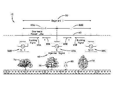
With respect to Fig. 2, in order to measure the high-frequency
impedance in one or more power lines 10, at least three sensors 20, which
are designated as, 20A, 20B and 20C, are spaced apart at a predetermined
distance along a segment 50/section of the power transmission line 10, which
has a predetermined length. However, in some embodiments the sensors
20A-C may be spaced apart from each other at any desired distance;
including distances that are equal or unequal to each other. It should be
appreciated that the power transmission line 10 includes an electrical
conductor, which serves as the physical layer for the transmission of
electrical current or energy loads. It is also contemplated that the power
transmission line 10 or power line may comprise any suitable power
transmission line, such as a high or low voltage overhead power transmission
line, an underground power transmission line, an indoor power transmission
line, or an electric railway power line system 25, such as the D.C. railway
power line system shown in Fig. 3, for example. In addition, the sensors 20A-
C are positioned in proximity with the power transmission line 10 so that they
are magnetically coupled (e.g. magnetic field coupling, inductive coupling)
with the power transmission line 10. As such, the sensors 20B and 20C,
which are configured as blocking sensors, are positioned at the end of the
transmission line segment 50, while sensor 20A, which is configured as a
detecting sensor, is positioned substantially in the middle of the
transmission
line segment 50. It should be appreciated that in the case of an electric
railway or train system 25, the blocking sensors 20B and 20C are positioned
at each terminal station 27, of a railway system, while the detection sensor
20A, which performs signal injection, may be placed anywhere between the
sensors 20B and 20C. It should be appreciated that in some embodiments
the electric railway system 25 may be a D.C. (direct current) railway system.
Next, a high-frequency signal 40 is injected, non-intrusively (i.e.
through the magnetic coupling, (such as magnetic field coupling or inductive
coupling for example) between the sensor 20A and the power transmission
line 10, into a midsection of the desired power line segment 50, by the smart
sensor 20A. The smart sensor 20A, which is configured to inject the high-
frequency signal, is positioned between the pair of blocking sensors 20B and
20C. As such, the injected signal 40 is transmitted along the power line
-7-
CA 02946139 2016-10-17
WO 2015/168260
PCT/US2015/028249
segment 50 from each end of the sensor 20A, such that one injected signal
40A propagates along half/or portion 60A of the power line segment 50 and is
then blocked by smart sensor 20B, while another injected signal 40B
propagates along half/or portion 60B of the power line segment 50 and is
then blocked by smart sensor 20C. Signal blocking sensors 20B and 20C
eliminate the effect of impedances that are connected to the segment 50
through blocking the high frequency currents. That is, performing the
blocking technique allows the impedance of the desired segment 50 of the
power transmission line 10 to be isolated from the impedance of the rest of
the power grid 12, and thus independently or separately measured. As such,
the impedance of the isolated power line segment 50 is calculated by the
sensor 20A by measuring the injected high-frequency voltage and the
resultant high-frequency current flowing in the power transmission line
segment 50. The determination or measurement of the impedance of the
power line segment 50 can be performed through hardware, software of a
combination of hardware electronics and the software programming on the
processors provided by the hardware, which may be provided by the sensors
or that may be provided remotely at a remote computer.
Thus, the signal blocking technique utilized by the present invention
20 provides sensors 20A-C that are magnetically coupled (e.g. magnetic
field
coupling, inductive coupling) to the power transmission line 10, which injects
a high-frequency signal into the power transmission line 10 by the detection
sensor 20A, which is then canceled by the blocking sensors 20B and 20C.
Thus, in contrast to existing high-frequency filtering methods, the method of
the present invention does not require any direct physical connection to the
overhead power line 20, instead, the sensors 20 of the present invention are
magnetically coupled (e.g. magnetic field coupling, inductive coupling) to the
power transmission line. Fig. 2 illustrates the arrangement of the non-
intrusive (i.e. magnetically coupled) sensors 20A-C that are used to measure
the high-frequency impedance of the desired power line segment, such as
segment 50. Each smart sensor 20A-C is capable of measuring the
impedance of the power line segment 50 in real-time. It should be
appreciated that while a group of three sensors 20A-C is needed to carry out
the monitoring functions of the present invention, any number of groups of
-8-
CA 02946139 2016-10-17
WO 2015/168260
PCT/US2015/028249
sensors may be used along the full length of the power transmission line 10
to monitor the performance of a plurality of segments to obtain impedance
measurements and power line/power grid health status with increased
precision or resolution.
The impedance of the power grid 12, when subject to the high-
frequency signal 40, is monitored by tracking the injected signal 40 via the
sensor 20A. As such, the difference between a pre-measured or stored
impedance of the section 50 of the power transmission line 10 being
monitored under healthy conditions (no faults), and the actual, or currently
measured impedance of the predetermined section 50 of the power
transmission line 10 being monitored provides information about the health of
the power line 10.
In addition, the sensors 20A-C may be configured to operate in
different modes. For example, as discussed above, the sensor 20A operates
to inject a high-frequency signal 40A-B, and to then detect the blocked
signals 2A-B, while sensors 20B and 20C operate as signal blockers, and
include stop filters that isolate the power grid 12 impedance from the
impedance of the power transmission line section 50 being monitored. As
such, the sensor 20A operates as a signal injector, which injects a high-
frequency signal into the power transmission line 10, while also acting as a
detection/monitor, thereby tracking or sensing the power line impedance
variation of the power line section 50 being monitored. The impedance of the
section 50 subjected to the high-frequency signal 40 is continuously
monitored and compared with the baseline impedance of the power line
section 50 to monitor the health of the power grid 12. Thus, because different
sections 50 of the power transmission line10 may be studied or monitored,
the sensors 20A-C may be selectively operated in any one of the
injection/detection mode or blocking mode discussed above to achieve the
monitoring of a particular power line segment 50 in the total length of a
given
power transmission line 10. It should be appreciated that the signal 40 may
be injected or the detection thereof may be performed periodically at any
desired pulse rate or time interval.
In addition, various electrical faults, that may affect the power
transmission line 10, are represented in Fig. 2, such as trees 70 and human
-9-
CA 02946139 2016-10-17
WO 2015/168260
PCT/US2015/028249
individuals 80 for example. That is, such faults are defined as the electrical
contact of the power transmission line 10 with a non-conductive surface like a
tree, animal, human body or any other non-conductive surface. However, the
present invention is configured to detect an electrical fault of the power
transmission line 10 that is the result of any structure or item coming in
contact with the transmission line 10.
Continuing to Fig. 4, the sensor 20, which is used to embody sensors
20A-C discussed above, includes a controller 100, which is configured with
the necessary hardware, software or combination thereof to carry out the
functions of the present invention discussed herein. The controller 100 is
coupled to a signal injection unit 102, which includes sine wave generators
110 and 120. The output of the sine wave generator 110 is coupled to a
driver 130, which is attached to a high-frequency transformer 132. The
transformer 132 includes a coupling coil 134 that is used to magnetically
couple (e.g. magnetic field coupling, inductive coupling) the sensor 20 to the
power transmission line 10. VHF denotes the high-frequency voltage that is
across the primary winding of the coil 134, and IHF is the high-frequency
current passing through the coil 134. In particular, the output of the sine
wave generator 110 is a VHF-CMND/command voltage signal that is applied
to the driver 130, which initiates the application of the injected VHF (i.e.
very
high frequency) signal into the power transmission line 10 via the magnetic
coupling established between the coil 134 and the power transmission line
10.
The output of the sine wave generator 120 is coupled to a sensing unit
150 that includes a pair of filters 200 and 210. Each filter 200 and 210
includes a series coupled band-pass filter component 212 and a low-pass
filter component 214. As such, the output of the band-pass filter component
212 of filter 200 is coupled at a node 216A to the input of the low-pass
filter
component 214, and whereby the output of the band-pass filter component
212 of filter 210 is coupled at node 216B to the input of the low-pass filter
component 214. That is, the output of the sine wave generator 120 is
coupled to nodes 216A-B positioned between the band-pass filter component
212 and the low-pass filter component 214 of each filter 200 and 210. The
output of each of the low-pass filter components 214 of the filters 200 and
-10-
CA 02946139 2016-10-17
WO 2015/168260
PCT/US2015/028249
210 are coupled to the controller 100. In addition, the input of the band-pass
filter component 212 of the filter 200 is a VHF-primary signal at line/wire
152,
and the input of the band-pass filter component 212 of the filter 210 is an
IHF-
primary signal at line/wire 154, whereby signals 152 and 154 are obtained
from the coil 134. The VHF-primary signal is the voltage induced across the
current sensing coil 134 and the IHF-primary is the current passing through
the coil 134. In one aspect, the VHF-primary signal is generated by the driver
130 based on the commanded signal from the controller 100. In the case of
the signal blockers 20B-C, the commanded voltage is calculated to be able to
block the high-frequency signal in the power transmission line segment 50
line. In the case of signal injector 20A the commanded amount is determined
so that injected high-frequency signal 40 is within the limits of standard
practices and electrical codes. Magnetic of the sensor 20 to the power
transmission line 10 is done through a magnetic core, having primary and the
secondary coils. The driver 130 is connected to a primary winding or coil
134, which has multiple turns, while the power transmission line 10, or
segment 50 thereof, is considered to be the secondary winding of the core.
In addition, the sensor 20 includes an in-series coupled energy
harvester 250, and energy storage device 252, such as an ultra- or super-
capacitor, and a DC/DC converter 254. The output of the DC/DC converter
254 is coupled to all other electronic components or blocks of the sensor 20,
including components 100, 110, 120, 130, 212, 216, and 214, so as to
provide power for such components to function. Typically, low-voltage levels
(e.g. 5V and 3.3 V) are required to be able to power all the electronics
circuits
in the sensor 20. The driver 130 is an electronic power amplifier, which
conditions the commanded signal from the controller 100 to be able to drive
the primary side of the HF transformer 132. It should be appreciated that any
commercial power amplifier can be used as the driver 130 to function as an
amplifier.
During operation of the sensor 20, when placed in an
injection/detection mode, such as in the case of sensor 20A discussed above,
the magnitude and phase of the signal 40 to be injected into the power
transmission line segment 50 is commanded by the controller 100 for receipt
by the sine wave generator 110. A block diagram of a control process 300
-11-
CA 02946139 2016-10-17
WO 2015/168260
PCT/US2015/028249
associated with the signal injection unit 102 is shown in Fig. 5. The
measured voltage and current received by the sensing unit 150 of the sensor
20A when operated in an impedance detection mode as a result of the
injected signal 140, (via coil 134) are passed by wires 152 and 154 through
the band-pass filter components 212 of the sensing unit 150 to generate
filtered signals. In order to extract the complex form of the measured voltage
and current, the filtered signals are each multiplied at nodes 216A-B of
respective filters 200, 210 by respective multipliers 240A-B by a phase
shifted
sine wave that is provided by sine wave generator 120. The signals output
by of the multipliers 240A-B are each low-pass filtered by the filters 214,
whereupon the signals are recorded by the controller 100. The amount of
phase shift that is applied to the multiplier 240 is swept to determine the
magnitudes and phases of the measured high frequency voltages and
currents. The complex form of the power transmission line impedance is then
determined based on the magnitude and phase of the injected voltage and
current. The amount of phase shift that is applied to the multipliers 240A-B
in
order to achieve the highest possible amplitude after the low pass filters 214
is what determines the actual phase of the voltage and current signals. The
complex form of the power line impedance at a higher frequency represents
the physical condition of the power line in real-time, which allows a model
for
the health condition of the power transmission line 10 to be obtained. The
impedance of the power transmission line 10 at a healthy condition is
measured, and taken as a reference value. The impedance of the power
transmission line 10 is monitored continuously, and is compared with the
reference impedance that is measured at previously determined or known
healthy conditions of the power transmission line 10. If the difference in
impedance is greater that a predetermined threshold value, then the sensor
20 alarms (notified/indicates) the operator of the power grid 12 about the
health condition of the power transmission line 10. This comparison may
occur at a remote computer, discussed below, or at the sensors 20
themselves.
It should be appreciated that the sensors 20 may include a wired or
wireless communication interface, which allows one or more sensors 20 to
communicate with each other, as well as allows the sensors 20 to
-12-
CA 02946139 2016-10-17
WO 2015/168260
PCT/US2015/028249
communicate with a local or remote computer system. The local or remote
computer system may be configured to analyze the data obtained from the
sensors 20, and generate the necessary alerts/reports prompts identifying the
health of the power transmission line 10 and/or power grid 12. In other
embodiments, the sensor 20 may generate the alert/report prompt indicating
the health status of the transmission line 10 or power grid 12. In addition,
the
sensor 20 or the remote computer, that are in communication with the
sensors 20 may communicate with a circuit breaker that controls the
application of electrical power to the power transmission line 10. As such,
the
sensor 20 or remote computer may command the circuit breaker to toggle
from an ON state or to an OFF state, or vice versa.
Therefore, one advantage of the present invention is that a smart
sensor network enables is non-intrusively coupled to a power transmission
line. Another advantage of the present invention is that a smart sensor
network the detection and monitoring of the impedance of a specific power
line segment to determine the overall health of a power transmission line.
Thus, it can be seen that the objectiveness of the present invention
have been satisfied by the structure and its method for use presented above.
While in accordance with the Patent Statutes, only the best mode and
preferred embodiments have been presented and described in detail, with it
being understood that the present invention is not limited thereto or thereby.
Accordingly, for an appreciation of the true scope and breadth of the
invention, reference should be made to the following claims.
-13-