Note: Descriptions are shown in the official language in which they were submitted.
CA 02946451 2016-07-26
WO 2015/112987 PCT/US2015/012930
CONVEYOR WITH NON-STICK SLATS
BACKGROUND
The present invention pertains to food processing systems, and in particular,
conveyors for processing food products designed so that the food products do
not readily
adhere to, or "stick to," the conveyor.
In industrial or commercial food processing systems, food products are carried
by
conveyors during the processing of the food products, including cooking, such
as during
frying or baking of the food products. Some food products tend to adhere to
the
conveyor, for example, coatings and seasoning used on food products, including
meat,
poultry, fish, vegetables, etc. Such coatings are primarily batter or
"tempura" but may
also include flour, breading, corn meal, panko, etc. When the food product is
removed
from the conveyor surface, the coating may be disturbed, causing the food
product to be
rejected.
To address the foregoing challenges in food processing, conveyors may be
constructed with cross slats composed of material that does not readily adhere
to, or
"stick to," typical food products, including coatings and seasonings. Such
cross slats
heretofore have been attached to the underlying drive chains or other conveyor
components by threaded fasteners to physically connect the slats (and perhaps
also
carriers with which the slats are engaged) to the drive chain or other
underlying structure
of the conveyor system. To prevent the fasteners from working loose and
unwanted
disassembly, the threaded fasteners are welded to the underlying chain or
other conveyor
structure. This results in the assembly of the conveyor being very labor-
intensive, and
thus expensive. Moreover, repair of the conveyor is difficult in that it is
necessary to cut
or otherwise remove the welded fasteners from the chain. The present
disclosure seeks to
address the foregoing and other shortcomings with respect to current slat-type
conveyor
construction, as well as address other technical issues.
SUMMARY
This summary is provided to introduce a selection of concepts in a simplified
form that are further described below in the Detailed Description. This
summary is not
intended to identify key features of the claimed subject matter, nor is it
intended to be
used as an aid in determining the scope of the claimed subject matter.
-1-
CA 02946451 2016-07-26
WO 2015/112987 PCT/US2015/012930
A conveyor belt assembly composed of links extending along the belt includes
slats disposed across the conveyor belt and attachment clips extending from
the conveyor
belt to encircle at least a portion of the slats, thereby to attach the slats
to the conveyor
belt.
In a further aspect of the present disclosure, the widths of the slats
correspond to
the pitch of the belt links, and preferably the slats are narrower than the
pitch of the belt
links to define a gap between adjacent slats.
In a further aspect of the present disclosure, the slats have portions
defining
grooves extending into and along the slats for engagement of the attachment
clips into the
grooves. In this regard, the clips can be generally C-shaped to include
flanged end
portions that are engageable into the grooves of the slats.
In a further aspect of the present invention, the slats are configured to
define a top
surface and side surfaces disposed laterally to the top surface. The grooves
are formed in
the side portions of the slat. The attachment clips are shaped to include free
end portions
that define flanges that are engageable into the grooves formed in the side
portions of the
slats.
In accordance with another aspect of the present invention, the slats are
composed
of a non-slick outer surface.
In accordance with another aspect of the present disclosure, the attachment
clips
encircle at least a portion of the conveyor belt links and extend from such
encircled
portion of the conveyor belt links to encircle at least a portion of the
slats, thereby to
attach the slats to the conveyor belt.
In accordance with a further aspect of the present disclosure, the conveyor
belt is
composed of sequential links connected by connection rods extending across the
belt to
interconnect longitudinally adjacent links. The attachment clips encircle one
or more of
the conveyor belt connection rods and encircle at least a portion of the
slats, thereby to
attach the slats to the conveyor belt. In a more specific aspect to the
present disclosure,
the attachment clips encircle a plurality of conveyor belt connection rods.
A slat assembly is mountable on a conveyor belt, the belt having a plurality
of
supporting elements extending across the belt. The slat assembly includes a
plurality of
slats extending across the belt, with the slats having a body portion and a
load-bearing
portion extending along the body portion. A plurality of attachment clips
encircle at least
-2-
CA 02946451 2016-07-26
WO 2015/112987 PCT/US2015/012930
a portion of the supporting elements of the conveyor belt and at least
partially encircle the
body portion of the slats to attach the slats to the conveyor belt.
In accordance with a further aspect of the present disclosure, the slats have
portions defining indentations therein. The attachment clips have portions
engaged
within the indentations of the slats. The indentations can be located in the
body portion
of the slats. Also, the indentations may be in the form of slots, grooves,
bores, or blind
bores.
In accordance with a further aspect of the present disclosure, the slat body
portions include side surfaces extending laterally from the load-bearing
surface of the
slats. The indentations are formed in the side surfaces of the body portion.
The
indentations are in the form of grooves formed in the side surfaces of the
slats to receive
portions of the attachment clips therein.
In accordance with a further aspect of the present disclosure, the body
portion of
the slats underlies the load-bearing surface of the slats. The attachment
clips partially
encircle the underlying body portion.
In accordance with a further aspect of the present disclosure, the support
elements
of the conveyor belt include a plurality of links extending across the width
of the belt.
The links are sequentially connected along the length of the conveyor by
connecting rods
extending transversely to the conveyor and intersecting adjacent links. The
attachment
clips encircle at least one transverse connecting rod of the conveyor belt and
at least
partially encircle the body portion of the slats to the conveyor belt.
DESCRIPTION OF THE DRAWINGS
The foregoing aspects and many of the attendant advantages of this invention
will
become more readily appreciated as the same become better understood by
reference to
the following detailed description, when taken in conjunction with the
accompanying
drawings, wherein:
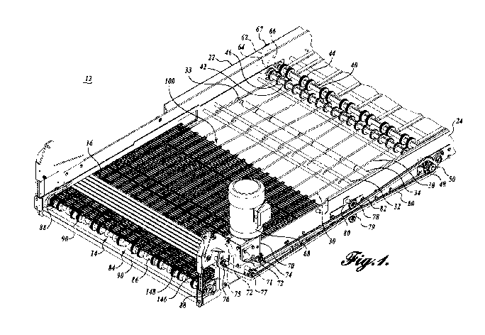
FIGURE 1 is a partial isometric view of the present disclosure;
FIGURE 2 is an enlarged fragmentary isometric view of the present disclosure;
FIGURE 3 is an enlarged partial cross-sectional view of the present disclosure
taken along lines 3-3 of FIGURE 2;
FIGURE 4 is an isometric view of a clip of the present disclosure;
-3-
CA 02946451 2016-07-26
WO 2015/112987 PCT/US2015/012930
FIGURE 5 is an enlarged cross-sectional view of a slat shown attached to a
conveyor belt using a clip of the present disclosure; and
FIGURE 6 is a view similar to FIGURE 5, showing an alternative embodiment to
the present disclosure.
DETAILED DESCRIPTION
While illustrative embodiments have been illustrated and described, it will be
appreciated that various changes can be made therein without departing from
the spirit
and scope of the invention.
The detailed description set forth below in connection with the appended
drawings, where like numerals reference like elements, is intended as a
description of
various embodiments of the disclosed subject matter and is not intended to
represent the
only embodiments. Each embodiment described in this disclosure is provided
merely as
an example or illustration and should not be construed as preferred or
advantageous over
other embodiments. The illustrative examples provided herein are not intended
to be
exhaustive or to limit the disclosure to the precise forms disclosed.
Similarly, any steps
described herein may be interchangeable with other steps, or combinations of
steps, in
order to achieve the same or a substantially similar result.
In the following description, numerous specific details are set forth in order
to
provide a thorough understanding of exemplary embodiments of the present
disclosure.
It will be apparent to one skilled in the art, however, that many embodiments
of the
present disclosure may be practiced without some or all of the specific
details. In some
instances, well-known process steps have not been described in detail in order
not to
unnecessarily obscure various aspects of the present disclosure. Further, it
will be
appreciated that embodiments of the present disclosure may employ any
combination of
features described herein.
The present application includes references to directions, such as "forward,"
"rearward," "upward," "downward," "extended," "advanced," and "retracted."
These
references and other similar references in the present application are only to
assist in
helping describe and understand the present invention and are not intended to
limit the
present invention to these directions. Also, references to "work product,"
"workpiece,"
"food product," "food piece," and "portion" are understood to be
interchangeable and are
not meant to be limiting in nature.
-4-
CA 02946451 2016-07-26
WO 2015/112987 PCT/US2015/012930
In the following description, various embodiments of the present disclosure
are
described. In the following description and in the accompanying drawings, the
corresponding systems assemblies, apparatus, and units are identified by the
same part
number but with an alpha suffix. The descriptions of the parts/components of
such
systems assemblies, apparatus, and units that are the same or similar are not
repeated so
as to avoid redundancy in the present application.
FIGURES 1 and 2 illustrate a flat wire conveyor 12 which is suitable for
effectuating the embodiments of the present disclosure. However, conveyors of
other
types may also be used in conjunction with the present disclosure. The
conveyor 12 is
designed to carry food products into fryers, ovens, or other types of
processing
equipment. The food product is supported on the conveyor 12 as the food
product is
introduced into the fryer, oven, etc., wherein a separate or different
conveying mechanism
may be utilized to continue to transport the product throughout the processing
station.
However, a conveyor similar to conveyor 12 may be utilized to transmit the
food product
throughout the fryer or other processing stations.
The conveyor 12 includes belt assembly 14 on which is mounted transverse slat
assemblies 16 on which the food product is transported. The slat assemblies 16
include
transverse slats or slat members 18 which are attached to the belt assembly
via connectors
in the form of clips 20; see, in addition, FIGURES 3, 4, and 5.
The conveyor 12 includes a frame composed of sidewall structures 22 and 24
extending longitudinally along the sides of the conveyor 12. The top run of
the conveyor
belt assembly 14 is guided and supported by guide rods 30 extending
longitudinally of the
conveyor and laterally spaced apart from each other. The guide rods 30 in turn
are
supported on cross rods 32. The belt returns underneath supported by cross
rods 33 over
which are journaled roller sections 34. The cross rods 32 and 33 span across
the width of
the conveyor to be supported by the sidewall structures 22 and 24.
The conveyor belt assembly 14 is powered by a drive system composed of a drive
shaft 42 that spans across the conveyor frame to be journaled relative to and
supported by
the conveyor frame sidewall structures 22 and 24. The drive shaft 42 supports
a plurality
of drive sprockets spaced apart along the length of the drive shaft. The drive
sprocket 44
meshes with the belt assembly 14, thereby to drive the belt assembly. A driven
sprocket 50 is attached to the portion of the drive shaft 42 extending
laterally outwardly
from frame sidewall structure 24 to engage an endless drive chain 60. An idler
-5-
CA 02946451 2016-07-26
WO 2015/112987 PCT/US2015/012930
sprocket 48 is provided to maintain the chain wrap, provide appropriate chain
tension,
and avoid chain-to-chain collision. The chain 60 is driven by a drive motor 68
via a gear
box 70. A drive sprocket 75, powered by the gear box, meshes with the drive
chain 60.
Also, various idler sprockets 71, 72, 74, 76, and 77 guide the chain 60
towards and away
from the powered drive gear 75. A pair of upper and lower idler sprockets 78
and 79
support and constrain the upper and lower runs of the drive chain 60 at a
location
generally centrally along the upper and lower runs of the belt. The idler
sprockets 78 and
79 are antifrictionally journaled on stub shafts 80 extending outwardly from a
bracket 82
mounted to the outer side portion of frame sidewall structure 24; see FIGURE
1.
Although the manner in which the belt assembly 14 can be driven has been
described
with specificity, it is to be understood that the belt assembly also can be
driven by many
other systems.
At the entrance end of conveyor 12, the conveyor belt assembly 14 trains
around
an idler sprocket assembly 84 composed of an idler shaft 86 that spans across
the width of
the conveyor frame to be supported and journaled by bearing assemblies 88
carried by the
conveyor sidewall structures 22 and 24. A plurality of idler sprockets 90 are
mounted on
the shaft 86 to mesh with the links of the conveyor belt assembly 14, as
described more
fully below.
The conveyor belt assembly 14 includes a belt 100 composed of formed flat wire
links 102 that extend across the width of the belt 100. Adjacent links 102 are
connected
together by cross rods or cross pins 104.
Each link 102 includes transverse sections 106 divided by formed wedge-shaped
segments 108. Each of the wedge-shaped segments includes opposite leg sections
110
extending laterally from transverse sections 106 to intersect an end section
112. The
width separating the leg sections 110 is narrower at the end sections 112 than
at the
intersections of the leg sections with transverse sections 106, thereby
forming the
generally wedge-shaped segments 108. As shown in FIGURE 2, the wedge-shaped
segments 108 of the adjacent links 102 nest with each other.
The cross rods 104 extend through slots 114 formed in the leg sections 110 of
the
wedge-shaped segments 108. A slot 114 is located in the leg section 110
adjacent
corresponding end section 112, as well as adjacent corresponding transverse
section 106.
This enables the cross rod 104 to extend through a slot 114 adjacent
transverse
section 106 and then through a slot 114 of the next adjacent link 102 located
near the end
-6-
CA 02946451 2016-07-26
WO 2015/112987 PCT/US2015/012930
section 112 of such next adjacent link 102. It will be appreciated that the
slots 114 can
accommodate misalignment between the slots of the adjacent links 102, and can
also
allow the belt assembly 14 to follow a curved path, if need be.
As shown in FIGURE 2, the teeth of idler sprockets 90 mounted on shaft 86
engage with either the transverse sections 106 or the wedge end sections 112
of the belt
links 102 to wrap the belt 10 at the end of the conveyor 12. The teeth of the
drive
sprockets 46 engage the bar links 102 in the same manner as the teeth of idler
sprockets 90.
Referring to FIGURE 1, the conveyor belt assembly 14 does not extend the full
length of the conveyor 12, but rather extends between idler sprocket assembly
84 and
drive shaft 42. A second conveyor belt (not shown) that may be of a
conventional
construction is used to carry the food product further through the processing
station. By
the time that the food product reaches the second conveyor, the food product
has been
sufficiently processed that it no longer tends to adhere to the conveyor 14.
The second
conveyor belt is driven by the drive shaft 40 that extends laterally across
the conveyor
frame parallel to drive shaft 42. A plurality of sprockets 44 are mounted on
the drive
shaft 42 to engage the second, perhaps conventional, conveyor belt. The drive
shaft 40 is
driven by drive shaft 42 via drive chain 62 that engages sprockets 64 and 66
attached to
the portions of the drive shafts 42 and 40, respectively, located outwardly of
the frame
sidewall structure 22. An idler sprocket 67 is positioned between the
sprockets 64
and 66.
Next, referring specifically to FIGURES 3, 4, and 5, the slat assemblies 16
include individual slats 18 that are generally rectilinear in cross section.
The slats 18
include a top cap portion 130 that overlies a lower body portion 132. Slots
134 are found
in the slats 18 to extend laterally into the slat and longitudinally along the
slat at a
location between the cap portion 130 and body portion 132, at the intersection
of the cap
portion and body portion. As shown in FIGURE 5, the cap portion 130 somewhat
overhangs the sides of the body portion 132. Also, the intersection between
the top
surface of the cap portion 130 and the side edge of such cap portion is
beveled or
chamfered, which matches historical slat profiles and aids in product release.
The underside of the slat body portion 132 is held against the top edge of the
conveyor belt links 102 by attachment clips 20. The clips 20 are generally in
the shape of
a rectilinear "C." The clips include a base portion 140 that underlies the
links 102,
-7-
CA 02946451 2016-07-26
WO 2015/112987 PCT/US2015/012930
upright web sections 142 extending upwardly through links 102, and inwardly
directed
upper flange portions 144 that are shaped and sized to closely engage into
slots 134. The
upright web sections 142, by extending upwardly along the sides of the body
portion 132
of the slats 18, and the flange portions, by engaging into slots 134,
cooperatively,
partially surround the body portion 132 of the slat 18. Also, the upright web
sections 142
extend beneath and partially around, and thus partially encircle and capture,
adjacent
cross rods 104 and corresponding transverse sections 106 of belt links 102. In
this
manner, the clips 20 retain and position the slats 16 relative to a specific
belt link 102.
As shown in FIGURE 2, the clip 20 encircles two adjacent cross rods 104 and
link
transverse sections 106. As such, each of the slats 116 corresponds to one
pitch of the
conveyor belt 100. Also, it will be appreciated that the clips 20 hold the
slats 16 securely
but not necessarily against the upper edge of the belt links 102. By not
holding the slat
tightly against the belt link, belt assembly 14 is allowed to articulate more
freely around
drive and idler sprockets.
As shown in FIGURES 2, 3, and 5, the lengths "L" of clips 20 are selected to
almost correspond to the lengths of belt link transverse sections 106. As
such, the
slats 16 are held substantially stationary relative to the conveyor belt 100
in a direction
lengthwise of the slats. Of course, if different types of links are used to
construct belt
100, then the length "L" of clips 20 can be adjusted accordingly. Also as
shown in
FIGURES 1-3, the widths of the slats 16, and in particular the widths of the
cap
portion 130, are selected so that there is a gap between adjacent slats 16
when mounted
on belt 100. This enables food product material to fall down through the
slats, for
example, breading material that sloughs off food products being processed.
Moreover,
such gaps enable processing fluids, such as cooking oil, to pass between the
slats for
circulation relative to the belt 100 and the food products being carried on
the belt.
The above description specifies that the clips 20 "extend" upwardly from
links 102. Of course, this does not mean that the clips are physically secured
to the links,
for instance, by weldments.
The slats 16 are preferably formed from material that does not readily adhere
to or
stick to typical food products, such as coatings used with poultry, meat,
fish, vegetables,
etc. Such coatings are primarily batter or "tempura" but may also include, for
example,
breading, corn meal, flour, panko, etc. Materials meeting the foregoing
requirements
include any of the family of FDA-compliant Polytetrafluoroethylene (PTFE). In
this
-8-
CA 02946451 2016-07-26
WO 2015/112987 PCT/US2015/012930
regard, the entire slat 16 can be composed of PTFE material or other suitable
durable
"non-stick" material, such as Polyether ether ketone (PEEK).
Due to the fairly harsh operating environment of the conveyor 12, it is
desirable
that the clips 20 be made from a material, and of a thickness, that is
structurally capable
of securely maintaining the slats attached to the conveyor belt 10, even in
high operating
temperatures. In this regard, the composition of clip 20 should take into
consideration
that the thermal expansion coefficient of the slats may differ substantially
with respect to
the thermal expansion coefficient of clip 20. One suitable material for the
clips 20 is
stainless steel. Other metallic or non-metallic material may be utilized.
The foregoing construction of clips 20 facilitates the installation of the
slats 18 on
the conveyor belt 100. In this regard, as shown in FIGURES 1 and 2, the clips
20 may be
positioned to span between adjacent transverse sections 106 of adjacent links
102. Then
the slats may be installed by sliding the slats laterally relative to the
conveyor belt 10 to
engage the clip flange sections 144 into the slots 134 formed in the slats 18.
Openings 146 are formed in brackets 148 attached to the end portions of the
conveyor
sidewall structures 22 and 24 through which the slats 18 may be passed during
assembly
and disassembly from conveyor belt 10. Of course, one or more openings can be
formed
in other locations along the conveyor sidewall structures 22 and/or 24 for
sliding
assembly and disassembly of the slats 18 with the clips 20.
An alternative embodiment to the present disclosure is illustrated in FIGURE
6,
wherein the corresponding parts of the conveyor belt are given the same
numbers as in
FIGURES 1-3 and 5 above, and the corresponding parts of the slat and clip are
given the
same part numbers as in FIGURES 1-5 but with an alpha suffix. As shown in
FIGURE 6,
slat 16A is similar in construction to slat 16 in that the slat 16A includes a
cap
portion 130A and a body portion 132A. The body portion 132A differs from body
portion 132 in that the upper corners of the body portion 132A are rounded or
radiused to
form a rounded shoulder rather than being of a rather sharp corner in the
manner of body
portion 132. Consequently, the flange portion 144A of clip 20A is rounded or
radiused to
correspond to the rounded shoulder 150 of slat 16A. Other than in this regard,
the
slats 16 and 16A and clips 20 and 20A of FIGURES 5 and 6 are substantially the
same
and provide substantially the same advantages.
Although clips 20 and 20A have been shown as generally of a rectilinear
C-shaped structure, slats similar to slats 16 can be mounted on conveyor belt
100 by other
-9-
CA 02946451 2016-07-26
WO 2015/112987 PCT/US2015/012930
systems. For example, rather than utilizing clips having a length "L" to
correspond to the
length of belt link transverse sections 106 as shown in FIGURE 4, shorter
clips may be
utilized. Moreover, rather than being of a rectilinear length as shown in
FIGURE 4, the
clips can be made from wire material with the profile shown in FIGURES 5 and
6. In
this regard, such wire clips or pins can engage within slots similar to slots
134 formed in
the slats 16 and 16A. Alternatively, blind holes can be formed in the slats 16
and 16A to
receive the ends of the wire clips/pins.
Although clips 20 and 20A, as well as wire clips/pins, have been described
above
as being of separate construction from conveyor belt 100, either such clips
may be fixedly
attached to the conveyor belt or the conveyor belt may be manufactured or
constructed
with integral clips of the nature described above. Such integral construction
of the clips
with the conveyor belt may include conveyor belts of a flat wire construction,
as
described above, or conveyor belts of other constructions.
While illustrative embodiments have been illustrated and described, it will be
appreciated that various changes can be made therein without departing from
the spirit
and scope of the invention. For example, the clips 20 and 20A as well as the
pin-type
clips disclosed above for attaching the slats 16 to the conveyor belt are
described as
encircling, and thus capturing, adjacent cross rods 104 and transverse
sections 106 of the
belt link 102. However, the clips and attachment pins may instead encircle
and/or capture
other portions of the conveyor belt, especially if the conveyor belt is of a
different
construction than the belt 100 described above. In this regard, slats 16 may
be mounted
on the conveyor belt without the need for the use of fasteners, such as
screws, rivets, or
similar hardware, which make assembly and disassembly of the slats from the
conveyor
belt cumbersome and very time-consuming.
As a further matter, although the attachment structures 20 and 20A have been
designated as "clips," such structures could also be referred to by other
designations, such
as guides, fasteners, or retainers, without departing from the scope of the
present
invention.
Also, it will be appreciated that although the slat assemblies and conveyer
belts
constructed with the disclosed slat assemblies are useful to transport food
products that
otherwise might adhere to conventional conveyors, it can be appreciated that
the
disclosed slat assembly, and conveyors composed thereof, can be used with
other types of
-10-
CA 02946451 2016-07-26
WO 2015/112987 PCT/US2015/012930
food products or for other purposes than specifically described above, or even
used to
transport work products other than food products.
In addition, although one construction with conveyor belt 100 has been
described
above, it is to be understood that the conveyor belt can be of a construction
considerably
different than described. In this regard, it is desirable that the belt has a
continuous pitch.
Also, to match existing conveyor belts and so that stock material can be used
to construct
clips 20 and 20A, it can be helpful if the pitch of the belt links 102 is an
even design of
1 inch.
-11-