Note: Descriptions are shown in the official language in which they were submitted.
CA 02946675 2016-10-27
1
A Core Release System and Method
Technical Field
A core release system and method is disclosed for facilitating the removal of
a core
sample from a tube such as core lifter case or like mechanism.
Background Art
During core drilling (also known as diamond drilling) an inner core tube
assembly is
releasably locked at a downhole end of a core drill. The inner core tube
assembly
includes a core tube and a core lifter assembly fitted to an end of the core
tube. The
core lifter assembly comprises a core lifter case and a core lifter spring. An
outer
circumferential surface of the core lifter spring and an inner circumferential
surface of
the core lifter case are formed with a complementary taper. As a result of the
tapered
surfaces, relative axial motion between the spring and the case results in a
reduction
or increase in the inner diameter of the core lifter spring.
During drilling as a core sample is cut it progresses through the core lifter
spring and
core lifter case and into the core tube. Due to the orientations of the
tapered
surfaces on the spring and the case, the spring is displaced into an up-hole
region of
the core lifter case allowing it to expand radially to the extent necessary to
allow the
core sample to travel into the core tube.
During a core break the drill string is lifted in an up-hole direction. This
causes the
core lifter spring to move in a downhole direction relative to the core lifter
case so
that the tapered surfaces act to clamp the core lifter spring onto an outer
circumferential surface of the core sample. This grips the core sample and
transmits
the upward pulling force onto the core sample breaking it from the adjacent
strata.
The inner core barrel assembly can now be retrieved typically using a wire
line. In
order to allow inspection of the core sample it must be removed from the core
tube.
Usually the core sample is tightly gripped in the core lifter case by the core
lifter
spring. To release the grip it is necessary to displace the core lifter spring
so as to
travel within the core lifter case to a location where the taper of the case
enables the
core lifter spring to resiliently expand to release its grip on the core
sample.
Prior to taking this step a geologist will often mark a portion of the outer
surface of
the core sample which protrudes from the core lifter case with an indication
of the
location of a specific bearing such as the bottom of a hole. This is often
done by use
of a pencil or scratching tool.
CA 02946675 2016-10-27
2
A common technique for displacing the core lifter spring to release the sample
form
the core lifter case is to strike a protruding portion of the core sample with
a hammer.
In an alternate technique the core tube with the attached core lifter assembly
can be
dropped onto the ground or impacted with a solid surface with the core sample
leading.
While these techniques do result in releasing the core sample from the grip of
a core
lifter case they also often result in damaging or breaking of the end of the
core
sample. This may also or alternately result in the loss of the orientation
reference
from the core sample.
The above Background Art is not intended to limit the application of the
system and
method as disclosed herein.
Summary of the Disclosure
In one aspect there is disclosed a core release system comprising: a housing
provided with an impact member, the housing capable of receiving an end of a
tube
in which a core sample is gripped, the system arranged so that on applying a
force to
cause impact between the core sample and the impact member the core sample is
displaced relative to the tube.
In one embodiment the impact member is arranged to deform in preference to the
core sample.
In one embodiment the impact member comprises a material which is softer than
material constituting the core sample.
In one embodiment impact member is configured to fit within the tube.
In one embodiment impact member is provided with an impact face configured to
impact with the core sample at a location inboard of a circumferential
peripheral
edge of the core sample.
In one embodiment the impact member includes a shock absorbing mechanism.
In one embodiment the impact member is movably mounted on the housing wherein
the force displaces the impact member relative to the housing.
In one embodiment the housing is arranged to enable self-supported coupling to
the
tube.
In one embodiment the system comprises a coupling mechanism arranged to
facilitate coupling of the housing with the tube enabling the housing to be
self-
supported on the tube.
CA 02946675 2016-10-27
3
In one embodiment the coupling mechanism is arranged to allow the housing to
move relative to the tube in response to application of the force.
In one embodiment the coupling mechanism includes one or more magnets provided
on one or both of the housing and the tube.
In one embodiment the coupling mechanism comprises a resilient member
configured to act between an inside surface of the housing and an outer
surface of
the tube.
In one embodiment the resilient member comprises an 0-ring supported inside of
the
housing.
In one embodiment the coupling mechanism comprises a cam lock mechanism
arranged to operate by relative rotation between the housing and the core
lifter case.
In one embodiment the system comprises a visual indicator arranged to provide
a
visual indication to a user of the system of an amount of displacement of a
core
sample into the tube subsequent to being impacted with the impact member.
In one embodiment the visual indicator is a window formed in the housing at a
location enabling viewing of the impact member.
In one embodiment the window is further configured to enable visualisation of
the
tube at least when impact between the core sample and the impact member has
displaced the core sample into the tube a distance sufficient to release
sample from
the grip of the tube.
In one embodiment the window and the impact member are arranged so that when
the core sample has been displaced the sufficient distance only the core tube
is
visible through the window.
In one embodiment the housing comprises a sleeve and a cap demountably coupled
to an end of the sleeve, the impact member being coupled to the cap.
The tube in relation to which the disclosed system may be applied includes but
is not
limited to: a core lifter case; a core tube; and, a core tube to which a core
lifter case
is attached.
In another aspect there is disclosed a method of releasing a core sample from
a
tube, the method comprising: locating a housing over an end of the tube in
which a
core sample is gripped; and impacting the core sample with an impact member
carried by the housing.
In one embodiment the method comprises arranging the impact member to deform
when impacted by the core sample.
CA 02946675 2016-10-27
4
In one embodiment the method comprises forming at least a portion of the
impact
member from a material that is softer than the core sample.
In one embodiment the method comprises configuring the impact member to fit
inside of the tube.
In one embodiment the method comprises impacting the core sample with the
impact
member at a location inboard of a circumferential peripheral edge of the core
sample.
In one embodiment locating the housing over an end of the tube comprises
coupling
the housing to the tube in a self-supporting manner.
In one embodiment coupling the housing comprises magnetically coupling the
housing to the tube.
In an alternate embodiment coupling the housing comprises mechanically
coupling
the housing to the tube.
In one embodiment the method comprises providing a visual indicator indicative
of
an amount of displacement of the core sample into the tube as a result of the
impacting.
In one embodiment the impacting comprising repeatedly impacting the core
sample
with the impact member until the visual indicator provides an indication that
the core
sample has been displaced a distance sufficient to release the core sample
from the
grip of the tube.
In one embodiment impacting comprises dropping, knocking or thrusting the core
tube with the coupled housing onto a surface in a manner wherein an end of the
housing contacts the surface.
The tube in relation to which embodiments of the disclosed method may be
applied
can include but is not limited to: a core lifter case; a core tube; and, a
core tube to
which a core lifter case is attached
One embodiment the disclosed system may comprise: a housing provided with an
impact member, the housing being capable of self-supported coupling to an end
of a
tube in which a core sample is gripped, the system arranged so that on
applying a
force to cause impact between the core sample and the impact member the core
sample is displaced relative to the tube.
Another embodiment of the disclosed system may comprise: a housing provided
with
an impact member, the housing capable of receiving an end of a tube in which a
core sample is gripped, the system arranged so that on applying a force to
cause
impact between the core sample and the impact member the core sample is
displaced relative to the tube; and a visual indicator arranged to provide a
visual
CA 02946675 2016-10-27
indication to a user of the system of an amount of displacement of a core
sample into
the tube subsequent to being impacted with the impact member.
Brief Description of the Drawings
5 Notwithstanding any other forms which may fall within the scope of the
system and
method as set forth in the Summary, specific embodiments will be now described
by
way of example only with reference to the covering drawings in which:
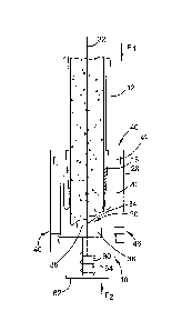
Figure 1 is a section view of a representation of the disclosed core release
system together with a section view of a lower end of a core tube and
associated
core sample;
Figure 2 is a section view of the core removal system when self-supported on
an end of the core tubes;
Figure 3 is a side view of a housing of the core release system prior to
operation of the core release system to release the core sample;
Figure 4 is a section view of the core release system, core tube and core
sample subsequent to operation of the core release system to release the core
sample from the core tube; and
Figure 5 is a side view of the housing of the core release system upon
operation as shown in Figure 4.
Detailed Description of Specific Embodiment
Figures 1 and 3 depict a section and side view respectively of an embodiment
of the
disclosed core release system 10. In Figure 1 the core release system 10 is
shown
in conjunction with a section view of a tube in the form of a core tube 12
fitted at a
lower end with a core lifter assembly 14 and captured core sample 16. The core
lifter assembly 14 comprises a core lifter spring 18 which is located inside a
core
lifter case 20. The core lifer case 20 is screwed onto an end of the core tube
12.
The core sample 16 is firmly gripped by a core lifter spring 18 which acts as
a wedge
between the core sample 16 and an inner tapered surface 22 of a core lifter
case 20.
The core sample 16 is also shown with a representation of bottom of hole mark
24
applied to an outer surface at an exposed end 26 of the core sample 16.
In order to release the core sample 16 from the core lifter case 20 and the
assembly
14 it is necessary to displace the core lifter spring 18 relative to the case
20 so that
the spring 18 resides in a widened inner diameter portion of the case 18
created by
the tapered surface 22. In the prior art this is often achieved by hitting the
end 26 of
CA 02946675 2016-10-27
6
the core sample 16 with a hammer. This displaces the core sample 16 together
with
the core lifter spring 18 in the direction of the tube 12 thereby releasing
the grip of
the spring 18. However as previously described this can and often does damage
the
end 26 including to the extent of losing the bottom of hole position reference
mark
24.
Embodiments of the disclosed core release system 10 provide an alternate way
for
releasing a captured core 16 in a manner which minimises damage to the core
sample 16 while also enhancing safety in the removal process.
The core release system 10 comprises a housing 28 provided with an impact
member 30. Some embodiments of the system 10 are arranged so that the housing
28 is capable of self-supported coupling to the core lifter case 20. The
coupling may
be directly on the or to the case 20 or alternately on or to the core tube 12
to which
the case 20 is attached. This is shown for example in Figure 2.
By being coupled in a self-supporting manner the system 10 can be retained on
an
end of the core tube 12 while the core tube 12 is being handled or otherwise
manipulated without the need for an operator/user physically holding the
housing 28.
Thus for example the core tube 12 with the coupled self-supported system 10
can be
lifted or held vertically off the ground with the system 10 lower most without
it falling
off. This arrangement is shown for example in Figure 2.
By being self-supporting the system 10 has an inherent level of safety over
use of
say a hammer to release a core sample. Using a hammer is problematic as it can
lead to injury when for example the hammer skids off or rebounds from the core
sample 16. Also by being self-supporting a user need not hold the system 10
onto
the end of a core tube 12 while also trying to hold onto and manipulate the
core tube
itself. Trying to do so would not only be awkward with an industry standard
three
meter long core tube 12, but it would be dangerous with the chance of impact
an
operator's hand if the two items misaligned, or if a flying rock chip hits the
operator's
eye due to the head of the operator being in close proximity to the impact
point.
The system 10 is arranged so that on applying a force to cause impact between
the
core sample 16 and the impact member 30 the core sample 16 is displaced
relative
the core lifter case 20. More particularly the sample 16 is displaced in a
direction
further into the case 20, i.e. in the direction of the core tube 12. The force
is applied
along a central axis 32 of the tube 12 and the coupled system 10. The force
may be
applied from the side of the tube 12 shown as force Fl in Figure 2; or from
below the
housing 28/impact member 30 shown as force F2 in Figure 2.
Of course, irrespective of the direction of application the other force will
be
automatically generated as an equal and opposite force in accordance with
Newton's
third law of motion. Most conveniently, the force is applied by holding the
core tube
12 with the system 10/housing 28 coupled to the case 20 and then driving tube
12
with the housing 28 first onto a firm surface. The firm surface could be for
example
CA 02946675 2016-10-27
7
the ground or a mine wall. This action may be required to be repeated several
times
in order to fully release the core sample 16 from the case 20.
In order to prevent or at least minimise damage to the end 26 of the core
sample 16
the impact member 30 is arranged to deform or otherwise absorb energy in
preference to the core sample 16. The deformation of the impact member 30 may
be result of a property of the material from which the member 30 is made
and/or by
the provision of a shock absorber. For example the material may be one which
is
elastically or plastically deformable; or in the case of a shock absorber, may
include
a mechanical spring or a layer or portion of resilient material between an
upper face
34 of the impact member 30 and the housing 28. In the present embodiment the
impact member 30 comprises a rubber block 36 mounted on top of a block 38 made
from a plastics material. The rubber block 36 in this instance deforms on
impact with
the core sample 16.
The impact member 30 is configured to fit within the core tube 12. This is
shown for
example in Figure 4. As explained later this enables the impact member to
enter the
core lifter case 20 during operation of the system 10. Further the face 34 of
the
impact member 30 is configured to impact with the core sample 16 at a location
inboard of a circumferential peripheral edge of the core sample 16. Thus no
impact
force is applied to the peripheral circumferential edge of the sample 16.
Rather all
the impact force is directed to a central region of the core sample 16. This
assists in
minimising or totally avoiding any damage to the sample 16 including
fracturing.
The system 10 has a coupling mechanism 40 arranged to facilitate coupling of
the
housing 28 with the core tube 12 enabling the housing 28 to be self-supported
on the
core tube 12. In this embodiment the coupling mechanism 40 is also arranged to
enable the impact member 30 to move linearly relative to the case 20 in
response to
application of the force. In this particular embodiment this is achieved by
providing
the coupling mechanism 40 as one or more magnets 42. The magnets 42 are
embedded in a cylindrical wall 44 of the housing 28. The inner diameter of the
wall
44 is greater than the outer diameter of the case 20 so that there is or can
be a small
annular gap created there between. This assists in minimising friction and
enabling
easy movement of the system 10 and more particularly the impact member 30
relative to the case 20.
The system 10 is provided with a visual indicator 46 which is arranged to
provide a
visual indication to a user of the system 10 of an amount of displacement of
the core
sample 16 relative to and more particularly into the core lifter case 20. In
this
particular embodiment the visual indicator 46 comprises a plurality of windows
48
formed in the cylindrical wall 44 of the housing 28. The windows 48 are
located to
enable viewing of the impact member 30 before the system 10 is coupled to the
case
20 and/or when coupled but prior to application of the impact force.
CA 02946675 2016-10-27
8
Figures 2 and 3 illustrate the relative juxtaposition of the system 10 and
case 20
when coupled together but prior to application of an impact force. In this
juxtaposition the face of the sample 16 may be abutting or very close to the
face 34
of the impact member 30. A person utilising the visual indicator 46 viewing
through
the window 48 will be able to see the impact 30. This indicates that there has
been
no displacement of the core sample 16 relative to the casing 20.
Figures 4 and 5 on the other hand illustrate the juxtaposition of the system
10 and
case 20 after one or more applications of the impact force. When the impact
force is
applied the core sample 16 and lifter spring 18 are initially moved together
relative to
the case 20 in a direction into the tube 12. As this occurs the downhole end
of the
casing 20 moves over the impact member 30 as the impact member 30 moves into
the case 20. As a result the impact member 30 is progressively covered by the
casing 20. Thus now the case 20 is visualised through the window 48.
The impact member 30 is dimensioned so that it's complete shrouding by the
case
20 as shown in Figures 4 and 5 is indicative of the spring 18 and sample 16
being
displaced a sufficient distance to enable the spring 18 to expand radially
outward so
as to release the grip of the core 16 to the case 20. Thus in use a user will
apply the
impact force for as many times as required so that the impact member 30 is
fully
covered by the case 20. This can be visualised through the window 48 and
provides
an indication that the core sample 16 has been released from the grip of the
core
lifter assembly 14.
Whilst a specific system and method embodiment have been described it should
be
appreciated that the system and method may be embodied in many other forms.
For
example the attachment mechanism 40 is described as comprising one or more
magnets 42. However alternate coupling mechanisms may be used. These include
for example, but not limited to, one or more resilient members that act
between the
housing 28 and the case 20 and/or tube 12 to provide a friction fit or
coupling there
between. A specific example of this is a rubber 0-ring retained in the inner
circumferential surface of the housing 28. A further alternative is forming
the coupling
mechanism 40 as a cam lock system. This may operate by rotating for example
the
housing relative to the case 20/tube 12.
Further, it should be understood that it is not absolutely necessary for the
housing 28
to be coupled in a manner that allows it to move relative to the case 20. In
order to
transmit the impact force all that is required is for the impact member 30 to
move
relative to the case 20. This may be achieved for example by, with reference
to
Figure 4, mounting the impact member 30 on a post 60 which extends through the
base 50 so that the impact member 30 can slide in axial direction of the post
60
relative to the housing 28. The post 60 is provided with an impact plate 62 at
one
end with a spring 64 being retained between the plate 62 and the base 50. Thus
in
this embodiment the housing 28 can be coupled to the case 20 and/or tube 12
with
CA 02946675 2016-10-27
9
the impact member 30 butting or closely adjacent to the end 26 of the core 16
as
shown in Figure 2.
The use of this modified embodiment of the system 10 is the same as described
above the only difference being now that the impact force causes the impact
member 30 to lift off the inside surface of the base 50 in order to displace
the spring
18 and core 16. In this embodiment the visual indicator may simply comprise
the
juxtaposition of the plate 62 to base 50. In particular the post 60 can be
dimensioned so that the abutment of the plate 62 with the base 50 provides the
visual indication that the core 16 has been released from the case 20.
Additionally when the impact member 30 comprises a layer or portion of
resilient
material between an upper face 34 of the impact member 30 and the housing 28,
it is
not essential that the resilient material is upper most and constitutes the
face 34. For
example it is possible for the block 38 to be mounted on top of the rubber
block 36.
In such an embodiment the face 34 would be constituted by the block 38.
Nonetheless the impact member 30 still provides protection to the core sample
16 by
action of the resilience and shock absorbing properties of the rubber block
36.
The described embodiments of the core release system and method are described
in
the context of core drilling where the tube can be considered to be the core
tube, the
core lifter case or the ensemble of a core tube and a core lifter case.
However the
disclosed system and method may be applied and used without modification to
any
tube in which a core sample or indeed any article is gripped in a way where
the grip
can be released by linearly moving the article relative to the tube.
In the claims which follow, and in the preceding description, except where the
context requires otherwise due to express language or necessary implication,
the
word "comprise" and variations such as "comprises" or "comprising" are used in
an
inclusive sense i.e. to specify the presence of the stated features but not to
preclude
the presence or addition of further features in various embodiments of the
system
and method as disclosed herein.