Note: Descriptions are shown in the official language in which they were submitted.
CA 02947430 2016-10-28
WO 2015/171568 PCT/US2015/029180
1
SKYLIGHT WITH MANUAL CLOSING FEATURE
RELATED APPLICATIONS
This application claims the benefit of pending U.S. Prov, Appl. Ser. No.
61/988,780, filed on May 5, 2014, the contents of which are hereby
incorporated by
reference herein.
FIELD OF THE INVENTION
The current invention relates to the field of skylights and roof hatches, more
specifically to a skylight that allows for controlled incremental manual
opening and
closing.
BACKGROUND OF THE INVENTION
Skylights are becoming increasingly popular in homes and businesses. Some
skylights are large and heavy and, as a result, they cannot be opened and
closed using
manual strength. Mechanical assistance is required to open and close these
heavy
skylights. To that end, many such skylights are operated by hydraulics or
air/gas
pressure. For example, skylights may be powered by an air compressor which
pumps
air to move an arm in order to open the skylight and it releases air to lower
the arm.
One problem with prior systems of opening and closing such skylights is that
they
require electric power. Thus, if there is a blackout or shortage in electrical
power supply
¨ the skylights cannot be operated. This can be especially troublesome in the
event that
a large skylight is open and then power is lost ¨ potentially putting a
homeowner at risk
of his/her house becoming flooded by rain or snow. Moreover, in order to
operate
skylights with hydraulics or air compression ¨ hoses must be run from a
compressor
unit to the skylight. It requires extensive work to run hoses from a
compressor that is
usually housed in a basement to the skylight unit. Such efforts are even more
difficult
when attempting to retrofit an existing structure with a skylight, and the
hoses and
switches must be buried inside existing finished wall surfaces. Still further,
a
homeowner or business owner may want to install a skylight in an area that is
outside
the range of an electric power source.
The invention described herein addresses the need for a large-sized skylight
or
roof hatch that is operated by manually controlled mechanical elements without
the
need of electricity.
CA 02947430 2016-10-28
WO 2015/171568 PCT/US2015/029180
2
SUMMARY OF THE INVENTION
The skylight described herein has attached gas springs that are used to open
the
window. The gas springs bias the window toward an open position, such that
when the
biasing force becomes unopposed by a counter force ¨ the window is forced
open. A
cable that is wound around a cable reel provides opposing force to keep the
window
closed.
Once the window is open, the cable reel is turned several rotations to wind
the
cable and incrementally close the window. Winding the cable around the reel
overcomes the biasing force created by the gas springs and doing so closes the
window.
A chain attached to a pulley wheel is used to open and close the window
through
associated mechanical linkages. When the pulley wheel is rotated in one
direction,
associated mechanical linkages release the cable reel allowing for the window
to open.
When the pulley wheel is rotated in the opposite direction, the connected
cable reel is
turned to wind the cable around the cable reel and thereby force the window
closed.
BRIEF DESCRIPTION OF THE DRAWINGS
Fig. 1 is a side perspective view of a skylight opened at a right angle
according to
an embodiment of the invention.
Fig. 'IA is a side perspective view of a skylight in the process of being
closed
according to an embodiment of the invention.
Fig. 2 is a top perspective view of a skylight manual control unit according
to an
embodiment of the invention.
Fig. 3 is an enlarged front view of a cable reel, sprocket wheels and other
mechanical components mounted on an axle according to an embodiment of the
invention.
Fig. 4 is a side view of a cable reel mounted on an axle according to an
embodiment of the invention.
Fig. 5 is an exploded side perspective view of a left side plate of a cable
reel and
associated attachment rings according to an embodiment of the invention.
Fig. 6 is a partial cross sectional view of a reel locking system according to
an
embodiment of the invention.
CA 02947430 2016-10-28
WO 2015/171568 PCT/US2015/029180
3
Fig. 7 is a rear view of a manual control unit according to an embodiment of
the
invention.
Fig. 8 is a side view of an axle for mounting a cable reel and other
mechanical
components according to an embodiment of the invention.
Fig. 9 is a left perspective side view of a sprocket wheel and associated disc
with
riders inserted into a helical groove provided on an axle according to an
embodiment of
the invention.
Fig. 10 is an exploded perspective view of a sprocket wheel and associated
disc
with pins inserting into a lumen thereof according to an embodiment of the
invention.
Fig. 11 is a side perspective view of a sprocket wheel and associated disc
with
riders inserted into the proximate opening of helical grooves according to an
embodiment of the invention.
Fig. 12 is a side perspective view of a sprocket wheel and associated disc
with
riders inserted into a distal area of helical grooves according to an
embodiment of the
invention.
Fig. 13 is an exploded view of a wheel assembly having a one-way clutch
bearing used to disengage a reel lock in an embodiment of the invention.
Fig. 14 is a top plan view of the wheel assembly of Fig. 13 with its cover
removed
according to an embodiment of the invention.
Fig. 15 is an exploded view of a damper system according to an embodiment of
the invention.
Fig. 16 is a top perspective view of a manual control unit having a damper
system as shown in Fig. 15 installed thereon according to an embodiment of the
invention.
Fig. 17 is a front view of a cable reel having a grooved inner track according
to
an embodiment of the invention.
DETAILED DESCRIPTION OF THE INVENTION
The following is a detailed description of the preferred embodiments of the
invention, reference being made to the drawings in which the same reference
numerals
identify the same elements of structure in each of the several figures. It
should be noted
CA 02947430 2016-10-28
WO 2015/171568 PCT/US2015/029180
4
that these drawings are merely exemplary in nature and in no way serve to
limit the
scope of the invention.
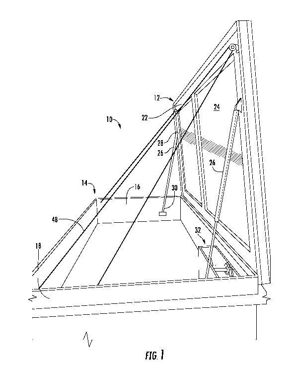
Fig. 1 shows a side, perspective view of a skylight unit 10. The unit is shown
positioned in the orientation it would assume when installed in a roof ¨ where
a window
12 opens away from a casing frame 14 and upwardly with respect to the roof. As
shown, the skylight unit 10 has a substantially rectangular casing frame 14.
The casing
frame is made of panels or boards which have an inside surface 16 and an
outside
surface 18. For purposes of installation, outside surfaces 18 of the frame are
brought
into close proximity with a joist or similar support structure in the roof and
screws are
driven through the inside surface 16 of the frame 14 penetrating the same and
joining
the casing frame 14 to joists ¨ thereby forming part of the roof structure.
A window 12 is attached via hinges to the casing frame 14. The window 12 is
comprised of a structural frame or sash 22 and a glass pane 24 mounted within
the
frame 22 (the window frame/sash 22 and the glass pane 24 are collectively
referred to
as the "window" herein). At least two gas springs 26 are attached for applying
a
constant open biasing force to the inside of window 12. As shown, a first end
28 of the
gas spring is pivotably attached to the window frame and a second end 30 of
the gas
spring is pivotably attached to the inner surface 16 of the casing frame 14.
The
maximum angle at which the window opens is determined by the length and angle
of
the gas springs.
It will be understood by those of ordinary skill in the art that any of
various force
exerting arms may be used in place of or in combination with gas springs. For
example,
pneumatic, hydraulic or any such similar force exerting mechanisms that apply
constant
force such that the window is biased to open are all within the teaching of
the invention.
Moreover, it will be understood that the invention herein is not limited to a
window and
any of various roof hatches, awnings, hurricane shutters, garage doors or
similar hinged
or tracked panels or objects are within the teaching of the invention. The
term "window"
herein refers to any such hinged/tracked panel or object.
In one embodiment of the invention, and as shown in Fig. 1, the window opens
to
substantially 90 . When opening the window to a 90 angle, the window becomes
locked in place when the gas springs 26 are fully extended. That is, in one
direction
CA 02947430 2016-10-28
WO 2015/171568 PCT/US2015/029180
(opening direction) the window cannot move past the limit of the gas springs
26 and in
the reverse direction (closing direction) the window cannot overcome the
biasing force
of the gas springs 26 ¨ which maintains the window in an open position. The
only way
to close the window is to apply a force in the closing direction that is
strong enough to
overcome the opposing force exerted by the gas springs 26,
A manual control unit 32 is mounted to the inside of the casing frame 14,
which
houses the mechanical components that are used to open and close the window.
Manual control unit 32 is shown in secured to the lower right-corner of casing
frame 14
in Fig. 1. Manual control unit 32 houses the mechanical parts to control the
opening and
closing of the window 12. A cable 48 which emanates from a cable reel 44
positioned in
the control unit, is strung along the inner casing and contacts the inner
window frame 22
at each longitudinal end thereof (through a series of pulley wheels not
shown). When
the cable reel is rotated, the cable winds around the drum thereof, generating
a pulling
or closing force on the window. Continued rotation of the cable reel causes
incremental
closing of the window. Because of the constant force applied to the window,
when
rotation of the cable reel is stopped, the window will remain in place at any
point along
its 900 range of movement. Fig 1A shows a window in the process of closing. As
shown,
gas springs 26 support the window in place. Continued rotation of the cable
reel will
continue to draw the window down and ultimately close it completely.
Fig. 2 shows a top perspective view of the control unit 32. The control unit
32
shown in substantially the same orientation as it is positioned in Fig. 1.
Control unit 32
has two substantially parallel plates ¨ a right plate 34 and a left plate 36
that are joined
to together by supporting cross bars. For example, cross bar 38, fits into
corresponding
holes in respective parallel plates 34, 36 and is fastened therein.
A cable reel 44 is mounted onto the shaft of an axle 42 secured between the
parallel plates 34, 36. The cable reel 44 has a right face plate 45b a left
face plate 45a
(each face plate having an inner and outer surface) and a spooling drum 46
disposed
between respective inner surfaces of face plates 45a, 45b. Cable reel 44 is
rotatable to
wind cable 48 about the axis of spooling drum 46, which then pulls the window
downward through a series of pulley wheels that attach cable 48 to the window
12.
CA 02947430 2016-10-28
WO 2015/171568 PCT/US2015/029180
6
Force exerted by the cable reel 44 on the cable 48 by rotation thereof
overcomes the
force exerted by gas springs 26 ¨ thereby closing the window when desired by a
user.
Fig. 3 shows an enlarged front view of the cable reel 44 and other mechanical
components that are mounted about the axis of axle 42. Axle 42 is shown
protruding
from the left side of cable reel 44. Several novel mechanical parts in
accordance with
the invention are mounted along the axis of the axle 42, which will be
explained below.
When the window is in a closed position a sufficient length of cable 48 is
wound
around cable reel 44 so as to maintain pulling force against the window in
order to keep
it aligned with frame 14. In such position, the cable 48 counteracts the
opposing force of
the gas springs 26, and it maintains the window in a closed position. A reel
lock system
is utilized to lock the cable reel 44 in place with the cable 48 wound around
the drum 46
so as to prevent unintended unspooling and thereby unwanted opening of the
window.
Fig, 4 is a left side view of the cable reel 44 showing some of the novel
elements
that make up the reel locking system. As shown, a grooved wheel 50 is mounted
to the
outside surface of left face plate 45a of cable reel 44. Grooved wheel 50
communicates
with the cable reel through a series of specialized rings.
Fig. 5 is an exploded view of the specialized rings. Grooved wheel 50, the
outer
most ring, has an annular internal circumference 52 and a jagged external
circumference. The external circumference is formed of alternating jagged
projections or
teeth 54 which create pockets or grooves 56 between respective teeth 54.
Grooved
wheel 50 surrounds an intermediate ring 58. Intermediate ring 58 is a clutch
bearing that
is composed of two separate rings that each rotates in a single direction with
respect to
the other. As shown, intermediate ring 58 is a unitary ring that has three
regions ¨ an
outer ring 60, an inner ring 62 and a middle annular region 66 between the
inner and
outer rings. Middle region 66 contains a one-way movement mechanism. As shown,
inner ring 62 of intermediate ring 58 moves in the direction of arrow 64 (e.g.
counterclockwise), but it cannot move in the opposite direction because of a
ratchet
gear or similar one-way track that is disposed between outer ring 60 and inner
ring 62
(depicted as "66"). Outer ring 60 rotates in a clockwise direction (i.e. in
the direction of
arrow 65 ¨ which is opposite to the rotational direction of inner ring 64),
but it cannot
rotate in the opposite direction. As such, if outer ring 60 were locked in
place then outer
CA 02947430 2016-10-28
WO 2015/171568 PCT/US2015/029180
7
ring 60 will not be able to rotate at all and only inner ring 62 would be
allowed to rotate ¨
and, importantly, in a single direction (i.e, in the direction of arrow 64).
Intermediate ring 58 surrounds a hub bushing 68. Hub bushing 68 is a ring or
similar bushing that is connected to or integrally formed with side face plate
45a of cable
reel 44. Because hub bushing 68 is attached to cable reel 44 ¨ a barrier or
brake that
secures hub bushing 68 in place would prevent the cable reel from rotating,
whereas,
removing the brake would allow the cable reel 44 to freely rotate.
Grooved wheel 50 is attached to intermediate ring 58, for example, by way of a
connection block or key 70. Intermediate ring 58 is attached to hub bushing
68, for
example, by way of key 72. Hub bushing 68 is affixed to the side face plate
45a of cable
reel 44 and axle 42 runs through the interior circumference thereof. Rotation
of bushing
hub 68 correspondingly rotates the attached cable reel 44 ¨ and vice versa.
In operation, cable reel 44 is rotated in a counterclockwise manner (i.e. in
the
direction of arrow 74 shown in Figs 2, 3 and 4 ¨ to the left in the
orientation shown in
Fig. 4) in order to wind the cable 48 around the spooling drum 46 of cable
reel 44.
(When viewing the control unit 32 from the left side (i.e. from the plane
occupied by left
plate 36¨ as in the view shown in Fig. 4) any counterclockwise (or leftward)
rotation of
any wheel, sprocket or gear herein is defined as the "spooling direction"
hereinafter and
the clockwise (or rightward) rotation of any wheel is termed "unspooling
direction.") It
should be noted that although the disclosure describes the "spooling
direction" as
counterclockwise and vice versa, in other embodiments of the invention, the
spooling
direction may be clockwise and the unspooling direction may be
counterclockwise and
the directions described herein are exemplary only. Thus, one object of the
invention is
to employ a system that allows cable reel 44 to freely rotate in the spooling
direction
(thereby allowing a user to pull down the window), yet is unable to rotate in
the
opposite, unspooling direction (thereby preventing unintended unspooling of
the cable
reel). The above-described series of rings 50, 58, 68 are integral parts of a
reel locking
system as set forth below.
Fig. 6 shows a reel locking system that prevents the cable reel 44 from
rotating in
the unspooling direction while the window is closed or is in the process of
being closed.
In one embodiment, as part of the locking system, a pivotable lever 76 or
brake having
CA 02947430 2016-10-28
WO 2015/171568 PCT/US2015/029180
8
a first end that is mounted on an axle, button 78 or similar pivot is mounted
to left
parallel plate 36. Such connection allows lever 76 to pivot upwardly (e.g.
away from
grooved wheel 50) and downwardly (e.g. toward grooved wheel 50). A finger-like
projection 80 or similar lever segment protrudes from the bottom of lever 76.
Projection
80 is sized and shaped to insert into respective grooves 56 on grooved wheel
50. The
second end 81 of lever 76 is attached to a spring 82. Spring 82 has a first
end 84 that is
mounted to the inside surface of parallel plate 36 of the control unit 32. The
second end
of spring 82 has an attachment mechanism, such as a hook 86 for attaching to
lever 76.
Spring 82 provides constant bias against lever 76 so as to maintain projection
80
inserted in a groove 56 (as shown in Fig. 6). Projection 80 inserted in a
groove 56, is a
physical barrier to rotational movement of grooved wheel 50 ¨ thus locking
grooved
wheel 50 in place. (The term "lever" and "brake" are used interchangeably
herein.) In a
preferred embodiment, brake 76 is mounted on the inside wall of left plate 36,
but
alternative placements or arrangements are possible in different embodiments
of the
invention.
As stated, when the brake is engaged so that projection 80 of lever 76 is
inserted
into a groove 56 on wheel 50 ¨ grooved wheel 50 becomes locked in place and it
is
incapable of rotation. Wheel 50 directly surrounds and is attached to outer
ring 60 of
intermediate ring 58. As such, outer ring 60 also becomes locked in place when
ring 50
is locked. Thus, only inner ring 62 of intermediate ring 58 is capable of
rotation. That is,
although outer ring 60 is locked in place ¨ inner ring 62, which rotates in
the opposite
direction thereof is still capable of movement. Inner ring 62 directly
surrounds and is
attached to hub bushing 68. As such, hub bushing 68 and cable reel 44 attached
thereto is capable of rotation in the same direction as inner ring 62 ¨ i.e.
in the "spooling
direction" (as labeled in Fig. 4) ¨ but hub bushing 68 and cable reel 44
cannot rotate in
the counter direction ¨ i.e. in the unspooling direction (because hub bushing
68 is
attached to inner ring 62, and inner ring can only rotate in one direction
because of one-
way gear 66). That is, when the brake is engaged, the outer ring 60 of the
intermediate
ring 58 becomes locked in place (by wheel 50), leaving only the inner ring 62
to rotate in
a leftward or counterclockwise direction. The attached bushing hub 68 (and the
attached cable reel 44) is, thus, also capable of counterclockwise rotation ¨
but not
CA 02947430 2016-10-28
WO 2015/171568
PCT/US2015/029180
9
clockwise rotation. As a result, when the brake 76 is engaged, the cable reel
44 is able
to rotate in the spooling direction to reel cable in (in order to close the
window), but it is
not capable of rotating in the opposite direction (the "unspooling
direction"). This
ensures that cable reel does not accidentally or unintentionally unwind while
a user is
reeling the window closed or thereafter.
When brake 76 is released (i.e. projection 80 is withdrawn from groove 56),
the
cable reel 44 becomes free to rotate in the unspooling direction. That is,
once the brake
76 is disengaged, the grooved wheel 50 becomes unlocked and free to rotate. As
such,
when hub bushing 68 rotates in the unspooling direction (see "unspooling
arrow" in Fig.
4), hub bushing 68 causes inner ring 62 to rotate accordingly, which, in turn
causes the
intermediate ring 58 and the attached grooved wheel 50 to rotate in the
unspooling
direction as one unit. That is, once the grooved track is not locked in place,
when axle
42 and cable reel 44 rotate in an unspooling direction, hub busing 68,
intermediate ring
58 and grooved wheel 50 rotate as one unit. That is, hub bushing 68 rotates in
the
unspooling direction (see arrow in Fig. 4); thus, bushing 68 bears against
inner ring 62
of intermediate ring 58. Because the unspooling direction is the opposite of
inner ring's
62 one-way movement, inner ring 62 will bear against one-way gear 66 ¨ causing
outer
ring 60 and attached grooved wheel 50 to similarly rotate.
As will be explained in more detail below, disengaging the brake 76 causes the
window to automatically open. That is, once cable reel 44 becomes free to move
in the
unspooling direction, the force exerted by the gas springs pushes the window
open ¨
causing the cable 48 to unspool from the spooling drum 46. To close the
window, cable
reel 44 is rotated in the spooling direction and as the cable length wraps
around the
drum of cable reel 44 it pulls in the window ¨ overcoming the force of the gas
springs.
In an embodiment of the invention, a single chain or similar cable is used to,
both, open and close the window 12 by pulling the chain in alternate
directions. With
reference to Fig. 7, which is a rear view of the control unit 32, a chain 88
is shown
wrapped around a segment of pulley wheel 90. Pulley wheel 90 is mounted on and
attached to rear axle 92. Respective ends of axle 92 are anchored in
respective
apertures in parallel plates 34, 36. A rear sprocket wheel 94 also is mounted
around the
shaft of axle 92 which retains a chain 96 (the sprocket is largely obscured by
chain 96).
CA 02947430 2016-10-28
WO 2015/171568 PCT/US2015/029180
As such, the rotation of pulley wheel 90 causes corresponding rotation of rear
sprocket
wheel 94. Chain 96 extends to the front of the control unit where it is pulled
around a
front sprocket wheel 98 (as shown in Fig. 2). It will be understood by those
of ordinary
skill in the art that pulley wheel 90 may be rotated by any of various
mechanical means,
such as by any of various chains or poles that are mechanically linked to the
pulley
wheel 90.
It should be noted that chain 88 may be pulled at two different locations to
effect
different movement of the pulley wheel 90. That is, front chain length 88a
rotates the
pulley in the spooling direction (direction of arrow 89 ¨ e.g.
counterclockwise) and
pulling down on rear chain length 88b causes pulley wheel 90 to rotate in the
opposite
direction (in the direction of arrow 91 ¨ e.g. clockwise). As such, rotation
of the pulley
wheel 90 effected by a user pulling chain 88, rotates the rear sprocket wheel
94 which
also is attached to the rear axle 92. Rotation of rear sprocket wheel 94, in
turn, causes
rotation of the front sprocket wheel 98 because of the chain 96 running
between front
and back sprocket wheels. The rotation of front sprocket wheel 98 controls the
opening
and closing of the window as will be explained with reference to Fig. 3. It
will be
understood that although embodiments of the invention disclose mechanical
linkages by
way of sprocket wheels and associated chains ¨ any of various mechanical
linkages are
possible in different embodiments of the invention, all of which are within
the teaching of
the invention. For example, mechanical linkages from pulley wheel 90 to cable
reel 44
(and other linkages described herein) may be in the form of wheel gears, discs
and/or
belts.
Fig. 3 shows an enlarged view of the front axle 42 and the mechanical elements
mounted thereon. As shown, front sprocket wheel 98 is mounted around the shaft
of
front axle 42 (front sprocket wheel 98 is shown without the chain for purposes
of clarity).
A disc 100 or similar plate is mounted to the left face of front sprocket
wheel 98 and a
similar disc 102 is mounted to the outside surface of right face plate 45b of
cable reel
44. Respective discs 100, 102 are rounded protrusions having respective
annular edges
and faces 101, 103. An external surface 101 (also referred to as a "face") of
disc 100
faces an external surface 103 (also referred to as a "face") of disc 102. The
respective
external surfaces 101, 103 are substantially parallel to one another and they
each rotate
CA 02947430 2016-10-28
WO 2015/171568 PCT/US2015/029180
11
with respective rotation of the sprocket wheel 98 and cable reel 44. Disc 100
has at
least one nub or similar projection 104 extending from the external surface
101 thereof,
and disc 102 has a similar nub or projection 106 extending from its external
surface
103. Projection 104 has a flat surface 108 which is a contact surface and
projection 106
has a similar flat contact surface 110. The discs 100 and 102 are oriented in
a position
in which respective contact surfaces 108, 110 face one another, and they are
in such
proximity where the respective contact surfaces 108, 110 share the same
rotational
trajectory. In one embodiment (best shown in Figs 9-12), three separate
projections
extending from face 101 contact three corresponding projections 106 on face
103.
When front sprocket wheel 98 is rotated in the spooling direction (direction
of
arrow 74a) attached disc 100 correspondingly moves in the spooling direction.
Because
contact surfaces 108, 110 face each other and they occupy the same rotational
plane ¨
contact surface 108 of disc 100 contacts contact surface 110 of disc 102 when
disc 100
is rotated and it thereby moves disc 102 and, consequently, the attached cable
reel 44
in the spooling direction. As such, in order to close the window, a user pulls
down on
front chain length 88a of chain 88 to cause rear sprocket wheel 94, and in
turn, front
sprocket wheel 98 to rotate in the spooling direction. Front sprocket wheel
98, in turn,
causes cable reel 44 to rotate through mating discs 100, 102. As shown, a
spring 105
contacts the right side of sprocket wheel 98 and biases sprocket wheel 98
toward cable
reel 44 (i.e, leftward in the orientation shown). This maintains sprocket
wheel 98 in
contact with cable reel 44 during spooling of cable 48.
In order to close the window, a user pulls chain length 88a until sufficient
length
of cable 48 is wound around the cable reel 44 to pull the window closed. It
should be
noted that a user may incrementally close the window. As described, because
the brake
76 is engaged during closing of the window ¨ at any increment at which a user
stops
closing the window, it will be secured in place because unspooling is
prevented by the
brake.
Once the window is closed, the brake 76 must be disengaged in order to open
the window (as described above). To that end, the same chain 88 is used to
open the
window through associated linkages described below.
CA 02947430 2016-10-28
WO 2015/171568 PCT/US2015/029180
12
With reference to Fig. 7, when rear chain length 88b is pulled downward, the
associated pulley wheel 90 rotates in the direction counter to the spooling
direction (in
the direction of arrow 91). As such, rear sprocket wheel 94 and front sprocket
wheel 98
similarly rotate in the unspooling direction. When front sprocket wheel 98 is
rotated in
the unspooling (in the direction of arrow 74b in Fig 3), front sprocket 98
moves laterally
in the direction away from cable reel 44 and toward right parallel plate 34.
Such lateral
movement is achieved as follows (with reference to Figs. 8-12). It should be
noted that
first sprocket wheel
Fig. 8 shows a front view of axle 42. As shown axle 42 has a first shaft
section 43
and a second section 47 of a larger circumference than that of shaft 43. Cable
reel 44 is
mounted on shaft section 43. Sprocket wheel 98 is mounted to disc 100 ¨ such
that
sprocket wheel 98 moves laterally when disc 100 moves laterally.
As shown, a helical groove 112 is notched into second section 47 of axle 42.
Helical groove 112 is a curved notch-out in axle section 47 that opens just to
the right
(in the orientation shown) of shaft section 43. Disc 100 is mounted on shaft
section 47
through specialized posts and riders that project into and ride in helical
groove 112 to
achieve lateral movement of disc 100 and thereby, sprocket wheel 98. It should
be
noted that rear sprocket wheel 94, secondary front sprocket wheel 116 and
elevated
sprocket wheel 120 are fixed around an axle or pivot such that they are each
capable of
rotation about an axis ¨ but they are not capable in a lateral direction.
Front sprocket
wheel 98, however, is not fixed around axle 42, but rather it is attached to
disc 100. Disc
100, is mounted around a shaft section of axle 42, but not affixed thereto. As
such, disc
100 and sprocket wheel 98 can move laterally in space ¨ in addition to
rotating about an
axis.
Fig. 9 shows a left side view of disc 100 attached to sprocket wheel 98 having
pins or riders 142 projecting into helical groove 112. When sprocket wheel 98
is rotated
in the unspooling direction, the riders 142 ride into the helical groove 112
causing the
disc 100 and sprocket wheel 98 to move laterally away from cable reel 44. This
causes
disc 100 to separate from disc 102 such that respective projections 104 and
106 cannot
contact one another ¨ effectively disconnecting sprocket wheel 98 from cable
reel 44.
CA 02947430 2016-10-28
WO 2015/171568 PCT/US2015/029180
13
Sprocket wheel 98 moves laterally (through continued pulling of chain 88 in
the direction
of arrow 91 in Fig. 7) until the riders 142 reach the end wall 114 of the
helical groove.
Fig. 10 shows an exploded view of disc 100, attached sprocket wheel 98, and
mechanical connections for supporting and maintaining posts and riders that
project into
the lumen of disc 100. As shown, disc 100 is substantially donut-shaped having
an
annular edge or outside wall 130 and a lumen 131 defined by inner wall 132. A
plurality
of holes 134 are made in the outer wall 130 which extend to inner wall 132 ¨
thereby
creating respective channels from the outside wall 130 to the inside lumen 131
of disc
100. A top segment of holes 134 (i.e. segment closest to outer wall 130) is
threaded so
as to engage with a screw or such similar device.
As shown, a pin or post 136 is inserted into channel 134. Post 136 is
maintained
within channels 134, but a bottom segment thereof extends into lumen 131. A
spring
138 is inserted atop of post 136, and a threaded screw 140 or similar cap is
inserted
atop of spring 138. Screw 140 is screwed into channel 134, and it bears
against spring
138, which in turn bears against post 136. As such, post 136 remains biased
into the
lumen 131 of disc 100. Collars 142 (also referred to as "riders") are mounted
to the
terminal ends of posts 136 which extend into the lumen 131 of disc 100.
Collars 142 are
generally cylindrical elements that are oriented substantially orthogonally to
posts 136.
Collars 142, which surround and capture the terminal ends of posts 136 are
sized and
shaped to insert into helical grooves 112. Rounded outer walls of riders 142
are sized
and shaped to ride along side walls 113 of helical grooves. In an embodiment
of the
invention, a band 141 is installed surrounding the annular edge of disc 100 to
ensure
that screws 140 remain in channels 134.
Disc 100 is mounted on shaft section 47 with riders 142 inserting into helical
grooves 112. Fig. 11 shows a left side view of disc 100 with riders 142
positioned at a
proximal position within helical grooves 112. At such proximal position, disc
100 is
positioned in close enough proximity to disc 102 such that projections 104
extending
therefrom contact corresponding projections 106 on disc 102 so that rotation
of disc 100
(in the spooling direction) causes corresponding rotation of cable reel 44
(best shown in
Fig. 3).
CA 02947430 2016-10-28
WO 2015/171568 PCT/US2015/029180
14
Conversely, rotation of sprocket wheel 98 in the unspooling direction (in
direction
74b of Fig. 3), causes lateral movement of disc 100 and sprocket wheel 98 such
that
disc 100 of sprocket wheel 98 becomes separated from disc 102 of cable reel
44. That
is, when sprocket wheel 98 is rotated in the unspooling direction, riders 142
ride into
helical grooves 112 and continue riding along helical grooves 112 as sprocket
wheel 98
continues rotating in the unspooling direction. Fig. 12 shows disc 100 of
sprocket wheel
98 at a distal end of helical grooves 112. When the riders 142 reach the end
wall 114 of
the helical grooves 112, end wall 114 serves as a physical barrier preventing
further
movement of disc 100 and sprocket wheel 98 in the lateral direction. Continued
rotational motion in the unspooling direction (through continued pulling of
chain 88 in the
direction of arrow 91 in Fig. 7) causes the riders 142 (supported by posts
136) to bear
against the end wall 114 of helical grooves 112 causing axle 42 to rotate in
the
unspooling direction thereby unlocking cable reel 44 to unspool cable 48 as
will be
described below. After disc 100 reaches terminal end of helical groove 112, it
may be
rotated in a first direction to move back to the proximal end thereof. As
such, disc 100
and sprocket wheel 98 are movable in two directions within a lateral plane, in
addition to
being rotatable about an axis.
Referring to Figs. 3 and 8, a secondary front sprocket 116 also is mounted
around the shaft of front axle 42. As such, when riders 142 reach the end wall
114 of
helical grooves 112 and cause axle 42 to rotate in the unspooling direction
(through
continued pulling of chain 88 in the direction of arrow 91 in Fig. 7) ¨
secondary front
sprocket 116, thus, also rotates in the unspooling direction.
As shown in Fig. 2, secondary front sprocket wheel 116 retains a chain 118,
which connects secondary front sprocket wheel 116 to an elevated sprocket
wheel 120.
Rotation in the unspooling direction of secondary front sprocket wheel 116
causes
corresponding rotation of elevated sprocket wheel 120. Elevated sprocket wheel
120
surrounds an inner one-way gear or one-way clutch bearing 148. A cross bar 124
is
attached to the center of the clutch bearing 148 and extends therefrom. The
second end
of cross bar 124 is attached to a chain 128. As shown, the first end of chain
128 is
attached to cross bar 124 and the second end of chain 128 is attached to the
second
end of brake 76. As such when secondary front sprocket wheel 116 is rotated in
the
CA 02947430 2016-10-28
WO 2015/171568 PCT/US2015/029180
unspooling direction, attached elevated sprocket wheel 120 correspondingly
rotates in
the unspooling direction (in the direction of arrow 121). Attached cross bar
124 similarly
rotates in the unspooling direction, and in turn, chain 128 slightly wraps
around the shaft
of cross bar 124 causing the chain to be somewhat raised (with respect to the
floor).
Second end of chain 128 thereby lifts brake 76 off of grooved wheel 50 ¨
freeing cable
reel 44 to rotate in the unspooling direction. As described above, this causes
the
window to automatically open ¨ as the force exerted by the gas springs 26 are
no longer
countered by the locked cable reel 44.
It should be noted that when secondary front sprocket 116 rotates in the
spooling
direction, then elevated sprocket wheel 120 correspondingly rotates in the
spooling
direction ¨ but the attached cross bar 124 does not rotate on account of its
attachment
to one-way gear. However, when elevated sprocket wheel 120 rotates in the
unspooling
direction, cross bar 124 is correspondingly rotated to as described in more
detail below.
Fig. 13 shows an exploded view of elevated sprocket wheel 120 and associated
one-way clutch bearing 148. As shown, sprocket wheel 120 has an internal ring
146
which surrounds a one-way gear 148. One-way gear 148 is a unitary ring that
has three
regions ¨ an outer ring 150, an inner ring 152 and a middle region 154 between
the
inner and outer rings. Middle region 154 contains a one-way movement
mechanism. As
shown, outer ring 150 moves in one direction only (e.g. counterclockwise as
depicted by
arrow 158), but it cannot move in the opposite direction because of a ratchet
gear or
similar one-way track that is disposed between outer ring 150 and inner ring
152. Inner
ring 152 rotates in a clockwise direction (i.e. in the direction of arrow 158)
but it cannot
rotate in the opposite direction. Internal ring 146 of sprocket wheel 120 is
attached to
one-way gear 148 by key 160. A bottom plate 121 and a cover plate 122
encapsulate
the one-way bearing 148.
Fig. 14 shows a side view of elevated sprocket wheel 112 and one-way gear 148
attached to the inner circumference thereof. As shown, when sprocket wheel 112
rotates in the spooling direction (e.g. in the direction of arrow 156), outer
ring 150
rotates in the same direction because its direction of movement is in the
spooling
direction; however, inner ring 158 does not rotate. Conversely, when sprocket
wheel
112 rotates in the unspooling direction (e.g. in the direction of arrow 158),
attached
CA 02947430 2016-10-28
WO 2015/171568 PCT/US2015/029180
16
outer ring 150 bears against middle region 154 and middle region 154 bears
against
inner ring 158 thereby causing the same to rotate in its direction of movement
(e.g.
clockwise as depicted by arrow 158).
The shaft of cross bar 124 inserts into the lumen of inner ring 152 and is
attached
thereto by way of key 161 (cross bar 124 not shown in Figs 14 and 16). As
such,
rotation of inner ring 152 effectuates corresponding rotation of cross bar
124. Thus, as
described, in order to open the window, a user will pull on chain length 88b
ultimately
achieve unspooling rotation of elevated sprocket wheel 112, inner ring 152 and
attached
cross bar 124. As described, cross bar 124 rotates so as to raise chain 128
and thereby
free brake 76 (overcoming spring 82 shown in Fig. 6). Once brake 76 is removed
from
grooved wheel 50 ¨ there is no longer a lock on cable reel 44. Thus, the gas
springs 26
force the window upward and open.
Gas springs 26 apply a strong biasing force against the window 12, such that
when counterforce is removed ¨ the window is rapidly forced upwardly with a
great deal
of force and speed. In an embodiment of the invention, a damper system is
employed to
reduce the speed at which the window rises.
Fig. 15 shows an exploded view of a damper system 162 according to an
embodiment of the invention. The damper system 162 is a ring-shaped band that
surrounds disc 102 attached to cable reel 44. The band applies friction to
disc 102 to
slow the speed at which cable reel 44 unspools ¨ thereby slowing the speed of
the
opening window 12.
Damper 162 is a loop having an inner belt 164 that is made of leather, Teflon,
plastic or such similar soft and flexible, yet resilient material and an outer
band 166 that
surrounds belt 164. Outer band 166 is a thin strip, preferably made of a
metallic material
such as aluminum, stainless steel or the like and is sized and shaped to
tightly conform
to the outside perimeter of belt 164. Terminal ends of outer band 166 and
inner belt 164
flange outwardly forming flanged ends 168a, 168b and 170a, 170b (of belt 164
and
band 166, respectively). Each flanged end has a hole 172 or similar aperture.
Outer band 166 is placed around belt 164 such that flanged ends and holes in
flanged ends are aligned. A bolt 174 having a hole 176 at its terminal end is
used to
attach damper 164 to control unit 32. As shown, terminal end of bolt 174 is
positioned
CA 02947430 2016-10-28
WO 2015/171568 PCT/US2015/029180
17
between flanged ends 168a, 168b of belt 164 with hole 176 aligning with holes
on
flanged ends. A screw 178 is inserted to maintain the damper in a closed loop
and to
attach the same to bolt 174. Screw is inserted through the hole in flanged end
170a of
band 166, through the hole in flanged end 168a of belt 164, through the hole
176 of bolt
174, through the flanged end 168b of belt 164, and finally through the hole on
flanged
end 170b of band 166. A nut 179 or similar fastener is attached or screwed on
to
terminal end of screw 178. As stated, screw 178, both, fastens the loop
(created by
band 166 and belt 164) closed and also attaches the loop to bolt 174.
Bolt 174 has a threaded end 177 that mates with a nut 180 or similar fastener.
A
spring 182 is inserted around a longitudinal section of bolt 174. As shown, a
bottom cap
184 is inserted onto bolt 174 which contacts the bottom of spring 182 and
prevents
spring 182 from moving past cap 184. An upper cap 186 is inserted just above
of spring
182 which contacts the top of spring 182 when nut 180 is tightened.
Fig. 16 shows damper system 164 attached to control unit 32 according to an
embodiment of the invention. As shown, the loop of damper unit 164 surrounds
disc 102
of pulley reel 44 with inner belt 164 contacting the annular edge of disc 102.
Bolt 174 is
inserted through a channel in cross bar 188 with terminal threaded end 177
projecting
upwardly from cross bar 188.
In use, damper 164 is tightened and/or adjusted in the following manner. Nut
180
is rotated so that it moves down the shaft of bolt 174 until it contacts upper
cap 186.
Upper cap 186 bears against spring 182, thereby causing spring 182 to exert
tension on
cap 186 and nut 180. Such tension against cap 186 and nut 180 causes bolt 174
to be
incrementally moved upward. Such incremental movement of bolt 174 causes a
tensioning force on damper 162. Continued rotation of nut 180 causes bolt 174
keep
traveling upwardly thereby applying greater tensioning force on attached
damper 162. A
user or factory can set the bolt to a specified level of tension to ensure
controlled
opening of window 12.
Another aspect of the invention is an improved apparatus and method for
reeling
cable or similar cord. Cable often spools around a cable reel in a haphazard
fashion,
possibly causing tangling or snarling of the cable. An embodiment of the
invention
CA 02947430 2016-10-28
WO 2015/171568 PCT/US2015/029180
18
prevents such tangling by employing a novel cable reel drum that is designed
to guide
cable to spool in a controlled and organized manner.
Fig. 17 shows an embodiment of a novel cable reel 44 according to an
embodiment of the invention. Fig. 17 shows a cable reel 44 with an aperture
190 from
which a cable emanates (cable not shown). A curved wall or ramp 192 begins at
the
point at which cable is attached to reel 44. Ramp 192 gradually slopes toward
one side
of the reel (to the right in the orientation shown in Fig. 17). That is, the
distance between
wall of ramp 192 and left side face plate 45a increases as ramp 192 extends
around the
drum 46 of pulley wheel 44. Ramp 192 guides cable that is being spooled to
move
rightward (in the orientation shown) as it winds around the drum 46. Ramp 192,
thus,
divides drum 46 into two sections: an upper section 193 and a lower section
195. A step
194 down, separates upper section 193 from lower section 195. Step 194 extends
roughly 900 down from upper section 193. Preferably the height 196 of step 194
is
substantially the same as the diameter of cable that is to be reeled. As such,
when
cable is reeled using the inventive cable reel 44, cable is urged to the right
by ramp 192
and it continues spooling into lower drum section 195 until it reaches right
face plate
45b.
Fig. 17 shows a schematic cross-sectional view of a first row of cable 198
wound
around lower drum section 195. Once cable reaches side face plate 45b, it will
begin
spooling in the other direction (e.g. to the left). Because, the height of
step 194 is
substantially the same as the cable diameter, once a first layer 198 of cable
is laid down
between step 194 and face plate 45b, there is a continues layer upon which a
second
layer of cable may wind. Fig. 17 schematically shows a cross-sectional view of
a second
layer 200 of cable wound atop a substantially continuous surface formed by
first layer
198 and second upper section 193. This process continues until all cable is
wound
around cable reel 44.
Also shown in Fig. 17 is a lip 202 that extends around and orthogonally to the
annular edge of disc 102. The height of lip 202 is substantially equal to or
somewhat
greater than the combined thickness of band 166 and belt 164 of damper system
162.
Lip 202, thus, acts as a physical barrier preventing lateral movement or
slippage of
damper system 162.
=
CA 02947430 2016-10-28
WO 2015/171568
PCT/US2015/029180
19
While the present invention has been described with respect to an exemplary
embodiments, it will be appreciated that many modifications and variations may
be
made without departing from the true spirit and scope of the invention. It is,
therefore,
the intent of the present application to cover all such modifications and
variations which
fall within the true spirit and scope of the invention.