Note: Descriptions are shown in the official language in which they were submitted.
CA 02947906 2016-11-03
WO 2015/168790 PCT/CA2015/050396
SEAT SUSPENSION SYSTEM, APPARATUS, AND METHOD OF USING SAME
CROSS-REFERENCE TO RELATED APPLICATIONS
100011 This application is related and claims priority to US Provisional
Patent Application Serial
No. 61/989,406 filed May 6, 2014, which is hereby incorporated herein by
reference in its entirety.
TECHNICAL FIELD
[0002] The present disclosure technically relates to shock absorption systems
and apparatus. More
specifically, the present disclosure technically relates to isolator systems
and apparatus for use in
shock mitigation in vehicle applications such as vehicle seat shock absorption
systems and
apparatus for marine, air, land and space vehicle seats. Even more
specifically, the present
disclosure technically relates to hydro-pneumatic cylinder isolator systems
and apparatus having
multiple pneumatic reservoir volumes for shock absorption and include isolator
system
embodiments having multiple pneumatic reservoir volumes which may be
selectively engaged at
optimal control switching points to provide similar force mitigation for a
variety of different
payloads.
BACKGROUND
[0003] Many related art technologies are currently utilized for vehicle
suspension in general.
These related art technologies usually involve either pneumatic or hydro
pneumatic suspension
with passive or semi-active control over the suspension stiffness and damping.
Other related are
systems include supplemental accumulators or dampers.
[0004] For instance, Deo and Suh in PNEUMATIC SUSPENSION SYSTEM WITH
INDEPENDENT CONTROL OF DAMPING, STIFFNESS AND RIDE-HEIGHT (icad-2006022,
4TH International Conference on Axiomatic Design, Firenze June 13-16, 2006)
(hereinafter "Deo")
disclose a variable air volume pneumatic system with variable stiffness and
ride height achieved
by pumping air in and out across multiple volumes.
100051 Also, U.S Patent No. 5,141,244 to Clotault et al. of Automobiles
Peugeot (hereinafter
"Peugeot"), discloses a hydro pneumatic suspension system for vehicles with an
accumulator and
damper for each vehicle wheel, and supplemental hydro pneumatic accumulators
for each axle for
1
CA 02947906 2016-11-03
WO 2015/168790 PCT/CA2015/050396
firmer suspension when the supplemental units are switched out and softer
suspension when they
are switched in.
[0006] In addition, US Patent No. 4,664,410 Richard to Automobiles Peugeot and
Citroen
(hereinafter "Citroen") discloses an oleo pneumatic suspension system for
motor vehicles with a
suspension cylinder and hydraulic accumulator and damper for each wheel.
[0007] Finally, Giliomee, Els and van Niekerk in Anelastic Model of a Twin
Accumulator Hydro-
pneumatic Suspension System (R&D Journal, 2005, 21 (2) incorporated in the SA
Mechanical
Engineer) provide a mathematical model for a semi-active twin suspension
system with all valves
open to evaluate performance criteria.
[0008] The related art does not provide a technique for providing a simple
passive or semi-active
control system for suspension systems having multiple reservoirs controllable
in adverse
environments, such as high speed marine, land, or air vehicles operating in
variable weather and
lighting. One company, Shockwave Seats, discloses a static modification to
reduce canister volume
by adding filler "pills" into the air chamber as a one-time "set-up" to suit
the vessel, seating
location in the vessel, and anticipated operating conditions and user
preference but does not
provide for external control of the suspension system after installation or
during use.
[0009] While these background examples may in some cases relate to twin
suspension systems
for motor vehicles, they fail to disclose a system or an apparatus adapted for
use with a single
suspended component such as a seat, nor for a seat in a marine vehicle, and
particularly not for a
single native hydro-pneumatic isolator in a seat for a marine vehicle, that is
capable of optimally
controlling a switching point for addition to the system of a second or
plurality of supplemental
cylinders or reservoirs to achieve consistent shock mitigation for a variety
of payloads. Related
art twin suspension technology has not been known to be adapted for use with
high speed marine
vehicles or even for single seat isolator systems. As such, a long-felt need
has been experienced
in the related art for a system and apparatus that overcomes the inability to
provide consistent
shock mitigation across multiple payloads with a simple, adverse environment
resistant multiple
suspension passive system on a marine vehicle seat.
[0010] Pressure and damping adjustments may be used to accommodate variances
in payload
weight and environmental conditions. Pressure and/or damping adjustments
typically offer
negligible performance advantages when compared to volume adjustments.
Conventional semi-
active damping-controlled isolators are typically expensive to manufacture and
have typically
2
CA 02947906 2016-11-03
WO 2015/168790 PCT/CA2015/050396
failed to provide the desired increased performance of additional volume
reservoir systems. There
is a need, therefore, to meet the demands of use on watercraft where
simplicity of operation (so as
to be usable in adverse conditions day or night) and resistance to extreme
marine environmental
conditions are desired.
SUMMARY
100111 In addressing many of the problems experienced in the related art, such
as expensive
manufacture, complex operation leading to operator errors in selecting
settings, inefficient fluid
flow from reservoirs and through connecting passageways, the present
disclosure generally
involves additional volume reservoirs with: optimized passageway size/shape
(restrictions
minimize effectiveness of additional volume reservoirs); optimized reservoir
volume(s), and
control switching points; and simple and easily understood and operated
adjustment controls. The
presently disclosed isolator systems and apparati are beneficial for use with
land vehicles, aircraft,
spacecraft, and watercraft, such as for suspending single component loads such
as seats in such
vehicles, aircraft, spacecraft and watercraft. In one embodiment, systems and
methods according
to the present disclosure may desirably be particularly beneficial for shock
mitigation in high speed
marine vehicle seats. In one such exemplary embodiment, many types of vehicles
(including but
not limited to land, water and air vehicles) may desirably benefit from an
installation or a retrofit
with isolator systems such as hydro-pneumatic cylinder isolator systems
according to the present
disclosure so as to desirably provide for mitigation of shock forces
transferred to seat occupants
or users particularly during use in adverse conditions.
[0012] In one embodiment according to the present disclosure, a suspension
system comprises
an isolator cylinder such as a hydro-pneumatic isolator cylinder; a primary
reservoir comprising
a primary reservoir volume, a secondary reservoir comprising a secondary
reservoir volume, an
end cap attached to the primary reservoir of the isolator cylinder and
comprising a primary duct
opening fluidly connected to a primary duct, a primary duct connecting the
primary reservoir to
the secondary reservoir, and a manifold through which the primary duct passes,
wherein at least
one of the primary duct opening and the primary duct are configured to control
a flow rate of a
fluid through the primary duct between the primary and secondary reservoirs.
In one such
embodiment, the primary duct comprises a cross sectional area and a length
such that a fluid
flowing through the primary duct between the primary and secondary reservoirs
does not
3
CA 02947906 2016-11-03
WO 2015/168790 PCT/CA2015/050396
contribute to a damping of the isolator cylinder. In a further embodiment, the
primary duct
comprises a diameter D and a length L such that a ratio of L/D is less than
about 24. In yet
another embodiment, the primary reservoir additionally comprises a primary
piston having a
cross sectional area Apiston, and the primary duct comprises a cross sectional
area Amid and a
Length L, such that Amiia > Ci A0011 Vmax; wherein
Aduct is the cross sectional area of the primary duct in square inches,
Apiston
is the cross sectional area of the primary piston in square inches,
V. is a maximum velocity of the primary piston in inches/second, and
CI is a constant substantially equal to 3.5 x 10 [s/in].
[0013] In another embodiment, the suspension system described above may
additionally comprise
a valve for controlling a flow rate of a fluid through the duct; and a control
system for operating
the valve for controlling the flow rate of the fluid between the primary and
secondary reservoirs.
In a further embodiment, the valve may desirably control a flow rate of the
fluid between the
primary and secondary reservoirs such as by opening and closing the primary
duct, or at least
partially opening or closing the primary duct, or further by controllably
varying or limiting the rate
of fluid flow between the primary and secondary reservoirs between at least
upper and lower fluid
flow rate limits, for example. In yet a further embodiment, the suspension
system may additionally
comprise a control system for controlling a flow rate of the fluid between the
primary and
secondary reservoirs. In one exemplary embodiment, the fluid may comprise at
least one of air,
nitrogen or another suitable compressible fluid. In another exemplary
embodiment the primary
reservoir may desirably be disposed entirely within or at least partially
within the cylinder, such
as within a hydro-pneumatic isolator cylinder, for example. In one such
embodiment, the isolator
may comprise a native hydro-pneumatic cylinder isolator comprising a primary
reservoir disposed
within the cylinder, such as a commercially available single cylinder isolator
such as the Fox Float
3TM hydro-pneumatic cylinder isolator available from Fox Manufacturing of
Scotts Valley,
California, U.S.A., for example.
[0014] Additionally, in one embodiment, the suspension system may be used with
an occupant or
user seat in at least one of a marine, land or air vehicle to provide for
mitigation of shock or force
transmitted to the occupant of the seat. In one such embodiment, at least one
of the primary duct
opening and the primary duct of the suspension system may be configured to
control a flow rate
4
CA 02947906 2016-11-03
WO 2015/168790 PCT/CA2015/050396
of a fluid through the primary duct between the primary and secondary
reservoirs to control the
suspension response of the suspension system and to desirably provide for
improved mitigation of
shock or force transmitted to the seat occupant. In another embodiment, the
suspension system
may comprise a valve for controlling a flow rate of a fluid through the duct;
and a control system
for operating the valve for controlling the fl ow rate of the fluid between
the primary and secondary
reservoirs. In a further embodiment, the control system may include a sensor
for measuring an
external force due to a weight of the seat in an occupied state, a
microprocessor or microcontroller
for storing a predetermined force due to a weight of the seat in an unoccupied
state and an external
force due to a weight of the seat in an occupied state and for determining the
weight of an occupant
of the seat (such as by comparing the predetermined force due to a weight of
the seat in an
unoccupied state with the external force due to a weight of the seat in an
occupied state), and for
controlling the control system, such as a controller for adjusting the valve
based on the weight of
an occupant of the seat (such as by determining a differential between the
external force due to the
weight of the seat in an occupied state and the predetermined force due to the
weight of the seat in
an unoccupied state and adjusting the valve based on the weight differential).
[0015] In one embodiment, the control system may also comprise an actuator for
operating the
valve. In a further such embodiment, the actuator may comprise a switch, which
may optionally
be manually controlled to operate the valve. In another embodiment, the
actuator may comprise a
switch and may be automatically controlled to automatically operate the valve,
and may also
optionally be manually controllable such as for a manual override of the valve
operation. In a
further embodiment, the control system may also comprise a power source for
delivering power to
the control system such as for powering at least one of the microprocessor or
microcontroller and
an actuator.
[0016] In another embodiment of the present invention, the suspension system
comprises an
isolator cylinder such as a hydro-pneumatic isolator cylinder, a primary
reservoir comprising a
primary reservoir volume, an end cap attached to the primary reservoir of the
isolator cylinder and
comprising a primary duct opening fluidly connected to a plurality of ducts,
and a plurality of
secondary reservoirs, each of the plurality of secondary reservoirs comprising
a secondary
reservoir volume, a plurality of ducts connecting the primary reservoir to the
plurality of secondary
reservoirs, each of the plurality of ducts comprising a duct cross sectional
area, and a duct length,
a plurality of valves for controlling a flow rate of a fluid through the each
of the plurality of ducts,
5
CA 02947906 2016-11-03
WO 2015/168790 PCT/CA2015/050396
and at least one manifold through which at least one duct connected to the
primary reservoir passes.
In another embodiment, the suspension system additionally comprises a control
system for
controlling a flow rate of the fluid between at least one of the plurality of
secondary reservoirs and
the primary reservoir.
100171 In a further aspect according to an embodiment of the present
invention, a method for
absorbing shock transferred to a seat in a vehicle is disclosed. In one such
embodiment, the method
may be implemented to desirably improve the performance of the suspension
system installed in
a vehicle seat. In one such embodiment, the method comprises: providing a
suspension system
comprising an isolator cylinder such as a hydro-pneumatic isolator cylinder, a
primary reservoir
comprising a primary reservoir volume, at least one secondary reservoir
comprising a secondary
reservoir volume, at least one duct connecting the at least one secondary
reservoir to the primary
reservoir, the at least one duct comprising a duct cross sectional area and a
duct length, at least one
valve for controlling a flow rate of a fluid between the primary and at least
one secondary reservoir
through the at least one duct, and at least one manifold through which the at
least one duct passes.
In one such embodiment, the method further comprises providing a control
system for controlling
a flow rate of the fluid between the primary and the at least one secondary
reservoir; providing a
stored predetermined force due to the weight of the seat in an unoccupied
state, measuring an
external force due to a weight of the seat in an occupied state, calculating a
force differential
between the stored predetermined force and the external force, and adjusting
the delivery of a fluid
from the reservoirs to the cylinder by controlling the position of the at
least one valve in response
to the force differential between the stored predetermined force and the
external force to control
the shock mitigation response of the suspension system.
100181 In yet a further aspect according to an embodiment of the present
invention, a method for
configuring a suspension system is provided. In one such embodiment, the
method comprises:
defining a suspension load range (such as an occupant weight range for a seat
suspension
system) and a shock or input acceleration profile (such as but not limited to
at least one of
magnitude, duration or period and shape of input acceleration pulses);
selecting a suitable native
isolator comprising a primary reservoir (such as but not limited to a
commercial isolator product
and size and an isolator mounting linkage geometry if any); determining a
secondary reservoir
volume for a secondary reservoir; determining a primary duct cross-sectional
area and length for
a primary duct fluidly connecting the primary and secondary reservoirs;
determining a reservoir
6
CA 02947906 2016-11-03
WO 2015/168790 PCT/CA2015/050396
pressure such that the isolator does not bottom out or exceed a maximum
allowable stroke length
for the maximum suspension load during the most extreme or maximum
acceleration condition
of the shock acceleration profile; and determining a damping coefficient
selected to provide a
rebound time less than the period of the shock acceleration for the shock
acceleration profile. In
-- a further embodiment, the method additionally comprises determining a
switching load or weight
for a switching valve situated in the primary duct between the primary and
secondary reservoirs.
In an additional aspect according to an embodiment of the present invention,
the method for
configuring the suspension system additionally comprises providing a
suspension system, the
suspension system comprising a native isolator cylinder comprising a primary
reservoir;
-- providing the secondary reservoir comprising the secondary reservoir
volume; providing an end
cap attached to the primary reservoir of the isolator cylinder and comprising
a primary duct
opening fluidly connected to the primary duct; fluidly connecting the
secondary reservoir to the
primary reservoir by the primary duct of the cross-sectional area and length
determined; and
pressurizing the secondary reservoir to the pressure determined. In a further
such embodiment,
-- the method may additionally comprise: determining a switching load for a
switching valve
situated in the primary duct for controlling the flow of a fluid between the
primary reservoir and
the secondary reservoir; and providing a switching valve disposed in the
primary duct for
controlling a rate of flow of a fluid between the primary reservoir and the
secondary reservoir
according to the switching load. In yet a further embodiment, the method may
further comprise
-- determining a damping coefficient to provide an isolator rebound time of
between 0.2 and 0.5
seconds. In a particular embodiment, the method of configuring a suspension
system may
desirably provide for use of a maximum available range of isolator travel
while preventing
bottoming out or over-compression of the isolator over a defined range of
suspension loads. In
an exemplary embodiment directed to applications in seat suspension systems,
the defined range
-- of suspension loads may comprise a defined range of seat occupant weights,
for example.
[0019] Benefits of systems and methods according to an embodiment of the
present disclosure
include, but are not limited to, providing a passive isolator system with a
primary and at least one
secondary reservoir fluidly connected in an efficient manner by at least one
passageway or duct
comprising a selected and desirably optimal duct cross sectional area, length
and reservoir volume
-- to desirably optimize operation of the suspension system to provide shock
mitigation to a
7
CA 02947906 2016-11-03
WO 2015/168790 PCT/CA2015/050396
suspension system load such as a suspended seat occupant, across a range of
load or occupant
weights.
BRIEF DESCRIPTION OF THE DRAWINGS
[0020] The above, and other, aspects, features, and advantages of several
embodiments of the
present disclosure will be more apparent from the following Detailed
Description as presented in
conjunction with the following figures of the Drawings.
[0021] FIG. 1 is a side view of a hydro-pneumatic cylinder isolator having a
secondary reservoir
attached to the primary reservoir of the isolator by a fluid passageway, valve
and manifold in
accordance with an embodiment of the present disclosure.
100221 FIG. 2 is a perspective view of a hydro-pneumatic cylinder isolator
having a secondary
reservoir attached to the primary reservoir of the isolator by a fluid
passageway, valve and
manifold in accordance with an embodiment of the present disclosure.
[0023] FIG. 3 is a perspective view of a two (2) position (or detent) passive
isolator reservoir
volume selector system attached to a marine seat base in accordance with an
embodiment of the
present disclosure.
[0024] FIG. 4 is a rear perspective view of a shock-absorbing vehicle seat
incorporating a hydro-
pneumatic cylinder isolator having a secondary reservoir in accordance with an
embodiment of the
present disclosure.
DETAILED DESCRIPTION
[0025] The following description is not to be taken in a limiting sense, but
is made merely for the
purpose of describing the general principles of exemplary embodiments. The
scope of the
disclosure should be determined with reference to the Claims. Reference
throughout this
specification to "one embodiment," "an embodiment," or similar language means
that a particular
feature, structure, or characteristic that is described in connection with the
embodiment is included
in at least one embodiment of the present disclosure. Thus, appearances of the
phrases "in one
embodiment," "in an embodiment," and similar language throughout this
specification may, but
do not necessarily, all refer to the same embodiment.
[0026] Further, the described features, structures, or characteristics of the
present disclosure may
be combined in any suitable manner in one or more embodiments. In this
Detailed Description,
8
CA 02947906 2016-11-03
WO 2015/168790 PCT/CA2015/050396
numerous specific details are provided for a thorough understanding of
embodiments of the
disclosure. One skilled in the relevant art will recognize, however, that the
embodiments of the
present disclosure can be practiced without one or more of the specific
details, or with other
methods, components, materials, and so forth. In other instances, well-known
structures,
materials, or operations are not shown or described in detail to avoid
obscuring aspects of the
present disclosure.
[0027] In one embodiment, the present disclosure provides a seat suspension
isolator (also known
as a shock absorber), for use in seats aboard land, air, sea or space
vehicles, such as high speed
watercraft or marine vehicles for example, and desirably provides for improved
shock mitigating
performance as compared to conventional isolator designs of both the passive
and semi-active
(such as computer or otherwise electronically or electro-mechanically
controlled), variety. In one
such embodiment, a seat suspension isolator according to the present invention
may desirably
provide improvements in shock mitigation performance across the widest range
of seat/occupant
weights or other suspension system payloads and environmental conditions. In
one embodiment
adapted for use in high speed marine vehicle (boat) seat suspension systems, a
typical design range
for seat occupant/operator or user weight is 100-300lb; and a typical design
range for vehicle deck
accelerations (i.e. input shock or impact accelerations) range from 0-16g. In
another embodiment,
a suspension system may be applied to use in seat suspension systems in other
types of vehicles or
seats in various locations subject to movement, shock or impact of vehicular
or other types. In an
alternative embodiment, suspension systems according to aspects of the present
invention may
also be adapted for use in shock mitigation suspension of other suspended
loads outside of seats,
and may typically be applied to mitigate shock for suspension of any suitable
single-point
suspended load adapted for attachment to an isolator suspension system
according to an
embodiment of the invention. In one embodiment, a suspension system according
to an aspect of
the present invention comprises a native isolator comprising a primary fluid
reservoir disposed
entirely or at least partially within an isolator cylinder, and further
comprises at least one secondary
fluid reservoir (where the fluid may comprise air, nitrogen or another
suitable compressible fluid)
connected to the primary fluid reservoir of the isolator cylinder by a primary
fluid duct, where the
secondary fluid reservoir effectively alters the volume of the primary
reservoir. In one such
embodiment, the isolator cylinder may comprise a suitable hydro-pneumatic
isolator cylinder, such
as a native hydro-pneumatic cylinder isolator comprising a primary reservoir
disposed within the
9
CA 02947906 2016-11-03
WO 2015/168790 PCT/CA2015/050396
cylinder, such as a commercially available single cylinder isolator such as
the Fox Float 3TM hydro-
pneumatic cylinder isolator available from Fox Manufacturing of Scotts Valley,
California,
U.S.A., for example.
[0028] In one embodiment, a suspension system according to an aspect of the
present invention
may desirably provide for improved performance of the isolator by providing at
least one
specifically sized, additional volume secondary fluid reservoir (in various
embodiments) in
addition to the primary reservoir of the isolator, which is specifically tuned
or configured to the
shock inducing environment or input acceleration profile experienced in a
desired shock mitigation
application, such as for example for a seat suspension system aboard a high
speed watercraft, or
land vehicle or other specific desired application with a corresponding
specific input acceleration
profile. In one embodiment, the secondary fluid reservoir may be fluidly
connected to the primary
reservoir by a primary fluid duct which is fluidly connected to a primary duct
opening in an end
cap attached to the primary reservoir of the isolator cylinder. In another
embodiment, the
suspension system may also comprise a fluid flow control valve, and the rate
of fluid flow between
the primary and secondary reservoirs may be controlled by at least one the
cross sectional area and
length of the primary duct or duct opening, or by controlling the fluid flow
control valve. In one
embodiment, a fluid flow control valve may be manually adjusted (such as by a
user) or controlled
mechanically or electronically, for instance by a PLC, sensor input or vehicle
or other installation
specific parameters. In one embodiment providing for mechanical and/or
electrical/electronic
control of the fluid flow rate between primary and secondary reservoirs, a
manual override such
as by operation of a manual selector switch for example may be provided to
provide manual control
over the fluid flow rate, such as by providing manual control of the fluid
flow control valve by a
manual switch or lever, for example. In a particular embodiment, an accessory
end cap may be
provided to facilitate attachment and fluid connection of at least one
secondary fluid reservoir and
its primary duct or fluid passageway and fluid flow control valve to a known
or commercially
available native isolator product which comprises a primary fluid reservoir
therein, such as a
suitable hydro-pneumatic cylinder isolator. In one such embodiment, a suitable
commercially
available hydro-pneumatic cylinder isolator may be implemented as the native
isolator, such as a
Fox Float 3TM 5.25 inch or 10 inch hydro-pneumatic cylinder isolator available
from Fox
Manufacturing of Scotts Valley, California, U.S.A., for example.
CA 02947906 2016-11-03
WO 2015/168790 PCT/CA2015/050396
10029] In one embodiment of the present invention, an important aspect of the
improved isolator
design and function is the selection of the secondary reservoir volume. In one
such embodiment,
the cross sectional area, length and path of the primary duct or fluid
passageway between the
primary reservoir of an isolator cylinder and the secondary reservoir may
desirably be selected
such that the secondary reservoir volume achieves the highest or most improved
shock mitigation
performance across the range of anticipated suspension loads, or seat occupant
weights for a
particular application of the suspension system. In one such embodiment, the
secondary reservoir
volume may be selected such that a marginal increase in the selected secondary
reservoir volume
desirably only marginally decreases the natural frequency of local
oscillations in the isolator with
combined primary and secondary reservoir volumes when considered at an
equilibrium point at
approximately 85% of the compression range of the isolator, for example.
[0030] In one such embodiment, the secondary reservoir volume may be selected
based on the
natural frequency of local oscillations at any desired suspension load or seat
occupant weight value
for a desired application. In an exemplary embodiment where the secondary
reservoir volume is
desired to be openly fluidly connected to the primary reservoir when the
lowest suspension load
or occupant weight is set, the secondary reservoir volume may desirably be
selected based on the
natural frequency of local oscillations at the lowest suspension load or
occupant weight of the
design range. An exemplary relation between the frequency of local
oscillations considered at
85% of the compression range and the secondary reservoir volume (expressed as
a value of
secondary reservoir volume/primary reservoir volume of the isolator) of an
exemplary isolator
comprising primary and secondary reservoirs at a range of suspension load or
occupant weight
values which may be used to select a desired secondary reservoir volume
according to an
exemplary embodiment of the present invention is shown below as Chart 1.
11
CA 02947906 2016-11-03
WO 2015/168790 PCT/CA2015/050396
Local Oscillation Freq. at 85 percent displacement
12 ............................................
¨156 pounds
----297 pounds
' ........................................
444 pounds
8 .........................................
6 .............................................
ti
%
4 =
'se- 41
X is.
\ , %
"===
2
.. ..
......
0
0 0.5 1 1.5 2
(Res. Volume)/(Iso. Volume)
Chart 1.
[00311 In another embodiment, the desired secondary reservoir volume may also
be selected in
5 consideration of the maximum secondary reservoir volume that may
practically be attached to the
isolator cylinder and fit within the enclosure or space available in a
particular suspension system
installation. For example, in an installation with a limited space available
for the isolator and
attached secondary reservoir volume, such as in applications where the
isolator and secondary
reservoir are integrated into a suspension component (such as a strut or well
or enclosure) or a seat
10 suspension applications where the combined isolator and attached
secondary reservoir are
integrated into a seat structure, the secondary reservoir volume may also
desirably be selected so
as to practically fit within the available space in a particular application.
[00321 In yet another embodiment, a shape of the secondary reservoir volume
may be desirably
selected so that the surface area of the secondary reservoir is desirably
small relative to the volume
of the secondary reservoir (i.e. such that the surface area is small relative
to the volume taken at
the limit as the length of the secondary reservoir becomes very large).
Therefore, in one such
embodiment, the shape of the secondary reservoir may desirably be selected so
that the length
12
CA 02947906 2016-11-03
WO 2015/168790 PCT/CA2015/050396
along the long axis of the secondary reservoir does not dominate the cross-
sectional length or width
dimensions measured perpendicular to the long axis.
[0033] In a further embodiment, the cross-sectional area and length of a
primary flow passageway
or primary duct fluidly connecting the secondary reservoir to the primary
reservoir may desirably
be selected so as to provide fluid flow control for control of the flow of a
fluid flowing between
the primary and secondary reservoirs to desirably provide for improved shock
mitigation
performance of an isolator comprising primary and secondary reservoirs,
according to an aspect
of the present invention. In another embodiment, the cross sectional area of a
primary duct opening
in an end cap fluidly attached to the primary reservoir of the isolator
cylinder and thereby fluidly
connecting the primary reservoir to the primary duct may also desirably be
selected so as to provide
fluid flow control for control of a fluid flowing between the primary and
secondary reservoirs. In
one such embodiment, at least one of the cross sectional area of the primary
fluid passageway or
primary duct or the cross sectional area of the primary duct opening in the
end cap may be selected
to be sufficiently large so as to have substantially no contribution to the
damping effect of the
suspension system when the passageway or duct is open to fluid flow between
the primary and
secondary reservoirs. In a similar such embodiment, the length of the primary
fluid passageway
or primary duct may also desirably be selected to be sufficiently short in
length so as to have
substantially no contribution to the damping effect of the suspension system
when the fluid
passageway or duct is open to fluid flow between the primary and secondary
reservoirs. In one
such embodiment, the secondary reservoir may desirably be directly or
proximately connected to
the native isolator cylinder, such as to provide for a desirably shorter
length of the primary duct in
comparison with embodiments in which the secondary reservoir is not attached
to the native
isolator. In another embodiment, the primary fluid passageway or primary duct
may also desirably
comprise a fluid flow control valve so as to allow for control of fluid flow
between primary and
secondary reservoirs, and may also desirably pass through a manifold along the
length of the fluid
passageway or duct. In one such embodiment, the manifold may provide for
structural attachment
of the secondary reservoir to the end cap attached to the primary reservoir
and native isolator
cylinder, such as to provide for a desirably short primary duct length. In
another embodiment, the
manifold may desirably provide for location of sensors, or flow control
devices such as valves or
switches, or alternatively also for connection to additional secondary
reservoirs such as to provide
13
CA 02947906 2016-11-03
WO 2015/168790 PCT/CA2015/050396
for fluid connection of additional secondary reservoir volumes to the primary
reservoir of the
isolator, for example.
[0034] In one embodiment, where the primary duct opening in the end cap and
the primary duct
comprise substantially circular cross sectional shapes, the diameter D of the
primary duct and/or
the primary duct opening, and the length L of the primary duct may be selected
to desirably reduce
or substantially avoid frictional drag and the associated damping effect on
the suspension system
due to fluid flow through the primary duct and primary duct opening. In one
such embodiment,
the diameter D of the primary duct and/or the primary duct opening, and the
length L of the primary
duct may be selected so the ratio of L/D < Le, where Le is the entrance length
of the primary duct
at which substantially fully frictional fluid flow has developed. In a
particular such embodiment,
primary duct entrance length Le may be defined in relation to the anticipated
Reynolds number Re
for the fluid flow through the primary duct, where Le is substantially equal
to 4.4 Re 1/6. In one
embodiment, the value of Re may typically depend on the diameter D of the
primary duct and/or
duct opening. In a more particular embodiment, the diameter D of the primary
duct and/or the
primary duct opening, and the length L of the primary duct may be selected so
the ratio of L/D<24.
In an aspect of the present invention directed towards very large diameters D
of the primary duct
and/or primary duct opening, or for aspects where fluid flow speeds are
expected to be very low,
the value for Re may lie below a threshold and instead the value of the
entrance length Le = 0.06
Re may be used to select the diameter D and length L. In a particular such
embodiment, the
expressions for definition of entrance length Le of the primary duct may be
determined
experimentally, for example. In a further optional embodiment, the primary
duct opening in the
end cap attached to the primary reservoir and cylinder of the isolator
cylinder may desirably be
selected to be as large as may be practicably applied without interfering with
the motion of a
primary piston reciprocating in the primary reservoir within the cylinder of
the cylindrical isolator.
In one such optional embodiment, the primary duct opening may be configured as
substantially
circular in cross sectional shape, while in a further optional embodiment, the
primary duct opening
may be substantially oval or elliptical in cross sectional shape particularly
in aspects where such
non-circular shapes may provide for a greater potential cross sectional area
of the opening without
undesirably interfering with the primary piston in the isolator cylinder, for
example.
[0035] In a further embodiment of the present invention, a static operating
pressure of the fluid in
the primary and secondary fluid reservoirs may be selected so as to desirably
provide for improved
14
CA 02947906 2016-11-03
WO 2015/168790 PCT/CA2015/050396
shock mitigation performance of an isolator comprising primary and secondary
reservoirs. In one
such embodiment, the pressure of the fluid in the primary reservoir may
desirably be selected by
determining the minimum pressure for which the isolator does not bottom out or
exceed the
allowable compression stroke length for the highest design acceleration with
the highest design
suspension load, or occupant weight. In other words, the minimum pressure for
which the isolator
does not exceed a maximum desired compression stroke length for the heaviest
load or occupant
(in the case of a seat suspension system) under the most extreme design
operating condition (such
as the maximum deck acceleration in a marine suspension seat application).
[0036] In another optional embodiment of the present invention directed to
applications where a
range of suspension loads or occupant weights are required, such as for
suspension seat
applications where seat occupants may vary over a substantial range of weights
(such as from
about 100lb to 3001b or over for example), a switching point or weight at
which a valve between
the primary and secondary reservoirs may be opened or closed to switch between
a primary
reservoir volume only and combined primary and secondary reservoir volumes may
be selected so
as to desirably provide for improved shock mitigation performance of an
isolator comprising
primary and secondary reservoirs over the range of suspension loads or
occupant weights. In one
such optional embodiment, a switching point or weight may desirably be
selected by determining
the particular suspension load or occupant weight at which the isolator does
not exceed a maximum
desired compression stroke length under the most extreme design operating
condition (such as the
maximum deck acceleration in a marine suspension seat application), when the
primary and
secondary reservoirs are fluidly connected (corresponding to when the fluid
flow control valve and
primary duct between the primary reservoir and secondary reservoir are open)
and the reservoirs
are at the desired static operating pressure as described above. The switching
point or weight may
then be selected to be less than that particular suspension load or occupant
weight by a desired
tolerance or factor of safety. Accordingly, in such an embodiment, the
switching point or weight
at which the operator may switch between use of the primary reservoir only and
use of the
combined primary and secondary reservoirs (such as by switching or otherwise
opening or closing
the fluid control valve between the primary and secondary reservoirs) may be
determined to
provide for improved shock mitigation performance over a range of suspension
loads or occupant
weights.
CA 02947906 2016-11-03
WO 2015/168790 PCT/CA2015/050396
100371 In a further embodiment of the present invention, a damping coefficient
for the isolator
comprising primary and secondary reservoirs may be selected to provide a
desired compression
rebound time so as to desirably provide for improved shock mitigation
performance of an isolator
comprising primary and secondary reservoirs over a design range of suspension
loads or occupant
weights and a design range of shock or input accelerations, for example. In
one such embodiment
directed to marine seat suspension applications, a damping coefficient for the
isolator may be
selected to provide a desired compression rebound time between about 0.2 to
0.5 seconds. In
another embodiment, a desired compression rebound time range may be selected
so as to allow for
substantially full rebound of the isolator within a time interval less than a
characteristic period of
shock or input acceleration events, so as to provide for substantially full
compression and rebound
of the isolator between each shock event, for example.
[00381 In one embodiment according to the present invention, the configuration
of an isolator
comprising primary and secondary reservoirs fluidly connected by a primary
duct or flow
passageway passing through a manifold and through a primary duct opening in
the end cap
attached to the isolator cylinder may be determined by use of experimental
testing iteration in order
to select and determine desired configuration settings or characteristics such
as the determination
of secondary reservoir volume, primary duct or duct opening cross-sectional
area and primary duct
length, static operating pressure, and damping coefficient, as described
above. In another
alternative embodiment, a mathematical model may be developed, such as from
synthesis of
mechanical and physical principles and experimental results, to provide a
suspension system model
calibrated to a particular native isolator or isolators comprising primary and
secondary reservoirs,
such that input of shock acceleration profile and suspension load or occupant
weight can be used
to model suspended load or occupant experienced accelerations and isolator
compression
conditions, which may be used to select and determine desired suspension
configuration settings
or characteristics, such as those detailed above. In an optional such
embodiment, the isolator may
additionally comprise a fluid flow control valve further optional flow control
system and the
approaches of iterative testing or use of a mathematical suspension system
model may be
optionally used to further define a switching point or weight at which the
fluid flow control valve
between the first and second reservoirs may be opened or closed or otherwise
controlled, for
example.
16
CA 02947906 2016-11-03
WO 2015/168790 PCT/CA2015/050396
[00391 In yet a further aspect according to an embodiment of the present
invention, a method for
configuring a suspension system using at least one of experimental testing
iteration and a
mathematical suspension system model is provided. In one such embodiment, the
method
comprises: first defining a suspension load range (such as an occupant weight
range for a seat
suspension system) and a shock or input acceleration profile (such as but not
limited to at least one
of magnitude, duration or frequency and shape of input acceleration pulses).
Then a suitable native
isolator comprising a primary reservoir (such as but not limited to a
commercial isolator product
and size and an isolator mounting linkage geometry if any which may determine
relationship
between isolator travel and travel of a suspended load or occupant seat
surface for example) is
determined. A secondary reservoir volume for a secondary reservoir may then be
determined such
as by determining a secondary reservoir volume for which a marginal increase
in the selected
secondary reservoir volume desirably only marginally decreases the natural
frequency of local
oscillations in the isolator with combined primary and secondary reservoir
volumes when
considered at an equilibrium point at approximately 85% of the compression
range of the isolator,
for example. A primary duct and/or duct opening cross-sectional area and
primary duct length for
a primary duct fluidly connecting the primary and secondary reservoirs may
then be determined,
such as by determining a cross-sectional area sufficiently large and a length
sufficiently short so
as to have substantially no contribution to the damping effect of the
suspension system when the
primary duct is open to fluid flow between the primary and secondary
reservoirs. Then a static
reservoir operating pressure may be selected such that the isolator does not
bottom out or exceed
allowable stroke for the greatest suspension load during the most extreme
acceleration condition
of the shock acceleration profile, such as by determining the minimum pressure
for which the
isolator does not bottom out or exceed the allowable compression stroke length
for the highest
design acceleration with the highest design suspension load, or occupant
weight. Then a damping
coefficient may be determined such as to provide for substantially full
rebound of the isolator
within a time interval less than a characteristic shock or input acceleration
period, so as to provide
for full compression and rebound of the isolator for substantially each shock
event. In one
particular embodiment directed to application in high speed marine vehicle
seat suspension and an
associated characteristic shock or input acceleration profile, a damping
coefficient may be
determined to desirably provide for a rebound time range between about 0.2 and
0.5 seconds, for
example. In an optional embodiment, the method may also comprise determining a
switching load
17
CA 02947906 2016-11-03
WO 2015/168790 PCT/CA2015/050396
or weight for a switching valve situated in the primary duct between the
primary and secondary
reservoirs such as by determining the particular suspension load or occupant
weight at which the
isolator does not exceed a maximum desired compression stroke length under the
most extreme
design operating condition (such as the maximum deck acceleration in a marine
suspension seat
application), when the primary and secondary reservoirs are fluidly connected
(corresponding to
when the fluid flow control valve and primary duct between the primary
reservoir and secondary
reservoir are open) and the reservoirs are at the desired static operating
pressure as described
above, and selecting the switching point or weight to be less than that
particular suspension load
or occupant weight by a desired tolerance or factor of safety.
[0040] In an additional aspect according to an embodiment of the present
invention, the method
for configuring the suspension system additionally comprises providing a
suspension system
comprising a native isolator having a primary reservoir; providing the
secondary reservoir
comprising the secondary reservoir volume; providing an end cap attached to
the primary reservoir
of the isolator cylinder and comprising a primary duct opening fluidly
connected to the primary
duct fluidly connecting the secondary reservoir to the primary reservoir by
the primary duct of the
cross-sectional area and length determined; and pressurizing the secondary
reservoir to the static
operating pressure determined. In a further optional embodiment, the method
may additionally
comprise providing a switching valve situated in the primary duct for
controlling a rate of flow of
a fluid between the primary and secondary reservoirs according to the
switching weight In one
embodiment, the method of configuring a suspension system may desirably
provide for use of a
maximum available range of isolator travel while preventing bottoming out or
over-compression
of the isolator over a defined range of suspension loads.
[0041] In another embodiment, the method of configuring a suspension system
may desirably
comprise using a mathematical suspension system model calibrated to a desired
isolator
comprising primary and secondary reservoirs, such that input of shock
acceleration profile and
suspension load or occupant weight can be used to model suspended load or
occupant experienced
accelerations and isolator compression conditions, which may be used to select
and determine
desired suspension configuration settings or characteristics, such as those
detailed above. In
another exemplary embodiment, the method of configuring a suspension system
may desirably
comprise using experimental testing iteration in order to select and determine
desired configuration
settings or characteristics such as the determination of secondary reservoir
volume, primary duct
18
CA 02947906 2016-11-03
WO 2015/168790 PCT/CA2015/050396
or primary duct opening cross-sectional area and primary duct length, static
operating pressure,
damping coefficient, and optionally also switching point or weight, as
described above. In yet
another embodiment, the method of configuring a suspension system may further
comprise
determining a secondary reservoir shape such that the volume of the secondary
reservoir is
desirably large relative to a length along a long axis of the secondary
reservoir (or alternatively
that a length along a long axis of the secondary reservoir is desirably not
too large relative to the
cross-sectional width or height perpendicular to the long axis of the
secondary reservoir), for
example.
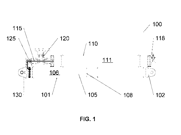
[0042] Referring now to FIG. 1, FIG. 1 illustrates a side view of a hydro-
pneumatic cylinder
isolator 100 having a secondary reservoir 110 attached to the primary
reservoir 105 of the isolator
100 by a fluid passageway 115, manifold 125 and optional valve 120 in
accordance with an
embodiment of the present disclosure. In one embodiment, the isolator
suspension system 100
comprises a cylinder 101, a primary reservoir 105 comprising a primary
reservoir volume 106
disposed within the cylinder 101, a secondary reservoir 110 comprising a
secondary reservoir
volume 111 disposed within the secondary reservoir 110, a primary duct 115
connecting the
primary reservoir 105 to the secondary reservoir 110 via a primary duct
opening (not shown) in
end cap 130 attached to cylinder 101, the primary duct 115 comprising a duct
cross sectional area
(not shown), and a duct length (not shown) such as to desirably provide for
flow control of a fluid
flowing between the primary 105 and secondary 110 reservoirs, for example.
Isolator 101 may
further optionally comprise a valve 120 such as a flow control valve, for
controlling a flow rate of
a fluid between the primary 105 and secondary 110 reservoirs by, for example,
opening and closing
the primary duct 115, and a manifold 125 disposed within the primary duct 115.
Isolator 100 may
be attached to a movable suspended load or weight by means of the suspension
end connector 102,
and to a base or support at the other end of isolator 100 by end cap 130. In
one embodiment, end
cap 130 may be retrofitted to a commercially available single cylinder hydro-
pneumatic isolator
cylinder 101 such as to provide for attachment and fluid connection with
secondary reservoir 110.
In one embodiment primary 105 and secondary 110 reservoirs may comprise at
least one
compressible fluid such as air, nitrogen or another suitable compressible
fluid, for example.
100431 In one embodiment, the primary duct 115 may comprise a continuous,
substantially
uniform cross sectional shape along the length of the duct 115, and may
comprise a characteristic
cross sectional area. In a particular embodiment, the duct 115 may comprise a
tube having a
19
CA 02947906 2016-11-03
WO 2015/168790 PCT/CA2015/050396
substantially circular cross sectional shape. In one embodiment, the length of
the primary duct 115
may typically comprise the total length of the duct 115 extending between the
primary 105 and
secondary 110 reservoirs. In an alternative embodiment, the isolator 110 may
additionally
comprise one or more additional secondary reservoirs (not shown) each
comprising an additional
reservoir volume (not shown). In one such embodiment, each additional
secondary reservoir (not
shown) may comprise an additional secondary duct (not shown) fluidly
connecting the additional
reservoir to the primary reservoir 105, and each additional secondary duct
(not shown) may also
comprise a secondary flow control valve (not shown) to control the flow of a
fluid between such
additional secondary reservoirs (not shown) and the primary reservoir 105, for
example.
[0044] In one embodiment, isolator 100 may comprise a primary piston 108
disposed and
moveable within cylinder 101 such as to provide for compression or extension
of the isolator 100
for corresponding compression of the fluid contained in primary reservoir 105
to provide
absorption of shock or impact through the compression stroke of piston 108
within isolator
cylinder 101. In an optional embodiment, each secondary reservoir, such as
secondary reservoir
110 may also optionally comprise a secondary piston (not shown).
[0045] In a particular embodiment, manifold 125 within primary duct or flow
passageway 115
may additionally comprise one or more components of a control system (not
shown) for controlling
a flow rate of the fluid between the primary 105 and secondary 110 reservoirs.
In one such
embodiment, manifold 125 may comprise one or more pressure sensors (not
shown), flow limiters
or switches (not shown), or other control system components such as for a
mechanical,
electromechanical or electronic fluid flow control system, for example. In a
particular such
embodiment, other optional control system components such as a
microcontroller, PLC,
microprocessor, switches or other suitable control system components (not
shown) such as for a
mechanical, electromechanical or electronic fluid flow control system may be
attached to or
integrated with the end cap 130, manifold 125, valve 120 and secondary
reservoir 110 of isolator
100 such as for implementing automatic, semi-active or manually adjustable
fluid flow control of
a fluid through primary duct 115 between primary reservoir 105 and secondary
reservoir 110. In
one embodiment, isolator 100 may also comprise a fluid pressurization port 118
such as for adding
or withdrawing fluid from secondary reservoir 110 to set or adjust the
pressure of a fluid in
secondary reservoir 110, for example.
CA 02947906 2016-11-03
WO 2015/168790 PCT/CA2015/050396
[0046] Referring now to FIG. 2, FIG. 2 illustrates a perspective view of a
hydro-pneumatic cylinder
isolator 200 in accordance with an embodiment of the present disclosure, and
substantially similar
to the isolator 100 shown in FIG. 1. Isolator 200 comprises a secondary
reservoir 210 attached to
the cylinder 201 of the isolator containing the primary reservoir of the
isolator. Similar to as shown
in FIG. 1, secondary reservoir 210 is fluidly connected to the primary
reservoir in cylinder 201 of
the isolator 200 by a primary duct or fluid passageway which comprises a
manifold 225, and
optionally also a flow control valve 220 in accordance with an embodiment of
the present
invention. Further, isolator 200 also comprises an end cap 230 which may be
retrofitted to a
commercially available single cylinder hydro-pneumatic isolator cylinder 201
such as to provide
for attachment and fluid connection with secondary reservoir 210 through a
primary duct opening
(not shown) in the end cap 230, and a primary duct (not shown). In one
embodiment primary (not
shown) and secondary 210 reservoirs may comprise at least one compressible
fluid such as air,
nitrogen or another suitable compressible fluid, for example. Isolator 200 may
be installed to
suspend a movable suspension load or occupant seat such as by movable
suspension end connector
202, and to a base by end cap 230 at the other end of the isolator 200.
Similar to as shown in FIG.
1, in one embodiment isolator 200 may also comprise a fluid pressurization
port 218 such as for
adding or withdrawing fluid from secondary reservoir 210 to set or adjust the
pressure of a fluid
in secondary reservoir 210, for example.
[0047] Referring now to FIG. 3, FIG. 3 illustrates a perspective view of a two
(2) position (or
detent) passive isolator reservoir volume selector system 300 attached to a
marine vehicle seat base
302 in accordance with an embodiment of the present disclosure. In one
embodiment, a selector
lever or switch 310 may be connected to a fluid flow valve (not visible) which
is connected to
control fluid flow from a primary reservoir to a secondary reservoir of an
isolator suspension
system according to the invention (not visible) which provides shock
adsorption between seat base
302 and a movable suspended portion (not shown) of the seat which may slide or
otherwise move
along a back rail or support 301 of the seat. Selector lever or switch 310 may
enable a user to
manually select a valve position and correspondingly control the flow of a
fluid from the primary
to secondary reservoirs of the isolator (not visible) by rotating the selector
lever or switch 310. In
one such embodiment, a first indicia 330 may represent a heavy suspension load
or seat occupant
weight condition corresponding to a closed position of a fluid flow control
valve (not visible) when
selected by moving the selector lever or switch 310 to first indicia 330. In
such an embodiment,
21
CA 02947906 2016-11-03
WO 2015/168790 PCT/CA2015/050396
a second indicia 320 may represent a light or low suspension load or seat
occupant weight
condition corresponding to an open position of a fluid flow control valve (not
visible) when
selected by moving the selector lever or switch 310 to second indicia 320.
[0048] Referring to FIG. 4, FIG. 4 illustrates a rear perspective view of a
shock-absorbing vehicle
seat 400 incorporating a hydro-pneumatic cylinder isolator 401 having a
secondary reservoir (not
visible behind isolator 401) in accordance with an embodiment of the present
invention. In one
such embodiment, isolator 401 may desirably be attached between a fixed base
440 of the seat and
to a moveable suspended portion 450 of the vehicle seat 400 such as by the
moveable suspension
end connector 402 of the isolator 401. Accordingly, isolator 401 comprising a
secondary reservoir
(not visible) may desirably provide for close integration and installation
within a suitable shock
absorbing suspended vehicle seat 400. In one particular embodiment, a hydro-
pneumatic cylinder
isolator 401 having a secondary reservoir (not visible behind isolator 401) in
accordance with an
embodiment of the present invention may desirably provide for retrofittable
installation in an
existing shock absorbing vehicle seat design 400, desirably allowing for cost
effective adoption
and installation into existing vehicle applications such as high speed marine
vehicles (boats), and
other suitable land, air and space vehicle applications.
[0049] In an optional embodiment, configuration of the suspension system
comprising the isolator
100 such as determining desired values for the cross sectional area and length
of the primary duct
or fluid passageway 115 and/or area of a primary duct opening (not shown) in
end cap 130 may
optionally be determined by using an algorithm or model to have parameters to
desirably maximize
the efficiency of the secondary reservoir 110 in achieving shock mitigation by
isolator 100. In
one optional embodiment, an additional parameter which may optionally be
determined by using
an algorithm or model is a desired control switching point or weight to switch
between use of
primary reservoir 105 only and use of combined primary and secondary
reservoirs 105 and 110 in
operation of the isolator 100. In one embodiment, the secondary reservoir 110
may be larger in
volume than the primary reservoir 105. In an alternative embodiment, the
secondary reservoir 110
may be smaller in volume than the primary reservoir 105. In an exemplary
embodiment directed
to applications in seat suspension systems, a defined range of suspension
loads may comprise a
defined range of seat occupant weights, for example.
[0050] In an optional embodiment directed to application in suspension seats
in marine vehicles
(boats), a formula or mathematical model may optionally be employed to
determine the primary
22
CA 02947906 2016-11-03
WO 2015/168790 PCT/CA2015/050396
duct or fluid passageway 115 size and shape in relation to the primary 105 and
secondary 110
reservoir volume(s) and optionally also the control switching points for input
conditions (occupant
weight and sea conditions). In one such embodiment, the suspension system 100
may be controlled
and adjusted manually, automatically (for example, by automatically
controlling a valve using a
computer and sensors), or by a hybrid of manual and automatic control
features, in order to
continually, actively, and repeatedly monitor the state of the suspension
system. The switching
may be manual, electromechanical or computer controlled, for instance in
response to sensors on
the vehicle and or manual and automatic inputs.
[0051] In one such optional embodiment, there may be a target switching point
between use of a
single reservoir, or reservoirs, for example, between the use of only the
primary reservoir 105 and
use of both the primary 105 and secondary 110 reservoirs, where the switching
point is optionally
determined by measuring a peak-to-peak ratio R between the acceleration of a
target object, such
as a seat in a marine vehicle, and the acceleration of the vehicle, for
example, the deck of a marine
vehicle, or some function of this ratio R including but not limited to a
function that combines it
with other factor(s) in order to select a switching point that minimizes the
input acceleration(s)
applied to the suspended occupant portion of the seat. In one such optional
embodiment, a
reservoir volume selection procedure switching point selection procedure for a
system
incorporating two reservoir volumes, one primary reservoir 105 permanently
connected within the
cylinder 101 of the isolator 100 and a secondary reservoir 110 that can be
switched between being
fluidly connected or isolated from the primary reservoir 105 may be described
as follows:
[0052] Reservoir volume determination in one optional embodiment
First, occupant weights or suspension load are defined with a probability
distribution, typically a
Normal distribution. This may then used to create a probability distribution
for the mass suspended
on the isolator.
Second, a desired relation between natural frequency of the isolator system
(isolator and suspended
mass) and stroke position may be defined. In one embodiment, possible
relations include one in
which the rate of change of the natural frequency with stroke position is
substantially constant.
Third, one reservoir volume may be selected so that the defined relation
between the natural
frequency and isolator stroke is obtained for a suspended weight that
represents light occupants
(the low end of the desired suspended weight range)
23
CA 02947906 2016-11-03
WO 2015/168790 PCT/CA2015/050396
Fourth, repeat the third step for a second reservoir volume for a suspended
weight that represents
heavy occupants (the high end of the desired suspended weight range).
10053] Switching point determination process in one optional embodiment
First, an input acceleration representative of the vertical deck acceleration
encountered at sea is
defined.
Second, the peak to peak SE-AT values over the range of suspended weights
using the input
acceleration from the first step may be calculated or experimentally measured
for each of two
cases: a) with the valve 115 open and, b) with the valve 115 closed.
In one embodiment, a switching point, W
switch , may be selected to desirably minimize the average
of the peak to peak SE-AT values over the complete range of suspended weights
according to the
below formula:
f (wswitch) ----
fw switch TA, S(W)
w in
(W) fWSw.itchS dWI
mm valve open+ f ffWmax w s(w)
m 1
W switch
Wmax
W switch S (W) dW
f
valve closed
Wmax ¨ Wmill
Where,
W weight
Wmin minimum suspended weight
Wmax maximum suspended weight
Wswitch switching point or switching weight
f (wswitch) average value of the peak to peak SE-AT value as a function of the
switching weight
S(W) the SE-AT value as a function of weight
24
CA 02947906 2016-11-03
WO 2015/168790 PCT/CA2015/050396
[0054] In one such optional embodiment, the value of Wswitch may desirably be
placed on a label
on the suspended seat such as next to a manual control for the valve 115, to
provide for manual
switching by the seat operator, or alternatively in a case of automatic
switching such as by an
electronic control system, the value can be incorporated into control software
or logic.
[0055] In further alternative embodiments, additional criteria may be used to
select a switching
weight including, for example, a criterion that the SE-AT value not to exceed
a particular limit. In
one embodiment, the desired minimization of input acceleration(s) may be
defined in various
ways, including but not limited to minimizing the average of the function
which incorporates the
ratio R across all suspended weights, or by minimizing the maximum value of
the function
incorporating the ratio R at any suspended weight.
[00561 In a further optional embodiment, a relationship among the cross
sectional area of the
primary duct 115, cross sectional area of the primary piston 108 disposed
within the primary
reservoir 105, and maximum speed of the primary piston 108 may be defined as
follows:
Aduct > C1 Apiston Vmax
wherein
Aduct is the cross sectional area of the primary duct 115 [sq. in.],
Apiston is the cross sectional area of the primary piston 108 [sq. in],
Vmax is the maximum velocity of the primary piston 108 [is], and
CI is a constant substantially equal to 3.5 x 10⁻⁴ [s/in]
In an optional embodiment, the value of CI may range between about 3.0 x 10⁻⁴
and 4.0 x 10⁻⁴
[s/in]. In a further optional embodiment, Ci is a constant equal to 3.5 x 10⁻⁴
[s/in].
In another optional embodiment, a relationship between the length of the
primary duct 115 and the
primary duct cross sectional area may be defined as follows:
0 < Lduct < C2 Aduct
wherein
Lduct is the length of the primary duct 115 [in.],
Aduci is the cross sectional area of the duct 115 [sq. in.], and
C2 is a constant substantially equal to 76.5 [in-'].
CA 02947906 2016-11-03
WO 2015/168790 PCT/CA2015/050396
In an optional embodiment, the value of C2 may range between about 75 and 78
[in']. In a further
optional embodiment, C2 is a constant equal to 76.5 [in-'].
[0057] Also in a particular embodiment directed to marine vehicle
applications, the cylinder 101
of isolator 100 may be connected to the seat of a marine vehicle user in order
to dampen the
gravitational forces, or G-forces which may be encountered in high speed
marine operations, and
which may typically range from about 0-16g for example in an embodiment
directed to a high
speed marine vehicle.
[0058] In another particular embodiment, the length and cross sectional area
of the primary duct
or fluid passageway 115 between the primary reservoir 105 of the isolator 100
and the secondary
reservoir 110 may be shorter and larger, respectively, than the corresponding
length and cross
sectional area of a fluid passageway such as a fluid bypass in conventional
single reservoir
isolators for suspended seats. In one optional embodiment according to the
present invention, a
ratio between the length and cross sectional area of the primary duct 115 and
the volume of the
primary 105 and secondary 110 reservoirs may desirably be determined by using
at least one of a
mathematical theory or model and experimental testing results to achieve a
desirably consistent
and high level of shock mitigation across different suspension payloads such
as seat occupant
weights of a range of occupants of a suspended seat.
[0059] According to one embodiment of the invention, a challenge associated
with suspension of
vehicle seats is to provide a desirably simple, easy to use suspension system
for a suspended
vehicle seat such as a marine vehicle seat. Often in certain embodiments
directed to high speed
marine vehicles, the operator or user of a seat may be traveling in high
impact conditions,
sometimes at night or in variable weather such as fog, rain, sleet or spray,
with large wave and
swell heights. For seat suspension systems requiring control input by an
operator, control
selections must be simple and accessible from harnessed seating positions.
Certain currently
known or available marine seats may provide undesirably complex control inputs
requiring
instruction manuals to select between multiple seat suspension controls and
multiple detents on
each control, leading to input errors, thereby increasing the risk of injury
or accident or suspension
maladjustment. In one embodiment according to the present invention, a seat
suspension system
comprising primary and secondary reservoirs and requiring no user control
input may be provided.
In another embodiment according to the invention, a simple two (2) position
(or detent) seat
26
CA 02947906 2016-11-03
WO 2015/168790 PCT/CA2015/050396
suspension adjustment is provided for control of a valve 120 between a primary
105 and secondary
110 reservoirs of a seat suspension isolator 100, in order to achieve
desirably similar and effective
shock mitigation in a marine seat isolator for seat occupant weights over a
wide range, such as
from 90 pounds to 180 pounds or up to 300 pounds or more, while maintaining a
simple user
control.
[0060] In an alternative embodiment, switching between primary 105 and one or
more secondary
110 reservoirs can be controlled automatically, such as based on a sensor
identifying the weight of
the suspension payload such as the weight of an occupant of a marine seat,
which may in one
aspect include for instance the seat user and his or her equipment and
clothing, and optionally also
the weight of the empty suspended portion of the seat. In another embodiment,
such switching
may be controlled based on one or more sensors identifying one or more
parameters such as
compression travel of the isolator 100, acceleration profile of the shock or
input acceleration, or
other suspension related parameters, for example. In an additional embodiment
the isolator 100
with one or more secondary reservoirs 110 may be semi-actively controlled,
such as having control
of switching between primary and secondary reservoirs (and thereby affecting
damping of the
suspension system) be achieved by response from one or more sensors and
control by a
programmable logic controller (PLC), microcontroller or other suitable
mechanical,
electromechanical or electronic control system, for example.
[0061] In a further embodiment, a passive control system comprising primary
and secondary
reservoirs and requiring no input from a user may be provided, and in another
embodiment a
passive control system comprising primary and secondary reservoirs and
comprising a two (2)
option or position selector for selecting between light and heavy suspension
payloads may be
implemented, such as to desirably provide improved shock mitigation
performance over a range
of suspension payloads relative to existing semi-active systems, while also
providing simpler
components and lower costs to manufacture and desirably also to maintain and
operate.
[0062] A particular embodiment of the present isolator system 100 may be
adapted for a marine
environment by providing suspension components manufactured at least in part
of light aluminium
and/or stainless steel machined components resistant to corrosion in salt
water, versus typically
heavy, larger components of welded steel which may be typical for applications
to land vehicles
[0063] An additional embodiment of the present invention may employ an
isolator 100 with air
switch engagement for actuation. Another embodiment may comprise an isolator
for a seat in
27
CA 02947906 2016-11-03
WO 2015/168790 PCT/CA2015/050396
military vehicles with one or more secondary reservoirs 110 automatically
engageable for
unexpected or emergency situations, such as blast attenuation for example.
[0064] Information as herein shown and described in detail is fully capable of
providing the
above-described advantages of the present disclosure, the presently preferred
embodiment of the
present disclosure, and is, thus, representative of the subject matter which
is broadly contemplated
by the present disclosure. The scope of the present disclosure fully
encompasses other embodiments
and is to be limited, accordingly, by nothing other than the appended claims,
wherein any reference
to an element being made in the singular is not intended to mean "one and only
one" unless
explicitly so stated, but rather "one or more." All structural and functional
equivalents to the
elements of the above-described preferred embodiment and additional
embodiments are hereby
expressly incorporated by reference and are intended to be encompassed by the
present claims.
[0065] Moreover, no requirement exists for a system or method to address each
and every
problem sought to be resolved by the present disclosure, for such to be
encompassed by the
present claims. Furthermore, no element, component, or method step in the
present disclosure is
intended to be dedicated to the public regardless of whether the element,
component, or method
step is explicitly recited in the claims. However, that various changes and
modifications in form,
material, work-piece, and fabrication material detail may be made, without
departing from the spirit
and scope of the present disclosure, as set forth in the appended claims, are
also encompassed by
the present disclosure.
INDUS TRIAL APPLICABILITY
[0066] The present disclosure industrially applies to a shock absorbing
apparatus and system for
a suspension of a single suspended component, such as a seat for example, and
having a plurality
of pneumatic reservoirs including a primary and at least one secondary
reservoir. More
specifically, the present disclosure industrially applies to shock absorbing
apparatus and systems
for mitigating force applied to a seat in a vehicle, such as a marine vehicle
for example, such that
the g forces or other impact forces due to operational conditions, such as
high speed adverse
environments including wave action, are desirably minimalized with respect to
the suspended
human passenger or user, or other impact-sensitive suspension load such as
impact-sensitive
equipment. Even more specifically, the present disclosure industrially applies
to shock absorbing
systems with a passive control system which desirably optimizes the length and
cross sectional
28
CA 02947906 2016-11-03
WO 2015/168790 PCT/CA2015/050396
area of a primary duct or fluid passageway connecting a secondary pneumatic
reservoir to the
primary reservoir of an isolator, and also the volume of the secondary
reservoir in a manner to
desirably optimize shock mitigation for a range of suspended weights such as
the weight of an
occupant on a suspended seat comprising the system. Other industrial
applications include, but
are not limited to, facilitating shock mitigation to human users in blasts or
explosions, marine,
land, air and space vehicle seat shock absorbing, and other isolator systems
for seats, or for other
suspension systems including hydro-pneumatic isolators.
[0067] The scope of the present disclosure fully encompasses other embodiments
and is to be
limited, accordingly, by nothing other than the appended claims, wherein any
reference to an
element being made in the singular is intended to mean "one or more", and is
not intended to mean
"one and only one" unless explicitly so stated. All structural and functional
equivalents to the
elements of the above-described preferred embodiment and additional
embodiments are hereby
expressly incorporated by reference and are intended to be encompassed by the
present claims.
Moreover, no requirement exists for an apparatus or method to address each and
every problem
sought to be resolved by the present disclosure, for such to be encompassed by
the present claims.
Furthermore, no element, component, or method step in the present disclosure
is intended to be
dedicated to the public regardless of whether the element, component, or
method step is explicitly
recited in the claims. However, that various changes and modifications in
form, material, work-
piece, and fabrication material detail may be made, without departing from the
scope of the present
disclosure, as set forth in the appended claims, are also encompassed by the
present disclosure.
29