Note: Descriptions are shown in the official language in which they were submitted.
CA 02948518 2016-11-15
CONTINUOUS HEATING DEVICE FOR COIL SPRINGS AND HEATING
METHOD USING THE SAME DEVICE
BACKGROUND OF THE INVENTION
1. Field of the invention
The present invention relates to a continuous heating
device for coil springs that are foLmed in the shape of a
coil by using a steel wire for a spring. More
specifically, the present invention relates to a continuous
heating device for coil springs, which provides an
automated process for continuously heating coil springs
through an electrical induction heating process in which
the coil springs do not come in direct contact with a heat
source while moving the coil springs by using a conveyor
chain with a gradual increase in the rotational speed of
the coil spring by using tapered rollers, and which drops
the heated coil springs into a cooling tank that is filled
with a cooling fluid, such as water or oil, to then be
cooled in order to thereby improve the manufacturing
productivity and the quality of the coil spring. In
addition, the present invention further relates to a
continuous heating method for coil springs, using the same
device.
1
CA 02948518 2016-11-15
2. Description of the Prior Art
In general, the coil spring may be used as a buffer to
absorb or accumulate energy by using an elastic force of
the steel wire, or may be used for the purpose of securing
operating functions of various mechanical components by
using the restoring elasticity that is a repulsive force
after compression.
Meanwhile, the most common type of coil spring is made
by winding a steel wire in a spiral folio., and the coil
M spring is manufactured through a basic inspection of a raw
material, a surface peeling process, a heating process, a
coil forming process, quenching, and tempering.
The coil spring, which has been manufactured as
described above, is subject to a series of surface
treatment processes in order to improve the mechanical
properties of the coil spring and to increase the strength
thereof. The surface
treatment may be made through a
tempering process, a shot peening process, a pre-treatment
process, and a painting process after completing the
forming and quenching processes of the coil spring.
Thereafter, the product is output through a load testing
process, a marking process, and a final inspection process.
Typically, the foLmed coil spring is input to the
combustion heating furnace to then be heated about 980 C,
2
CA 02948518 2016-11-15
or higher, which is higher than the A3 transfoimation
point(the A3 transformation point of steel is 910 C.:), for
the heat treatment (quenching).
However, if the heat treatment process is automated to
be a continuous process, it is difficult to evenly heat the
entire area of the coil spring so that the decarburized
portion (the portion of which the amount of carbon
decreases on the surface due to the oxidization of the
carbon on the surface into carbon monoxide when steel is
M heated in the air) of the coil spring, which is left on the
surface of the material after the surface processing, may
remain even after heating in order to thereby reduce the
endurance life of the coil spring.
Korea Patent No. 10-0752224 discloses a high-frequency
induction type heat treatment device for a shaft.
According to the invention, a shaft is input between two
rotational rollers for an automated continuous heat
treatment of a shaft for automobile parts, and the shaft is
moved by a conveyor chain while being rotated. Then, the
shaft is heated by a high-frequency heating device that is
installed in the inteLmediate position of the shaft
movement path.
In the high-frequency induction heating type of heat
treatment device for a shaft, a pair of rollers that are
3
CA 02948518 2016-11-15
rotated on both sides of the lower portion of the shaft may
be heated at the same time the shaft is heated so that the
rollers exhibit a thermal expansion in the longitudinal
direction thereof. Therefore, a high-frequency coil unit
for the heat treatment is made to be very short in a ring
shape and the shaft is immediately cooled by using a shaft
cooling unit.
However, with the structure described above, since it
takes a long time to sufficiently heat the shaft, the
M moving speed of the shaft may slow down so that the number
of shafts that are produced per unit hour may decrease and
the productivity may be dropped.
In addition, when the coil spring is input between a
pair of rollers that are disposed to be parallel with each
other in order to perfoLm the heat treatment of the coil
spring by using the high-frequency induction heating type
of heat treatment device for a shaft, the coil spring may
pop out in the rotational direction of the roller because
the coil spring is shorter and lighter than the shaft.
Therefore, it is difficult to apply the high-frequency
induction heating type of heat treatment device to the coil
spring.
An induction hardening process of a helical spring and
a device thereof, which are disclosed in US Patent
Publication No. 2008/0128057, provides a technique in which
4
CA 02948518 2016-11-15
a helical spring is positioned on a mandrel and is
induction-heated while the rotation of the spring is made
by being moved on a caterpillar. However, the device has a
complicated spring-input process and a complex mechanical
configuration, and cannot significantly improve the
productivity.
In addition, US Patent No. 8912472 discloses a device
for heating a coil spring by using the electric induction
heating method while rotating the coil spring on a pair of
M rotational rollers that are positioned to be parallel with
each other to rotate in the same direction. However, when
the coil spring is vertically dropped onto the rotational
rollers for the input of the coil spring, the coil spring
may pop out due to the rotation of the rollers.
FurtheLmore, whenever the coil spring is dropped, the
rotational rollers are to be opened wide. Therefore, the
continuous heating device requires a complicated
configuration and it is difficult to improve the
productivity.
In addition, since the heating device has a structure
of downwardly inputting the coil spring to the rotational
rollers from above, which is suitable to be applied to a
big coil spring, it is not suitable for manufacturing a
small coil spring.
5
CA 02948518 2016-11-15
PRIOR REFERENCES
1. Korean Patent No. 10-0752224 (High-frequency
Induction Heating Type Heat-treatment Device for Shafts)
2. US Patent Publication No. 2008-0128057 (Process
of and Device for Induction-hardening Helical Springs)
3. US Patent No. 8912472 (Induction Heating of
Springs)
SUMMARY OF THE INVENTION
The present invention has been made to solve the
problems above. An aspect of the present invention is to
provide a continuous heating device for coil springs and a
continuous heating method for coil springs using the same
device in which a coil spring that is formed of a steel
wire is heated by using an electric induction coil that is
a heating device that does not come in direct contact with
a heated object while being moved, and in which the coil
spring may be prevented from popping out when it is
supplied and a simple structure of the device and a stable
continuous operation thereof may be secured with the
improvement of the productivity and the quality of the
produced coil spring.
In addition, the present invention provides a
6
CA 02948518 2016-11-15
continuous heating operation of a coil spring in which:
central rotation axes of a pair of tapered rollers are
arranged to not be parallel with each other; the inner
surfaces of the pair of tapered rollers are arranged to be
parallel with each other when they are viewed from above;
the upper surfaces of the tapered rollers are arranged to
be horizontal when they are viewed from the side; a push
rod that is mounted on a conveyor chain moves the coil
spring; the pair of tapered rollers allow the coil spring
M to pass through an electric induction coil while gradually
increasing the rotational speed of the coil spring from a
low speed to a high speed; and the coil spring that is
input to the front end portion of the tapered rollers
burrows further into the gap between the pair of tapered
rollers as it goes from the front end portion to the rear
end portion so that the coil spring may be prevented from
popping out to then be stable.
The present invention also provides an automated
device for heating coil springs for mass production, which:
provides a reliable automated heating process of the coil
spring in order to thereby improve the productivity; allows
the produced coil springs to have the same size, strength,
and property in order to thereby enhance the reliability of
quality; and enables easy installation and maintenance by
adopting a relatively simple structure.
7
CA 02948518 2016-11-15
In addition, an embodiment of the present invention
may maintain the smooth operation even when the tapered
rollers are thermally expanded in the longitudinal
direction due to the heating of an electric induction coil
by installing an elastic buffer spring in the support shaft
of the rear end portion of the roller, and may provide a
simple power transmission mechanism that uses a universal
joint for transmitting a driving force to the tapered
roller in order to effectively transmit a driving force to
M the shafts of a pair of tapered rollers, which are not
parallel with each other.
According to an embodiment of the present invention, a
continuous heating device for coil springs may include: a
pair of tapered rollers 20 that support and rotate the coil
spring 10, that have a cross-section diameter that
increases as it goes from the front end portion to the rear
end portion, and that have rotational inner surfaces that
are arranged to be parallel with each other while the
central rotation axes thereof are not parallel with each
other; a conveyor chain 43 that has a push rod 41 installed
to move the coil spring 10; and a driving unit 60 for
providing a rotational driving force to the pair of tapered
rollers 20.
In addition, the pair of tapered rollers 20 may be
maintained such that the upper surfaces thereof are
8
CA 02948518 2016-11-15
horizontal.
In addition, the pair of tapered rollers 20 may be
formed of a non-magnetic metal roller 21 and a ceramic
roller 22.
In addition, the device may further include a roller
support shaft 50 and an elastic buffer spring 51 in order
to buffer the elongation of the tapered roller 20 in the
longitudinal direction.
In addition, the device may further include a
M universal joint 55 that effectively transfers a rotational
force between a pair of driving shafts that are arranged to
be parallel with each other in the driving unit 60 and a
pair of tapered rollers 20 that are arranged to not be
parallel with each other.
In addition, the driving unit 60 may transfer a
rotational driving force to two roller shaft gears 63 by
using a single power shaft gear 61.
FurtheLmore, the push rod 41 may be foLmed of a non-
conductive ceramic material.
In addition, the device may further include an
induction coil power controller 33 that controls the amount
of electric power applied to the electric induction coil
31.
In addition, the device may further include a cooling
tank 71 that is filled with a cooling fluid to quench the
9
CA 02948518 2016-11-15
coil spring 10.
In addition, a continuous heating method for coil
springs may include: inputting and rotating a coil spring
by means of a pair of tapered rollers 20 such that the
5 coil spring 10 does not pop out of the tapered rollers 20,
the tapered rollers 20 having a cross-sectional diameter
that increases as it goes from the front end portion to the
rear end portion and having rotational inner surfaces that
are arranged to be parallel with each other while the
M central rotation axes thereof are not parallel with each
other; moving the coil spring 10 by means of a conveyor
chain 43 that has a push rod 41 installed therein; and
heating the coil spring by the high-frequency induction
magnetic field while moving the coil spring 10 in the
section of the electric induction coil 31 by using the
tapered rollers 20.
In addition, the method may further include dropping=
the heated coil spring 10 into the cooling tank 71.
According to the continuous heating device for coil
springs and the continuous heating method for coil springs
using the same device, the inner surfaces of a pair of
tapered rollers are arranged to be parallel with each other
when they are viewed from above while the central rotation
axes of the tapered rollers are arranged to not be parallel
with each other, and the upper surfaces of the tapered
CA 02948518 2016-11-15
rollers are arranged to be horizontal when they are viewed
from the side so that the push rod may move the coil
spring. FurtheLmore, the pair of tapered rollers may allow
the coil spring to pass through the electric induction coil
while gradually increasing the rotational speed of the coil
spring from a low speed to a high speed in order to thereby
prevent the coil spring from popping out in the rotational
direction of the roller when it is input because the coil
spring is input to the front end portion of the tapered
M roller where the circumferential speed of the tapered
roller is low. In addition, even when the circumferential
speed of the tapered roller increases to a high speed, the
coil spring may be stably moved between the tapered rollers
without popping out of the same in order to thereby heat
the entire area of the coil spring uniformly and in order
to thereby improve the quality reliability of the produced
coil spring.
In addition, the present invention can rapidly heat a
lot of coil springs automatically and continuously without
adopting a complicated driving means in order to thereby
improve the productivity, and can secure the continuous
mass production and the improvement of the productivity
even with a simple structure.
In addition, a portion of the tapered roller, which
corresponds to the electric induction coil among the whole
11
CA 02948518 2016-11-15
of the tapered roller, is made of a ceramic material in
order not to be significantly affected by the magnetic
field caused by the high-frequency induction that is
generated in the electric induction coil so that the
continuous heating device may be prevented from being
unnecessarily heated. In addition, even though the tapered
roller is thermally expanded by heating, the smooth
rotation of the tapered roller may be maintained by means
of the elastic buffer spring that is mounted on the support
shaft of the rear end portion of the roller.
In addition, the driving force may be transferred to
the shafts of a pair of tapered rollers, which are not
parallel with each other, from a single driving force
source by using a universal joint. Therefore, even though
the shafts of the pair of tapered rollers are not
horizontal and are not parallel with each other, the
driving force can be effectively transferred with a simple
structure.
BRIEF DESCRIPTION OF THE DRAWINGS
The above and other aspects, features and advantages
of the present invention will be more apparent from the
following detailed description taken in conjunction with
the accompanying drawings, in which:
12
CA 02948518 2016-11-15
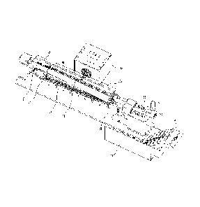
FIG. 1 is a perspective view of a continuous heating
device for coil springs, according to a preferred
embodiment of the present invention.
FIG. 2 is a view illustrating a continuous heating
device for coil springs 10 when it is viewed from above.
FIG. 3 is a view illustrating a continuous heating
device for coil springs when it is viewed from the side.
FIG. 4 is a view showing the front end portion and the
rear end portion of a pair of tapered rollers 20.
FIG. 5 is an enlarged view of a rear-end support shaft
of the tapered roller 20.
FIG. 6 is a view showing the installation state of
gears that transfer a driving force from the driving unit
60 to the shaft of the tapered roller 20.
DETAILED DESCRIPTION OF THE EXEMPLARY EMBODIMENTS
Technical teLms that are used in the present
specification are intended to describe only a specific
embodiment, and are not intended to limit the present
invention.
Further, the technical terms in the specification
should be construed as a meaning generally understood by
those skilled in the art unless the terms are defined as
another meaning and should not be construed as an
CA 02948518 2016-11-15
excessively inclusive meaning or an excessively exclusive
meaning.
In addition, a singular expression used in the
specification includes a plural expression as long as they
are clearly distinguished in the context. In the present
disclosure, the term "comprise" or "include" should not be
construed as necessarily including all of various elements
or various steps disclosed herein, and it should be
understood that some of the elements or steps may not be
M included, or additional elements or steps may be further
included.
In addition, the same reference numeral denotes the
same element throughout the present specification.
Hereinafter, a continuous heating device for coil
springs and a continuous heating method for coil springs
using the same will be described with reference to FIGS. 1
to 6.
FIG. 1 shows a continuous heating device for coil
springs, according to a preferred embodiment of the present
invention.
In the present invention, a conveyor chain 43 is
installed under a pair of rotating tapered rollers 20. The
tapered rollers 20 have an input section of the coil spring
10 in the front end portion thereof and have a heating
section of the coil spring 10 in the rear end portion
14
CA 02948518 2016-11-15
thereof. The coil spring 10 may be rotated and moved to
then be heated by an electric induction coil 31 that is
installed above the heating section of the coil spring 10
of the tapered rollers 20.
In the present invention, the pair of tapered rollers
20 may be shaped into a truncated cylinder that has the
minimum diameter in the front end and the maximum diameter
in the rear end so that the circumferential speed of the
front end portion may be reduced by 1/2 to 1/3 of the
M circumferential speed of the rear end portion when the
tapered roller 20 is rotated. That is, the circumferential
speed may be designed such that the coil spring 10 does not
pop out when the coil spring 10 is input to the front end
portion (i.e., the input section of the coil spring 10) of
the tapered roller 20.
It is preferable to maintain the upper surface of the
tapered roller 20 to be horizontal while the central
rotation axis of the tapered roller 20 is tilted downwards
as it goes from the front end portion to the rear end
portion in order to thereby allow the coil spring 10 to
horizontally move on the tapered rollers 20.
The pair of tapered rollers 20 are required to be
spaced a constant distance from each other in order for the
coil spring 10 to move on the same. Therefore, it is
preferable to install the central rotation axes of the pair
CA 02948518 2016-11-15
of tapered rollers 20 to be spaced more in the rear end
portion. Even though the diameter of the tapered roller 20
becomes larger as it goes toward the rear end portion
thereof, the gap between the tapered rollers 20 may be
maintained to be constant. Thus, the coil spring 10 that
is placed on the pair of tapered rollers 20 may be
maintained to be stable between the tapered rollers 20
without popping out of the same while moving downstream as
shown in FIG. 4.
The coil spring 10, which is placed on the pair of
tapered rollers 20 and is rotated by the rotation of the
tapered rollers 20, is transferred by the push rod 41 that
is mounted on the conveyor chain 43 to pass through the
electric induction coil 31. When the coil
spring 10 is
initially placed on the pair of tapered rollers 20, the
rotational speed thereof is low. Although the rotational
speed of the coil spring 10 increases as it moves toward
the rear end portion, the coil spring 10 may be stable
without popping out in order to thereby improve the
productivity in the operation of heating the coil spring
10.
The pair of tapered rollers 20 may be supported to be
rotatable by means of rotational bearings that are
positioned in the front end portion thereof and by means of
rotational bearings that are positioned in the roller
16
CA 02948518 2016-11-15
support shaft 50 that is coupled to the rear end portion of
the rollers, and a rotational driving force may be supplied
from the driving unit 60.
The tapered roller 20 is separated into the input
section of the coil spring 10 and the heating section of
the coil spring 10 based on the start point of the electric
induction coil 31. Preferably, the
input section of the
coil spring 10 may be made of a non-magnetic metal roller
21 and the heating section of the coil spring 10 may be
M made of a ceramic roller 22.
Preferably, the non-magnetic metal roller 21 on which
the coil spring 10 to be heat-treated is initially placed
may be made of a metal that is hardly heated by the
magnetism in order not to be easily heated by the electric
induction coil 31.
The electric induction coil 31 may be disposed through
the entire area above the ceramic roller 22, and may heat
the coil spring 10.
Referring to FIG. 2 showing the continuous heating
device for coil springs as viewed from above, the central
rotation axes of the pair of tapered rollers 20 are not
parallel with each other, and are spaced at a constant
angle as it goes toward the rear end portion thereof.
In addition, the cross-sectional diameter of the
tapered roller 20 increases as it goes from the front end
17
CA 02948518 2016-11-15
portion to the rear end portion.
Since the coil spring 10 to be produced has a constant
diameter, the inner surfaces of the pair of tapered rollers
20, which come in contact with the coil spring 10, may be
preferably arranged to be parallel with each other.
As shown in FIG. 4, the coil spring 10 may come in
full contact with the pair of tapered rollers 20 at both
sides of the lower portion of the coil spring 10 because
the inner surfaces of the tapered rollers 20 are arranged
M to be parallel with each other.
In addition, referring to FIG. 3 showing the
continuous heating device for coil springs as viewed from
the side, the central rotation axes of the pair of tapered
rollers 20 are tilted downwards as it goes from the front
end portion to the rear end portion while the upper
surfaces of the tapered rollers 20 are maintained to be
horizontal.
With the structure described above, the coil spring 10
burrows further into the gap between the pair of tapered
rollers 20 as it is moved by the push rod 41 from the front
end portion of the roller to the rear end portion thereof.
In addition, although the angular velocity of tapered
roller 20 remains constant through the entire area, the
diameter of the tapered roller 20 increases as the coil
spring 10 moves by means of the push rod 41 from the front
18
CA 02948518 2016-11-15
end portion of the roller to the rear end portion thereof
so that the circumferential speed increases in order to
thereby gradually elevate the rotational speed of the coil
spring 10.
The electric induction coil 31 is supplied with an
electric power corresponding to the temperature to be
heated by an induction coil power controller 33, and a
water jacket may be further provided along the electric
induction coil 31, through which cooling water flows to
M avoid an excessive increase in the temperature of the
electric induction coil 31.
When the coil spring is heated by the electric
induction coil 31, the heat is transferred to the ceramic
roller 22 that is in contact with the coil spring 10 to
rotate the same so that the tapered roller 20 may be
thermally expanded and the rotation axis elongates in the
longitudinal direction.
In order to buffer the longitudinal deformation (such
as the thermal elongation or contraction of the tapered
roller 20 in the axial direction), as shown in FIG. 5, the
rear end portion of the tapered roller 20 is coupled to,
and supported by, a roller support shaft 50, and an elastic
buffer spring 51 is coupled by a nut 52 that is engaged
with a thread formed on the roller support shaft 50. Thus,
the central rotation axis of the tapered roller 20 may
19
CA 02948518 2016-11-15
receive a rotational driving force that is generated by the
driving unit 60 by being integrated with the roller support
shaft 50. The fastening of the nut 52 may be reinforced by
a set screw 53.
Meanwhile, the central rotation axes of the pair of
tapered rollers 20 may have a constant angle between the
same from the front end portion of the roller to the roller
support shaft 50.
Although a pair of rotation shafts that generate a
M driving force in the driving unit 60 may be arranged to not
be parallel with each other by means of a bevel gear, the
driving unit 60 may be configured such that a single power
shaft gear 61 drives two roller shaft gears 63 for the
simplicity of design.
In addition, the roller support shaft 50 may be
preferably connected to the roller shaft gear 63 of the
driving unit 60 by a universal joint 55 that effectively
transfers a driving force even though the gear rotation
shafts are at an angle therebetween.
A cooling tank 71 is provided under the end portion of
the tapered roller 20, which is filled with cooling oil or
cooling water to quench the coil spring 10.
The heating method for coil springs by using the
continuous heating device for coil springs, which has the
configuration described above, may be performed according
CA 02948518 2016-11-15
to the following sequence.
First, the coil spring 10 is placed on and between a
pair of tapered rollers 20. Then, the push rod 41 that is
installed in the conveyor chain 43 moves the coil spring 10
placed on the pair of tapered rollers 20 toward the cooling
tank 71 by means of the movement of the conveyor chain 43.
The conveyor chain 43 moves under the center of the
pair of the tapered rollers 20. The push rod 41 mounted on
the conveyor chain 43 passes through the gap between the
M pair of tapered rollers 20. Therefore, referring to FIG.
3, when the conveyor chain 43 moves clockwise, the coil
spring 10 positioned in the center of the pair of tapered
rollers 20 may be transferred by the push rod 41 from the
front end portion of the roller to the rear end portion
thereof.
Tools for transferring the coil spring 10 are not
limited to the push rod 41, and various tools may be
adopted. For example, the
tool may be folmed to have a
rough surface in order to thereby transfer the coil spring
by means of a friction force with respect to the coil
spring 10, or may be made in the foLm of a hook that may
hook and transfer the coil spring 10.
The push rod 41 that is mounted on the conveyor chain
43 may be preferably made of a ceramic material in order to
avoid being affected by the magnetic field that is
21
CA 02948518 2016-11-15
generated through a high-frequency induction of the
electric induction coil 31.
Meanwhile, the conveyor chain 43 that continuously
moves may be preferably made of stainless steel that has a
high durability.
The coil spring 10 may be transferred toward the
section of the electric induction coil 31 along the center
of the pair of tapered rollers 20 by means of the push rod
41 mounted on the conveyor chains 43 according to the
movement of the conveyor chain 43 while being rotated.
Since the electric induction coil 31 has an open
structure, the coil springs 10 may be continuously
transferred and heated.
In addition, the pair of tapered rollers 20 rotate in
the same direction and the coil spring 10 is rotated
between the pair of the tapered rollers 20. Thus, the coil
spring 10 is rotated while being linearly moved toward the
electric induction coil 31 by the push rod 41.
The electrical induction coil 31 is disposed above the
tapered rollers 20 to receive and heat the coil spring 10.
Meanwhile, one or more electric induction coils 31 may
be provided, and the electric induction coil 31 generates a
magnetic field by a high-frequency induction current that
is supplied from the induction coil power controller 33 in
order to thereby heat the coil spring 10 in the manner of
22
CA 02948518 2016-11-15
the electric induction.
That is, when a current is supplied to the electric
induction coil 31 by the high-frequency induction, a high-
frequency induced magnetic field is generated around the
electric induction coil 31 so that heat occurs in the coil
spring 10 that is positioned in the range of the high-
frequency induced magnetic field in order to thereby heat
the coil spring 10.
The coil spring 10 does not come in direct contact
M with the heat source in the process of heating the coil
spring 10 by the electric induction, and the conductive
coil spring 10 generates the heat in itself by means of the
high-frequency induced magnetic field to then be heated
while the coil spring 10 is rotated. Therefore, the coil
spring 10 may be heated throughout the entire area thereof.
In addition, the heating temperature of the coil
spring 10 passing through the electric induction coil 31
may be adjusted by controlling the moving speed of the
conveyor chain 43, or the heating uniformity of the coil
spring 10 passing through the electric induction coil 31
may be adjusted by controlling the rotational speed of the
tapered roller 20 in order to thereby produce the coil
spring 10 with a high quality reliability.
The coil spring 10 that has been heated by the
electric induction coil 31 may be directly dropped into the
23
CA 02948518 2016-11-15
cooling tank 71 in order to increase the effectiveness of
the quenching.
The cooling tank 71 is filled with a cooling fluid,
such as water or oil, to quench the coil spring 10, and the
temperature of the cooling fluid may be adjusted to a
constant range by a temperature control device for the
effective quenching.
Although the embodiments of the present invention have
been described with reference to the accompanying drawings,
M those skilled in the art will understand that the present
invention may be implemented in other specific foLms
without changing the technical spirit or essential features
thereof.
Therefore, it should be understood that the
embodiments described above are only examples and do not
limit the present invention. The scope of the
present
invention described in the detailed description will be
construed by the claims below, and will encompass all of
changes or modifications that are derived from the meaning
and range of the claims and the equivalents thereof.
24