Language selection

Search

Patent 2949040 Summary

Third-party information liability

Some of the information on this Web page has been provided by external sources. The Government of Canada is not responsible for the accuracy, reliability or currency of the information supplied by external sources. Users wishing to rely upon this information should consult directly with the source of the information. Content provided by external sources is not subject to official languages, privacy and accessibility requirements.

Claims and Abstract availability

Any discrepancies in the text and image of the Claims and Abstract are due to differing posting times. Text of the Claims and Abstract are posted:

  • At the time the application is open to public inspection;
  • At the time of issue of the patent (grant).
(12) Patent: (11) CA 2949040
(54) English Title: AN APPARATUS AND METHOD FOR MEASURING THE PRESSURE INSIDE A PIPE OR CONTAINER
(54) French Title: APPAREIL ET PROCEDE DE MESURE DE LA PRESSION A L'INTERIEUR D'UN TUYAU OU D'UN RECIPIENT
Status: Granted and Issued
Bibliographic Data
(51) International Patent Classification (IPC):
  • G01L 11/04 (2006.01)
(72) Inventors :
  • NORLI, PETTER (Norway)
(73) Owners :
  • HALFWAVE AS
(71) Applicants :
  • HALFWAVE AS (Norway)
(74) Agent: MILTONS IP/P.I.
(74) Associate agent:
(45) Issued: 2020-12-22
(86) PCT Filing Date: 2015-05-12
(87) Open to Public Inspection: 2015-11-19
Examination requested: 2019-12-04
Availability of licence: N/A
Dedicated to the Public: N/A
(25) Language of filing: English

Patent Cooperation Treaty (PCT): Yes
(86) PCT Filing Number: PCT/NO2015/050080
(87) International Publication Number: NO2015050080
(85) National Entry: 2016-11-14

(30) Application Priority Data:
Application No. Country/Territory Date
20140596 (Norway) 2014-05-12

Abstracts

English Abstract


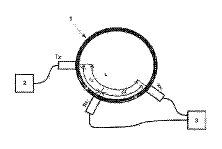
An apparatus and method for measuring the internal pressure of a pipe or
container is disclosed. The apparatus includes
an acoustical transmitter (Tx1) mounted on a wall (1) of said pipe or
container and a signal generator (2) connected to said
transmitter and which is adapted to provide a signal to the transmitter. The
signal from the transmitter is detected by two receivers
(Rx1, Rx2) mounted on said pipe or container in a distance from said
transmitter (Tx1). A processing unit (3) is connected to said
transmitter and receivers, the processing unit being adapted to measure the
travel time of an acoustical signal propagating between
two receivers in the wall (i) and determine the pressure inside the pipe or
container from said travel time.


French Abstract

L'invention concerne un appareil et un procédé de mesure de la pression interne d'un tuyau ou d'un récipient. L'appareil comprend un transmetteur acoustique (Tx1) monté sur une paroi (1) dudit tuyau ou récipient et un générateur de signal (2) connecté audit transmetteur et conçu pour fournir un signal au transmetteur. Le signal du transmetteur est détecté par deux récepteurs ((Rx1, Rx2) montés sur ledit tuyau ou récipient à une certaine distance dudit transmetteur (Tx1). Une unité de traitement (3) est connectée auxdits transmetteur et récepteurs, l'unité de traitement étant conçue pour mesurer le temps de propagation d'un signal acoustique se propageant entre deux récepteurs dans la paroi (1) et déterminer la pression à l'intérieur du tuyau ou du récipient à partir dudit temps de propagation.

Claims

Note: Claims are shown in the official language in which they were submitted.


6
The invention claimed is:
1. An apparatus for measuring the internal pressure of a pipe or container,
comprising:
an acoustical transmitter mounted on a wall of said pipe or container,
a signal generator connected to said transmitter and which is adapted to
provide a
signal to the transmitter,
a first receiver mounted on said pipe or container at a distance from the
transmitter,
a second receiver mounted on the pipe or container at a further distance from
the
transmitter,
a processing unit connected to said first and second receiver, the processing
unit
being adapted to measure the travel time of an acoustical signal propagating
from
the first to the second receiver in the wall and determine the pressure inside
the
pipe or container from said travel time.
2. An apparatus according to claim 1, wherein the processing unit is adapted
to
determine the pressure inside the pipe or container from the relation
<IMG>
where P is the pressure, .DELTA.L is the distance between the first receiver
and the
second receiver, t is the wall thickness, .DELTA.T is the travel time, and D
is the internal
diameter of the pipe or container.
3. An apparatus according to claim 1, wherein the signal generator is adapted
to
emit a signal exciting a thickness resonance frequency of said wall.
4. An apparatus according to claim 1, wherein the processing unit is adapted
to
determine the travel time by cross correlating a first signal received from
the first
receiver and a second signal received from the second receiver.
5. A method for measuring the pressure inside a pipe or container, the method
comprising steps of:
transmitting an acoustical signal from an acoustical transmitter mounted on a
wall
of said pipe or container,
receiving the acoustical signal at a first receiver mounted on said pipe or
container

7
at a distance from the transmitter,
receiving the acoustical signal at a second receiver mounted on the pipe or
container at a further distance from the transmitter,
measuring the travel time of the acoustical signal propagating from the first
to the
second receiver in the wall, and
determining the pressure inside the pipe or container from said travel time.
6. A method according to claim 5, wherein the pressure is determined from the
relation
<IMG>
where P is the pressure, .DELTA.L is the distance between the first receiver
and the
second receiver, t is the wall thickness, .DELTA.T is the travel time, and D
is the internal
diameter of the pipe or container.
7. A method according to claim 5, wherein the acoustical signal is exciting a
thickness resonance frequency of the wall.
8. A method according to claim 5, wherein the acoustical signal is a sinc wave
packet exciting at least one thickness resonance frequency of the wall.
9. A method according to claim 5, wherein the travel time is determined by
cross-
correlating signals received in said receivers.
10. A method according to claim 5, wherein the acoustic signal is a sound
pulse.
11. A method according to claim 10, wherein the acoustic signal is a burst
pulse of
a predefined number of periods.

Description

Note: Descriptions are shown in the official language in which they were submitted.


1
AN APPARATUS AND METHOD FOR MEASURING THE PRESSURE
INSIDE A PIPE OR CONTAINER
Field of the Invention
s
The present invention relates to an apparatus and method for measuring the
pressure inside a pipe or container.
Background
Offshore pipelines must be shut down regularly for maintenance purposes. A
maintenance period offshore involves a complete shut-down for typically 14
days.
During this period the pipe between offshore and onshore installations will be
shut
from both sides. Existing pressure sensors at both installations are
positioned
is outside the valves, and thus there are currently no way to monitor the
pressure
inside the closed pipe to detect a leakage during the shutdown period. It is
also
important to monitor and control gas pressure during the pipe shutdown process
due to the fact that high pressure differences cause wear of the valves, and
should
be minimized.
From US patent no. 3 977 252 there is known an apparatus for monitoring
the pressure of a liquid inside a pipeline. The pressure is monitored by
passing
regularly repeated pulses of ultrasonic waves from a transmitter through the
pipe
wall, liquid and opposite side of the pipe wall to a receiver. The pressure is
determined from the travel time of the pulses. Such an apparatus may find its
application in monitoring pressure inside liquid-filled pipes. However, in a
gas-filled
pipe, the large acoustical impedance contrast between the pipe wall and the
gas
inside means that only a small portion of the acoustical energy is transferred
through the gas. Most of the energy is transferred in the pipe wall directly
from the
transmitter to the receiver, the wall acting as a resonant waveguide for the
acoustic
energy. Pulses going the long path along the pipe wall will arrive earlier
than pulses
passing through the gas due to the large acoustic velocity in steel, and with
much
larger amplitude, it will completely mask the desired pulses that have passed
through the gas. Furthermore would it be impossible to use this method in a
multiple phase fluid or a mixture of fluids, as the velocity would differ
according to
which fluid or phase the waves pass through.
From WO 2014/004620 there is known a method for measuring the pressure
inside a vessel using ultrasonic means. An ultrasonic signal is transmitted
from a
transmitter mounted on the wall of the vessel and received by a receiver
mounted
Date Recue/Date Received 2020-04-16

2
on the wall in a distance from the transmitter. A control- or processing unit
is used
to find the travel time of the signal from the transmitter to the receiver,
and the
pressure is computed as a function of the travel time.
Thus, there is a need for a method for measuring the pressure inside a
s pipeline or other container without contacting the interior space of said
pipeline or
container, and that can be used to measure the pressure reliably even if there
should be a gas inside the pipeline or container, that is to provide reliable
pressure
data independently of which fluid or fluids are present inside the pipe or
container.
The method should provide a more accurate pressure reading than prior art
io methods.
It is an object of the present invention to provide an apparatus and method
solving said needs.
In particular the invention relates to an apparatus for measuring the internal
pressure of a pipe or container, the apparatus including in an acoustical
transmitter
is mounted on a wall of said pipe or container, a signal generator
connected to said
transmitter and which is adapted to provide a signal to the transmitter, a
first
receiver mounted on said pipe or container in a distance from the transmitter,
a
second receiver mounted on the pipe or container in a further distance from
the
transmitter, and a processing unit connected to said first and second
receiver, the
zo processing unit being adapted to measure the travel time of an
acoustical signal
propagating from the first to the second receiver in the wall and determine
the
pressure inside the pipe or container from said travel time.
The use of two receivers means that the travel time may be measured with
increased accuracy.
25 The processing unit is adapted to determine the pressure inside the pipe
or
container from the relation
2ALt
P cc¨
LTD
30 where P is the pressure, AL is the distance between the first receiver
and the
second receiver, t is the wall thickness, AT is the travel time, and D is the
internal
diameter of the pipe or container.
According to a preferred embodiment, the signal generator is adapted to
emit a signal exciting a thickness mode of said wall.
35 This will greatly increase the coupling between the transducers.
The processing unit may also be adapted to determine the travel time by
cross correlating the received signals.
Date Recue/Date Received 2020-04-16

3
The invention is intended to be used in noisy environments, and the use of
cross-correlation will increase the accuracy of the determination of the
travel time
between the receivers.
The invention also relates to a corresponding method for measuring the
s .. internal pressure of a pipe or container.
Brief description of the Drawing
The invention will now be described in reference to the appended drawing,
io Figure 1 which shows a preferred embodiment of an apparatus according to
the
invention.
Detailed Description
15 The invention is based on observing the behaviour of acoustic waves
travelling in the pipe/container wall, and not as in prior art, by observing
waves
travelling through the medium inside the pipe/container.
A pressure difference between the inside and outside of the pipe/container
will set up stress in the wall. For a cylindrical wall the stress a is given
by:
PD
a = t
Where P is the pressure difference, D is the internal diameter, and t is the
wall thickness.
There is a nearly linear relationship between wall stress and phase velocity.
Measuring phase velocity will provide a value of the wall stress from which
the
pressure difference over the wall may be deducted. Hence,
a c< v,
where I), is the phase velocity in the wall of the pipe or container.
Fig. 1 is a schematic illustration of the apparatus for measuring pressure
according to the invention. The inventive apparatus includes a signal
generator 2
driving a transmitter Txi mounted onto the wall 1 of a pipe or container.
The transmitted signal may be a sharp spike, a square wave, or a burst
pulse. The burst pulse may be a plain sine wave burst, a swept wave burst or a
sinc
burst pulse. It is preferred to use a burst pulse to avoid dispersion and to
ease the
detection in a noisy environment. It is further preferred to let the burst
pulse excite
one of the thickness resonance frequencies of the wall. There are several
thickness
Date Recue/Date Received 2020-04-16

4
resonance frequencies available, but here it is preferred to use the first
harmonic
(wavelength = t) due to the distance to other mode frequencies. The signal
will
propagate along the wall by several modes, notably as shear- and Lamb-waves.
The periodic signal is picked up by two receivers Rxi and Rx2. The received
s signals are digitized and fed to a processing unit 3. The processing unit
is adapted
to determine the time shift between the receivers. The time shift may be
determined by cross-correlating the signals from the receivers. Another option
is to
measure the time shift between identified zero-crossings in the signals, or
measure
when the signals exceed a specified threshold for determining the leading edge
of
io the first arrival.
A general description of the method will be as follows;
- A sound pulse is transmitted from an acoustic contact transducer
transmitter, Txi to a first acoustic transducer receiver, Rxi, and preferably
also to a
second acoustic contact transducer, Rx2 arranged on a pressure container or
pipe.
is The pulse can be a so-called "burst" pulse of a predefined number of
periods. It
could e.g. be between 1 and 20 periods, preferably 5-10 periods. The pulse can
typically have a centre frequency within the band from 50 kHz to 1000 kHz. The
pulse should be adapted to the thickness of said pressure container or pipe,
so that
a clear pulse is received at said receivers, Rxi and possibly also Rx2.
20 - The time lapse, ti, from said pulse is transmitted at Txi until it is
received
at the first receiver, Rxi, is measured using a suitable time detection
method, e.g.
a cross-correlation or zero-crossing detection method.
- The time lapse, T2, from said pulse is transmitted at Txi until it is
received
at the second receiver, Rx2, is measured using the same time detection method.
25 - The speed of sound through the wall of the container or pipe, vp, can
be
found through L1, the distance from Txi to Rxi, or, if two receivers are used,
the
distance between Rxi and Rx2, AL:
f AT E T2 ¨ Ti
12,., =¨ , where
' AT AL E L2 ¨ L1'
If only one receiver is used, the following equations apply:
T1 -- ,_L
TEL,
vp
Thereby:
V - L.,
P
Tl-TEL'
Date Recue/Date Received 2020-04-16

5
Where TEL represents the delay time of the electronics, that should be
accounted for.
It thereby follows that the method is equally suitable with the use of one or
two receivers.
s Now it follows that:
AL PD AL
o- oc ¨ , or ¨ oc ¨
AT 2t AT
so that:
n 261t
r cc¨.
ATE)
io By using a calibration procedure for a given container or pipe, it
should be
feasible to attain a pressure resolution of about 1 bar.
The transducers may be clamped to the pipe/container by any suitable
method, e.g. a strap around the pipe/container, or strong magnets, and may
include a suitable coupling gel to improve the acoustical coupling to the
is pipe/container.
The set-up shown includes one transmitter and two receivers. It is also
possible to use one transmitter and only one receiver measuring the time shift
for
the signal between the transmitter and receiver. However, it may be difficult
to
achieve a satisfactory accuracy with such a set-up. The method is equally
suitable
zo .. with lamb-waves and shear waves.
In Fig. 1 the transmitter and receivers are located along the circumference
of a pipe or container, but they could also be placed in the longitudinal
direction of
the pipe or container, or in any other possible direction.
Date Recue/Date Received 2020-04-16

Representative Drawing
A single figure which represents the drawing illustrating the invention.
Administrative Status

2024-08-01:As part of the Next Generation Patents (NGP) transition, the Canadian Patents Database (CPD) now contains a more detailed Event History, which replicates the Event Log of our new back-office solution.

Please note that "Inactive:" events refers to events no longer in use in our new back-office solution.

For a clearer understanding of the status of the application/patent presented on this page, the site Disclaimer , as well as the definitions for Patent , Event History , Maintenance Fee  and Payment History  should be consulted.

Event History

Description Date
Grant by Issuance 2020-12-22
Inactive: Cover page published 2020-12-21
Pre-grant 2020-11-09
Inactive: Final fee received 2020-11-09
Common Representative Appointed 2020-11-07
Notice of Allowance is Issued 2020-11-02
Letter Sent 2020-11-02
Notice of Allowance is Issued 2020-11-02
Inactive: QS passed 2020-10-30
Inactive: Approved for allowance (AFA) 2020-10-30
Inactive: COVID 19 - Deadline extended 2020-08-19
Inactive: COVID 19 - Deadline extended 2020-08-06
Inactive: COVID 19 - Deadline extended 2020-07-16
Inactive: COVID 19 - Deadline extended 2020-07-02
Inactive: COVID 19 - Deadline extended 2020-06-10
Inactive: COVID 19 - Deadline extended 2020-05-28
Inactive: COVID 19 - Deadline extended 2020-05-14
Inactive: COVID 19 - Deadline extended 2020-04-28
Amendment Received - Voluntary Amendment 2020-04-16
Inactive: COVID 19 - Deadline extended 2020-03-29
Examiner's Report 2019-12-30
Inactive: Report - No QC 2019-12-24
Letter Sent 2019-12-06
Request for Examination Requirements Determined Compliant 2019-12-04
Request for Examination Received 2019-12-04
Amendment Received - Voluntary Amendment 2019-12-04
Advanced Examination Determined Compliant - PPH 2019-12-04
Advanced Examination Requested - PPH 2019-12-04
All Requirements for Examination Determined Compliant 2019-12-04
Common Representative Appointed 2019-10-30
Inactive: Delete abandonment 2017-06-05
Inactive: Abandoned - No reply to s.37 Rules requisition 2017-02-23
Inactive: Cover page published 2016-12-15
Inactive: Reply to s.37 Rules - PCT 2016-12-02
Inactive: Notice - National entry - No RFE 2016-11-25
Inactive: First IPC assigned 2016-11-25
Inactive: IPC assigned 2016-11-23
Inactive: Request under s.37 Rules - PCT 2016-11-23
Application Received - PCT 2016-11-23
National Entry Requirements Determined Compliant 2016-11-14
Application Published (Open to Public Inspection) 2015-11-19

Abandonment History

There is no abandonment history.

Maintenance Fee

The last payment was received on 2020-01-17

Note : If the full payment has not been received on or before the date indicated, a further fee may be required which may be one of the following

  • the reinstatement fee;
  • the late payment fee; or
  • additional fee to reverse deemed expiry.

Patent fees are adjusted on the 1st of January every year. The amounts above are the current amounts if received by December 31 of the current year.
Please refer to the CIPO Patent Fees web page to see all current fee amounts.

Fee History

Fee Type Anniversary Year Due Date Paid Date
Basic national fee - standard 2016-11-14
MF (application, 2nd anniv.) - standard 02 2017-05-12 2017-01-04
MF (application, 3rd anniv.) - standard 03 2018-05-14 2018-01-09
MF (application, 4th anniv.) - standard 04 2019-05-13 2019-01-11
Request for examination - standard 2020-05-12 2019-12-04
MF (application, 5th anniv.) - standard 05 2020-05-12 2020-01-17
Final fee - standard 2021-03-02 2020-11-09
MF (patent, 6th anniv.) - standard 2021-05-12 2021-01-28
MF (patent, 7th anniv.) - standard 2022-05-12 2022-05-11
MF (patent, 8th anniv.) - standard 2023-05-12 2023-05-05
MF (patent, 9th anniv.) - standard 2024-05-13 2024-05-08
Owners on Record

Note: Records showing the ownership history in alphabetical order.

Current Owners on Record
HALFWAVE AS
Past Owners on Record
PETTER NORLI
Past Owners that do not appear in the "Owners on Record" listing will appear in other documentation within the application.
Documents

To view selected files, please enter reCAPTCHA code :


To view images, click a link in the Document Description column (Temporarily unavailable). To download the documents, select one or more checkboxes in the first column and then click the "Download Selected in PDF format (Zip Archive)" or the "Download Selected as Single PDF" button.

List of published and non-published patent-specific documents on the CPD .

If you have any difficulty accessing content, you can call the Client Service Centre at 1-866-997-1936 or send them an e-mail at CIPO Client Service Centre.

({010=All Documents, 020=As Filed, 030=As Open to Public Inspection, 040=At Issuance, 050=Examination, 060=Incoming Correspondence, 070=Miscellaneous, 080=Outgoing Correspondence, 090=Payment})


Document
Description 
Date
(yyyy-mm-dd) 
Number of pages   Size of Image (KB) 
Claims 2016-11-13 2 71
Abstract 2016-11-13 1 68
Representative drawing 2016-11-13 1 34
Drawings 2016-11-13 1 34
Description 2016-11-13 5 305
Claims 2019-12-03 2 63
Description 2020-04-15 5 223
Claims 2020-04-15 2 68
Representative drawing 2020-11-25 1 23
Maintenance fee payment 2024-05-07 5 193
Notice of National Entry 2016-11-24 1 192
Courtesy - Acknowledgement of Request for Examination 2019-12-05 1 433
Commissioner's Notice - Application Found Allowable 2020-11-01 1 549
International Preliminary Report on Patentability 2016-11-13 9 371
National entry request 2016-11-13 4 112
International search report 2016-11-13 2 53
Response to section 37 2016-12-01 3 93
Request under Section 37 2016-11-22 1 48
Courtesy - Office Letter 2017-06-04 1 39
Request for examination / PPH request / Amendment 2019-12-03 9 299
Examiner requisition 2019-12-29 3 167
Amendment 2020-04-15 12 412
Final fee 2020-11-08 5 103
Maintenance fee payment 2021-01-27 1 26
Maintenance fee payment 2022-05-10 1 26