Note: Descriptions are shown in the official language in which they were submitted.
CA 02949299 2016-11-16
WO 2015/177274 PCT/EP2015/061243
1
Key system to ensure correct use of inserts
The present invention relates to an oil filtration system.
It has been known for several years to use oil for lubricating the movable
parts in vari-
ous types of machinery. Similarly, it has been known that the oil gets
contaminated af-
ter having been used for some time. Thus, it is advantageous to filter the oil
e.g. to
avoid breakdown of the machinery, to prolong the lifetime of the various
components
and to reduce the expenses for maintenance. One type of oil filtration units
comprises
an outer shell in which an oil filter is inserted. Typical systems used for
mounting the oil
filters in the outer shell comprises rubber sealings assisted by applying a
sealing pres-
sure by either springs or tightening of bolts etc. Normally, these mounting
systems do
not have a specific function directed towards assuring that the wrong insert
does not
get mounted, which means that there is a considerable risk that a wrong type
of insert
can be mounted in an oil filtration unit which may increase the risk of a
breakdown of
machinery due to an incorrect oil filtration scheme.
To remedy the above disadvantage, various modifications and variants of oil
filtration
systems have been proposed. Examples include US 2006/0162305 Al which relates
to
a key system for filters and their connecting heads, brackets or other
holders. The filter
cartridge and its holder each has a keyed surface, one being a protruding
keyed sur-
face, one being a protruding key and one being a recessed lock. Cooperation of
these
keyed surfaces is required in order for the filter cartridge to be installed
in the holder, so
that mismatched cartridges cannot be installed into the holder, for example,
to prevent
a particular type of cartridge from being placed in a filtration or other
process where it
would be inappropriate, or undesired. The keyed surfaces are selectively
locatable
preferably at different circumferential locations on a perimeter of the
head/holder. The
perimeter may be, for example, on an outer shoulder surface of a filter and an
inner
surface of a valve head, or on outer and inner surfaces of connectors that
provide a
liquid seal between the filter and the head/holder.
Known oil filtration systems, which include a mounting system ensuring that
the wrong
oil filter does not get installed, are complicated and expensive to
manufacture.
It is a first aspect of the present invention to provide an oil filtration
system which is
simple and inexpensive.
CA 02949299 2016-11-16
WO 2015/177274 PCT/EP2015/061243
2
It is a second aspect of the present invention to provide an oil filtration
system which
ensures correct insertion of the correct type of filter in a given oil
filtration unit.
It is a third aspect of the present invention to provide an oil filtration
system which uses
a simple procedure for installing and replacing filters.
It is a fourth aspect of the present invention to provide an oil filtration
system which
eliminates the risk of leakage.
It is a fifth aspect of the present invention to provide an alternative to the
oil filtration
systems of the kind mentioned in the opening paragraph.
The novel and unique way in which these and other aspects are achieved
according to
the present invention is the fact that the oil filtration system comprises:
¨ an oil filtration unit,
¨ an oil filter having a central opening extending along a central axis of
the oil filter,
¨ the oil filtration unit being provided with at least one first physical
struc-
ture having a first cross-sectional shape and a predefined longitudinal
length in relation to a central axis of the oil filtration unit,
¨ the oil filter being provided with at least one second physical structure
having a second cross sectional shape and a predefined longitudinal
length in relation to the central axis of the oil filter and
¨ an inner or outer periphery of the second physical structure being ar-
ranged to mate with the outer or inner periphery of the first physical
structure allowing the oil filter to reach its correct insertion position in
the oil filtration unit
- where at least one of the end surfaces of the oil filter relative to the
central axis of the oil filter comprises the at least one second physical
structure.
In accordance with the invention, there is further provided an oil filtration
system
comprising:
¨ an oil filtration unit having a central projection extending along a central
axis of the oil filtration unit,
CA 02949299 2016-11-16
WO 2015/177274 PCT/EP2015/061243
3
¨ an
oil filter having a central opening extending along a central axis of
the oil filter, where the central opening of the oil filter is adapted to be
introduced onto the central projection of the oil filtration unit in the di-
rection of the central axis of the oil filtration unit,
¨ the oil
filtration unit being provided with at least one first physical struc-
ture having a first cross-sectional shape and a predefined longitudinal
length in relation to the central axis of the oil filtration unit,
¨ the oil filter being provided with at least one second physical structure
having a second cross sectional shape and a predefined longitudinal
length in relation to the central axis of the oil filter and
¨ an inner or outer periphery of the second physical structure being ar-
ranged to mate with the outer or inner periphery of the first physical
structure allowing the oil filter to reach its correct insertion position in
the oil filtration unit,
¨ where at least
one of the end surfaces of the oil filter relative to the
central axis of the oil filter comprises the at least one second physical
structure.
Typically, the oil filters used in oil filtration units can be made with
substantially similar
geometry, i.e. the exterior shape, but when it comes to the purpose, physical
character-
istics, properties and function of the oil filters, the filters may be very
different from each
other. For this reason, it is a risk that an oil filter with the wrong
properties is installed in
an oil filtration unit. Installation of the wrong type of filter, in terms of
function and/or
quality, may lead to a detrimental reduction in the expected life-time of the
system
which utilises the oil and the function and/or lifetime of the filter.
Thus, the provision of an oil filtration system with at least one first and
one second
physical structure, where an inner or outer periphery of the second physical
structure is
arranged to mate with the outer or inner periphery of the first physical
structure, allows
the correct type of oil filter to reach its correct installation position in
the oil filtration unit.
At correct installation and thus at the operational position of the filter,
the at least first
and second physical structures thus engage each other. For this reason, the
user of
the oil filtration unit can be assured that only filters with a physical
structure, which
matches in peripheral shape with the peripheral shape of the physical
structure of the
oil filtration unit, is installed. This requirement prevents the wrong type of
filter from
reaching the correct insertion position in the oil filtration unit and thus
from being in-
CA 02949299 2016-11-16
WO 2015/177274 PCT/EP2015/061243
4
stalled in the oil filtration unit. Thus, correct insertion of the correct
type of filter in a giv-
en oil filtration unit is ensured.
The oil filtration system can thus be understood as comprising a key system
for mount-
ing an oil filter in an oil filtration unit, where the key system comprises at
least one key
assembly comprising:
- a key with an outer cross-sectional shape, and
- a keyhole with an inner cross-sectional shape,
wherein the inner periphery of the cross-sectional shape of the keyhole is
similar in
shape and size to the outer periphery of the cross-sectional shape of the key.
This
would be the situation if the oil filter had a keyhole that had to fit to a
key provided in re-
lation to the oil filtration unit in order for the filter to be installed
correctly in the oil filtra-
tion unit. At correct installation, the keyhole can thus be understood as
encircling or
surrounding the key.
Having an end surface of the oil filter comprise the at least one second
physical struc-
ture has the advantage that the second physical structure may form part of the
filter
e.g. by comprising a similar material and as such be an active component in
the filter-
ing process. Alternatively, if the second physical structure was arranged on
the oil filter,
e.g. on an end surface of the oil filter, but did not comprise a material
suitable for oil fil-
tration, the second physical structure would take up space and thus influence
the filter-
ing capacity of the oil filter.
Provided that at least one end of the end surfaces of the oil filter comprises
the at least
one second physical structure, easy disposal of the oil filter is facilitated.
Thus, in case
the at least one second physical structure comprises the same material as the
oil filter,
there is no need for arranging a disposal process for the at least one second
physical
structure different from the disposal process for the oil filter. In case the
oil filter and the
second physical structure may comprise a natural or synthetic polymer such as
cellu-
lose, they may e.g. be disposed of by incineration.
Mounting the at least one second physical structure on one or both end
surfaces of the
oil filter facilitates easy installation of the at least one second physical
structure on the
oil filter, both in the case where the at least one second physical structure
is mounted
during production of the oil filter, and in the case where it is mounted after
the produc-
tion of the oil filter. The reason is that the user thus has full visual
contact with the at
CA 02949299 2016-11-16
WO 2015/177274 PCT/EP2015/061243
least one second physical structure and has a higher rate of success in
mounting the
oil filter correctly.
In an embodiment, the oil filtration unit can have a projection extending in
the direction
5 of the central axis of the oil filtration unit. Said projection may
comprise the at least one
first physical structure and may be arranged either along the central axis of
the oil filtra-
tion unit or away from said central axis.
In one embodiment, the central projection of the oil filtration unit can
comprise the at
least one first physical structure, the central projection preferably being a
stay bolt. A
stay bolt can thus be an extension of the central projection of the oil
filtration unit. In-
stalling a stay bolt in an oil filtration unit ensures a more stable and easy
installation of
the oil filter in the oil filtration unit. Furthermore, the stay bolt can
facilitate installation of
more than one physical structure along the center axis.
When inserting a filter in an oil filtration unit, a central projection, such
as a stay bolt,
functions as a guiding element for the user when installing the filter.
Basically, the user
only has to apply the central opening of the filter on the open end of the
central projec-
tion and then slide the filter towards the bottom (or top) of the oil
filtration unit, and final-
ly rotate the filter until the first and second physical structures are
aligned and engage
each other. This way, the user does not have to worry about joining the first
and sec-
ond physical structures before rotating the oil filter until they engage each
other which
can be difficult due to low visibility inside the oil filtration unit after
inserting the oil filter.
Thus, a simple procedure of installing and replacing filters is provided.
Moreover, the production of the first physical structure is easy as it can be
turned on a
turning lathe or cast together with the stay bolt. Furthermore, if the
physical structure is
broken some time or if the function of the oil filtration unit changes, the
physical struc-
ture can thus easily be replaced.
In one embodiment, an end surface of the oil filtration unit can comprise the
at least
one first physical structure.
Within the scope of the present invention, an "oil filtration unit" can have
the shape of a
substantially cylindrical container. In general, the oil filtration unit can
comprise two
parts ¨ a first part and a second part. The first part consists of one end
surface and the
CA 02949299 2016-11-16
WO 2015/177274 PCT/EP2015/061243
6
side surface of the substantially cylindrical container. Typically, the first
part can be
connected to the apparatus containing the oil which has to be filtered by the
oil filtration
unit. The second part can consist of the other end surface, and can be
understood to
function as a lid, and is thus typically only connected to said apparatus by
way of its at-
tachment with the first part. Thus, within the scope of the present invention,
but not lim-
ited to, the term "end surface" can comprise the inner surface of the first
part of the oil
filtration unit or the inner surface of the second part of the oil filtration
unit. Furthermore,
said inner end surface may be a separate disc which may be inserted into an
existing
oil filtration unit comprising side walls and an inner end surface or be
connected to the
side walls of an oil filtration unit and thus constitute the end surface of
the oil filtration
unit, or be produced together with the side walls of the oil filtration unit
as one unit.
Other shapes and sizes of the oil filtration unit are also intended to be
included in the
present invention. For instance, the oil filtration unit could, but is not
limited to, consist
of two substantially symmetrical parts, both comprising an end and side
surfaces, or
the oil filtration unit could have the shape of a substantially cubic
container.
The first physical structure can be produced as part of the end surface of the
oil filtra-
tion unit during the initial production of the oil filtration unit as the risk
of an unintention-
al change of the type of filters suitable for use in the oil filtration unit
can thus be con-
siderably reduced, or at best eliminated. If produced as part of the end
surface, the first
physical structure cannot simply be removed, e.g. by rotation or pressure. The
user has
to e.g. saw or cut it off. Thus, it has to be the intention of the user to
deliberately re-
move the first structure with the risk of destroying the whole oil filtration
unit.
Mounting the first physical structure at said end surface can involve either
mounting it
permanently, e.g. by use of welding, or mounting it with the possibility of
removing it
again, e.g. by use of a threaded installation in both the first physical
structure and the
end surface. When mounting the first physical structure permanently, the
advantages
stated in the above paragraph apply. When mounting the first physical
structure tempo-
rarily, the user has the advantage that the first physical structure can
easily be replaced
either if broken or if the function of the oil filtration unit has changed so
that another
type of oil filter has to be used. It applies to both ways of mounting the
first physical
structure that it can be mounted in both new and already existing oil
filtration units. Fur-
thermore, no matter if the first physical structure has been mounted on or
produced as
a part of the end surface, placing the first physical structure at this
position results in
easy installation of both the first physical structure, i.e. just install it
at the end surface,
CA 02949299 2016-11-16
WO 2015/177274 PCT/EP2015/061243
7
and of the filter, i.e. the user always knows that the first physical
structure is placed at
the end surface, so there is no need to investigate further.
Depending on how the end surface is defined in relation to the sides of the
oil filtration
unit, the first physical structure in one embodiment may also be mounted on or
pro-
duced as part of the end surface which is not connected to the apparatus
containing
the oil which has to be filtered by the oil filtration unit, i.e. the end
surface can constitute
the lid. If the first physical structure has not been installed in the oil
filtration unit from
the start, it can thus more easily be installed in the end surface not
connected to the
apparatus as said end surface can be moved to a location suitable for
performing the
installation, e.g. a workshop.
In one embodiment, the at least one second physical structure can be located
at any
position along the central axis of the oil filter. Placing the second physical
structure
along the central axis of the oil filter means that the complexity of the
formation of the
oil filter is reduced as no difficult and precise measurement and alignment is
required in
order to make the second physical structure. It merely has to be placed along
the cen-
tral axis of the oil filter. Furthermore, the embodiment is advantageous in
that more
ways of varying the different types of filter exists as the position of the
second physical
structure is not limited to e.g. the ends of the oil filter, which means that
the oil filter
types can vary in regard to the position of the second physical structure
along the cen-
tral axis. Moreover, more than one second physical structure can thus be
placed in the
oil filter, e.g. one second physical structure at the one end of the oil
filter and another
second physical structure at the other end of the oil filter.
In one embodiment of the present invention, a planar structure, which is
adapted to be
mounted on at least one of the end surfaces of the oil filter, can comprise
the at least
one second physical structure. Producing the at least one second physical
structure as
part of a planar structure has the advantage that the user of the oil filter
does not have
to consider how to implement the at least one second physical structure in the
produc-
tion of the oil filter. The production of the planar structure can be part of
a completely
different production facility if wanted. Thus, the user can continue to use
the same pro-
duction facilities and tools, and does not have to amend an already
functioning produc-
tion facility.
CA 02949299 2016-11-16
WO 2015/177274 PCT/EP2015/061243
8
A further advantage of producing the at least one second physical structure as
part of a
planar structure is that in case the user wants to change the function of the
oil filtration
unit so that a different type of oil filter is to be used, the production
facility and tem-
plates for the new type of oil filter does not have to be amended according to
the spe-
cific physical structure used on the oil filtration unit. Only the production
of the planar
structure has to be amended.
In one embodiment, at least a first set of first and second physical
structures and a
second set of first and second physical structures can be provided, and the
first and
second sets can be angled axially in relation to each other. Having a first
and a second
physical structure in the oil filtration unit facilitates that only a correct
type of filter can
be installed into the oil filtration unit. However, making use of only one
such set of first
and second physical structures could possibly be insufficient in some cases to
avoid
installation of the wrong type of filter. After being operated for a long
time, the first
physical structure could be at risk of being worn out of shape which could
result in that
another type of filter could fit into place. Furthermore, making use of only
one set could
in some cases open up for a deliberate amendment of the first physical
structure and
thus the type of filter used. Instead, making use of at least a first and a
second set of
physical structures minimises the above-mentioned risks of wrong use of the
oil filtra-
tion unit as not only one set of physical structures, but two or more have to
be worn out
of shape or amended. A further advantage is that having not only one set of
physical
structures, but two or more increase the number of different types of oil
filters that can
be designed.
Advantageously, the first and second sets can be angled axially in relation to
each oth-
er. Thus, the cross-sectional shapes of the first and the second sets of
physical struc-
tures do not have to be different from each other, but merely have to be
angled in rela-
tion to each other thus avoiding a wrong installation of the oil filter, e.g.
avoid turning
the oil filter up-side down.
Said first and second sets of physical structures may be arranged along the
outer pe-
riphery of the oil filter so that the user may visually see said physical
structures when
inserting the oil filter in the oil filtration unit which facilitates easy and
correct insertion
of the oil filter. In case the oil filter has a substantially cylindrical
shape, arranging said
first and second sets along the outer periphery results in that said first and
second sets
are angled axially relative to each other.
CA 02949299 2016-11-16
WO 2015/177274 PCT/EP2015/061243
9
In one embodiment, a first physical structure can be arranged at the central
projection
of the oil filtration unit, and at least one first physical structure may not
be arranged at
the central projection of the oil filtration unit, and corresponding second
physical struc-
tures can be provided at the oil filter. As previously explained, the
embodiment has the
advantage compared to oil filtration systems comprising only one first and one
corre-
sponding second physical structure that the risk of the first physical
structure being
worn out of shape after use for a long time could result in another type of
filter being
able to fit into place, obviously depending on the specific shape.
Furthermore, making
use of only one first and second physical structure could in some cases open
up for a
deliberate amendment of the first physical structure and thus the type of
filter used. In-
stead, making use of more than one first and second physical structure
minimises the
above-mentioned risks of wrong use of the oil filtration unit as not only one
set of first
physical structure, but two or more have to be worn out of shape or amended.
Similar-
ly, having not only one first and second physical structure, but two or more
increases
the number of different types of oil filtration units that can be designed
with each their
specific type of filter.
One example of implementation of the present embodiment could be a case in
which a
first physical structure is arranged at the central projection, and three
first physical
structures are placed symmetrically across the central axis of the oil
filtration unit. Cor-
responding second physical structures are placed at the oil filter, e.g.
mounted on or
produced as a part of one of the end surfaces of the oil filter relative to
the central axis
of the oil filter, or alternatively, produced as part of a planar structure
which is adapted
to be mounted on at least one of the end surfaces of the oil filter.
The disclosed combinations have the technical production advantage that a very
large
number of various physical structure combinations can be produced solely by
use of
one standard cross-sectional shape. In other words, all oil filtering units
can be pro-
duced purely on the basis of the same parts/components taken from the shelf in
a stor-
age. The fitting takes place by use of a template that shapes the physical
structures of
the oil filtering unit to the correct oil filter. The shaping takes place by
forming, e.g. turn-
ing, the first physical structure to the correct shape by use of a
master/template. The
shaping in the oil filters can take place either as part of the end of the
production, i.e.
during assembling of the oil filter, or during casting of the oil filter by
use of specially
designed tools for casting which can be adjusted/configured to make different
physical
CA 02949299 2016-11-16
WO 2015/177274 PCT/EP2015/061243
structure combinations by use of adjustable masters/templates. Thus, the
physical
structures are easy to produce and cheap to manufacture.
It is foreseen within the present invention that the oil filtration unit may
not comprise a
5 central projection, but that the at least one first physical structure is
arranged along the
central axis of the oil filtration unit.
In one embodiment, the cross-sectional shapes of the at least one first and
second
physical structure can be non-circular across the central axis of the oil
filtration unit.
10 This is an advantage as making use of a circular shape across the
central axis of the
oil filtration unit would increase the risk of deliberate misuse of the oil
filtration system
or the risk of unintentional misuse of the oil filtration system due to wear,
at least in the
case where only one first and one second physical structure are applied.
However, it is
obviously within the scope of the present invention to make use of
substantially circular
shapes such as oval shapes.
In one embodiment, the oil filtration system can comprise sealing between the
oil filtra-
tion unit and the oil filter so as to prevent oil-to-be-filtered (influent)
from bypassing the
oil filter and flowing directly to the outlet tube of the oil filtration unit.
The sealing may
be formed between the material of the oil filter and the material of the oil
filtration unit,
such as between a surface of the oil filter and of the oil filtration unit,
respectively.
When providing that at least one of the end surfaces of the oil filter
relative to the cen-
tral axis of the oil filter comprises the at least one second physical
structure, sealing
may be formed by the close fit between the first and second physical
structures and
thus be formed between the material of the oil filter, such as cellulose, and
the material
of the first physical structure, such as metal. Therefore, sealing may be
provided with-
out use of additional sealing means such as 0-rings or other mechanical
elements.
In one embodiment, the at least one first and/or second physical structure can
com-
prise a sealing means arranged between the at least one first and second
physical
structure. After installation of the oil filter in the oil filtration unit,
the only parts of the oil
filtration system, which are not fixedly attached to each other, are the at
least one first
and second physical structure. Thus, there is a risk of dirty unfiltered oil
bypass-
ing/leaking into the cleaned/filtered oil without passing through the oil
filter ¨ from influ-
ent to effluent. Obviously, this is not wanted. Thus, it is an advantage to
arrange a seal-
ing between the at least one first and second physical structure to minimise
or at best
CA 02949299 2016-11-16
WO 2015/177274 PCT/EP2015/061243
11
to eliminate any leakage as minimising or eliminating leakage would result in
a better
and more efficient oil filtration. Special means can be inserted, formed or
shaped be-
tween the at least one first and second physical structure to make up for the
sealing, or
sealing can take place only between the at least one first and second physical
struc-
ture. Thus, a sufficient sealing would exist between close-fitted first and
second physi-
cal structures, e.g. in the case where the first physical structure is formed
in a metal
and the second physical structure is produced as part of an end surface of the
oil filter,
e.g. in a cellulose material. Thus, a simple and low-cost oil filtration
system is provided.
In an embodiment, the at least one first and/or second physical structure can
comprise
at least part of a sealing means arranged between the oil filtration unit and
the oil filter.
Thus, a sealing means may be arranged between both the at least one first
and/or
second physical structure and between another part of the oil filtration unit
and of the
oil filter, such as a surface, so as to provide an extra sealing means and
thus an extra
guaranty for preventing oil-to-be-filtered from bypassing the oil filter.
In one embodiment, where a first physical structure can be arranged at the
central pro-
jection of the oil filtration unit, and at least one first physical structure
may not be ar-
ranged at the central projection of the oil filtration unit, and corresponding
second phys-
ical structures can be provided at the oil filter, the sealing means can be
arranged be-
tween only the first physical structure, which is arranged at the central
projection of the
oil filtration unit, and the corresponding second physical structure. The
remainder at
least one first physical structure and corresponding second physical structure
can thus
be provided without any sealing means if they do not provide a possible
passageway
for the oil to be filtered from the outside of the oil filter to the inside
opening of the oil
filter and thus to the outlet part of the oil filtration unit. However, it is
obviously foreseen
by the present invention that the sealing can be arranged between one of the
remain-
der at least one first physical structure and corresponding second physical
structures or
between several of the first and second physical structures.
In one embodiment of the present invention, the sealing means can comprise a
sealing
ring arranged at an outer surface of the at least one first physical structure
or at an in-
ner surface of the at least one second physical structure. Advantageously, the
shape of
the sealing ring is made similar to the cross-sectional shape of the physical
structure,
so that sufficient and effective fitting can be made on either an outer
surface of the at
least one first physical structure or at an inner surface of the at least one
second physi-
CA 02949299 2016-11-16
WO 2015/177274 PCT/EP2015/061243
12
cal structure, or vice versa. Sealing rings have been known as sealing means
for sev-
eral years. They provide good and efficient sealing and can obviously be cheap
de-
pending on the material.
Optionally, the sealing means may not include a sealing ring.
In an embodiment, the sealing and/or sealing means can comprise an elevation.
The
elevation may be arranged either on the oil filter or on the oil filtration
unit. Thus, the el-
evation may be arranged on the oil filtration unit and contact the oil filter,
when the oil
filter has been inserted in the oil filtration unit.
In one embodiment, the sealing and/or sealing means can comprise an elevation
along
the inner surface of the at least one second physical structure, the elevation
preferably
being a lip ring. Applying an elevation as sealing means has the advantage
that the us-
er thus does not have to worry about e.g. controlling whether the sealing ring
is suffi-
ciently new, intact and correctly placed when inserting a new oil filter. The
sealing is al-
ready in place.
In an embodiment, the elevation can be arranged at an inner end surface of the
oil fil-
tration unit. Thus, when inserting the oil filter in the oil filtration unit,
the oil filter may
thus come into contact with the elevation. The elevation may form a closed
path around
an oil outlet part of the oil filtration unit (e.g. the outlet tube or the
opening of the inner
end surface) and/or around the central opening of the oil filter when it has
been in-
stalled in the oil filtration unit. When the oil filter has been inserted in
the oil filtration
unit, the elevation may thus protrude or cut into the oil filter, at least
partly. The width of
the elevation may decrease with increasing distance from the inner end surface
of the
oil filtration unit such as an edge of a knife so as to facilitate the ability
of the elevation
to protrude or cut into the oil filter so that sealing is provided between the
oil filter and
the oil filtration unit.
The elevation may be arranged at an inner end surface of the oil filtration
unit with a
form substantially similar to the outer periphery of the cross-sectional shape
of the oil
filter, but have a width/diameter slightly smaller than said outer periphery.
For this rea-
son, the elevation may protrude or cut into the oil filter near the edge of
the oil filter rel-
ative to the longitudinal axis of the oil filter. Thus, maximal use of the oil
filter is provid-
ed as the oil to be filtered cannot bypass part of the oil filter by choosing
a shorter flow
CA 02949299 2016-11-16
WO 2015/177274 PCT/EP2015/061243
13
path through the oil filter. A bypass of part of the oil filter would result
in said part of the
oil filter not being used fully for filtering oil.
In an embodiment, the sealing and/or sealing means can comprise any natural or
syn-
thetic polymer, and/or the oil filter and/or the at least one second physical
structure can
comprise any natural or synthetic polymer. The applicant has gained the
knowledge
that natural or synthetic polymer can cover the scope of the materials which
can advan-
tageously be applied for producing the sealing means and/or the at least one
second
physical structure, e.g. materials such as cellulose and polypropylene POM.
Natural or
synthetic polymer are cheap to produce and efficient to use e.g. in terms of
sealing and
manufacturing.
In one embodiment, the oil filter and/or the at least one second physical
structure can
comprise cellulose material. The term oil filter is to be understood so as to
include all
types and shapes of oil filter used in the technical field of the invention.
Advantageous-
ly, the oil filter can comprise a cellulose material as the applicant has
acquired the
knowledge that oil filters comprising cellulose material provide a reliable,
sufficient and
less expensive material that is easy to work with. Other materials suitable
for oil filtra-
tion are, however, foreseen within the scope of the present invention.
In one embodiment, the predefined longitudinal length of the at least one
first physical
structure and/or of the at least one second physical structure can be larger
than the
width of the sealing means. When using oil filters in oil filtration systems
for filtering oil,
it is known that the oil filter can shrink with time if the oil filter
comprises e.g. cellulose,
which is an organic material, and is put under a high pressure difference
between the
influent and effluent side of the oil filter. As the at least one first and
second physical
structure are not fixedly attached, they will move relative to each other in
the longitudi-
nal direction (central axis), when the oil filter shrinks. Thus, it is an
advantage that the
at least one first and second physical structure can move relative to each
other without
risking that the sealing is lost. Preferably, the predefined longitudinal
lengths of the at
least one first and second physical structure are thus sufficiently larger
than the width
of the sealing means. Thus, the risk of leakage is eliminated.
In one embodiment, the at least one first physical structure comprises an
opening ex-
tending along the longitudinal axis of the first physical structure thus
facilitating outlet of
the filtered oil from the central opening of the oil filter as this reduces
the complexity of
CA 02949299 2016-11-16
WO 2015/177274 PCT/EP2015/061243
14
the setup of the oil filtration system. Alternatively, the end surface of the
oil filtration unit
may comprise an opening extending along the central axis of the oil filter.
The structure and function of the oil filtration system will be described in
more detail be-
low with references to exemplary embodiments shown in the drawings wherein,
Fig. 1 shows a cross section of one embodiment of the oil filtration system,
seen in a
side view.
Fig. 2 shows an exploded view of an embodiment with one first and one second
physi-
cal structure.
Fig. 3 shows a cross-sectional view of a second physical structure.
Fig. 4 shows an exploded view of an embodiment with two first and second
physical
structures.
Figs. 5a and 5b show an exploded view of an embodiment with several first and
sec-
ond physical structures, seen from both ends.
Figs. 6a and 6b show an exploded view of an embodiment with several first and
sec-
ond physical structures, both shown in a perspective view.
Fig. 7 shows a cut-out of the exploded view of Fig. 6a.
Figs. 8a and 8b show an exploded view of an embodiment with several first and
sec-
ond physical structures, both shown in a perspective view.
In the figures, the oil filtration unit and oil filter are shown having a
cylindrical shape.
However, it should be understood that other shapes, such as cubic, many-sided,
and
other shapes that may be envisioned by the person skilled in the art may also
be within
the scope of the present invention.
Fig. 1 shows a cross section of one embodiment of the oil filtration system 1,
seen in a
side view. The oil filtration unit 2 comprises two parts, a first part 3 and a
second part 4.
The first part 3 may be seen as the body and the second part 4 as the lid of
the oil fil-
CA 02949299 2016-11-16
WO 2015/177274 PCT/EP2015/061243
tration unit 2. In the exemplary embodiment shown in Fig. 1, the oil
filtration unit 2 has
a cylindrical shape, and the first part 3 comprises an inner end surface 5 and
an inner
side surface 6 defining an inner opening 7. The inner end surface 5 may
comprise a
central projection 8 extending along a central axis A of the oil filtration
unit 2. The sec-
5 ond part 4 comprises an inner end surface 9 (not shown) with slightly
bent edges 10.
The first part 3 is connected to an inlet tube 11 providing an inlet flow of
oil to be filtered
(indicated by arrow) and to an outlet tube 12 providing an outlet flow of
filtered oil (indi-
cated by the arrow). Thus, the first part 3 is connected to the apparatus (not
shown)
containing the oil which is to be filtered by the oil filtration unit 2. The
second part 4
10 may be connected to said apparatus through its connection to the first
part 3. Thus, af-
ter installation of an oil filter 13 into the inner opening 7 of the oil
filtration unit 2, the first
3 and second part 4 are connected to each other and sealed by use of a sealing
means
arranged in a rim 14, so that oil cannot leak out of the oil filtration unit
2.
15 In the exemplary embodiment shown in Fig. 1, the oil filter 13 has been
inserted into
the oil filtration unit 2. The oil filter 13 may have a central opening 15
extending along a
central axis B of the oil filter 13 which is in this case converging with
central axis A of
the oil filtration unit 2. At the open ends of the oil filter 13, a first 16
and a second planar
structure 17 have been fixedly attached to the oil filter 13 by a liquid
and/or hermetically
tight attachment, e.g. by use of an adhesive. Other attachment means such as
screws,
welding, friction fitting, may also be foreseen within the present invention.
A first physi-
cal structure 18 is provided in continuation of the central projection 8 of
the inner end
surface 5 and is mounted to a stay bolt 19 or may alternatively be integrated
with the
stay bolt 19. The stay bolt 19 may have a substantially cylindrical cross-
sectional shape
in the radial direction of the oil filtration unit 2 and may extend the whole
length of the
oil filter 13 thus extending out of the oil filtration unit 2 or alternatively
into a cavity of
the second part 4 of the oil filtration unit 2, where the second part
increases the stability
of the stay bolt 19. The first planar structure 16 has a central opening 21,
the periphery
of which is similar in shape to the outer periphery of the cross-section of
the stay bolt
19. A sealing means in the shape of an 0-ring (not shown) can be inserted in a
rim 22
along the inner surface of the opening 21. The second planar structure 17
comprises a
second physical structure 23, the inner periphery of which mates with the
outer periph-
ery of the first physical structure 18. A sealing means 24 in the shape of an
0-ring can
be inserted in a rim 25 along the inner surface 26 of the second physical
structure 23
thus preventing oil from leaking from the unfiltered side to the filtered side
¨ from influ-
ent to effluent ¨ without passing through the oil filter 13.
CA 02949299 2016-11-16
WO 2015/177274 PCT/EP2015/061243
16
The first 18 and second physical structures 23 may each have a predefined
longitudinal
length x and y, respectively. The predefined longitudinal lengths x and y are
seen to be
larger than the width of the rim 25 and thus of the applied 0-ring 24. As
described pre-
viously, oil filters 13 in oil filtration systems 1 are known to shrink with
time due to the
oil filter 13 being made of e.g. cellulose, which is an organic material and
is put under a
high pressure difference between the influent and effluent side of the oil
filter 13. As the
first 18 and second physical structures 23 are not fixedly attached, but are
only at-
tached via the 0-ring 24, they will move relative to each other in the
converging central
axes A,B, when the oil filter 13 shrinks.
An outlet opening 27 is arranged for letting out filtered oil from the central
opening 15 of
the oil filter 13 to the outlet tube 12. Thus, during the filtration, the oil
flows from the in-
let tube 11 into the inner opening 7 of the oil filtration unit 2. Here, the
oil flows through
the oil filter 13 indicated by the arrow and into the central opening 15 of
the oil filter 13.
The now filtered oil is finally let out through the outlet opening 27 and the
outlet tube
12.
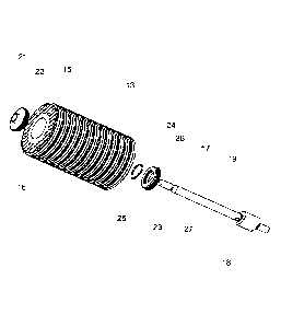
Fig. 2 shows an exploded view of an embodiment with one first 18 and one
second
physical structure 23. For similar parts, similar reference numbers have been
used as
in Fig. 1. In Fig. 2, the sealing means 24 comprises a sealing ring 24, e.g.
an 0-ring,
arranged at the inner surface 26 of the second physical structure 23. The 0-
ring 24 is
seen to have a non-circular shape which corresponds to the inner periphery of
the sec-
ond physical structure 23. Similarly, the outer periphery of the cross section
of the first
physical structure 18 corresponds to the inner periphery of the cross section
of the
second physical structure 23. The longitudinal axis of the first physical
structure 18 may
converge with the central axis A of the oil filtration unit 2. When the oil
filter 13 is insert-
ed into the oil filtration unit 2, the oil filter 13 comprising the second
physical structure
23 is then inserted on top of the stay bolt 19 so that the stay bolt 19
penetrates the cen-
tral opening 15 of the oil filter 13. When the second physical structure 23
touches the
first physical structure 18, the oil filter 13 can be rotated in relation to
the central axis A
of the oil filtration unit 2 until the periphery of the cross sections of the
first 18 and sec-
ond physical structures 23 are oriented and angled correctly according to each
other.
Thus, the first 18 and second physical structures 23 can engage each other by
press-
ing the oil filter 13 further onto the stay bolt 19. If the second physical
structure 23 is
not correctly oriented in relation to the first physical structure 18, the oil
filter 13 may
CA 02949299 2016-11-16
WO 2015/177274 PCT/EP2015/061243
17
not be installed correctly in the oil filtration unit 2. It is foreseen within
the present in-
vention that the cross-sectional shape of the first 18 and/or second physical
structure
23 may be un-uniform over the whole longitudinal extension of the first 18
and/or sec-
ond physical structure 23, i.e. that only part of the cross-sectional shapes
of the first
and/or second physical structures may correspond to each other.
Fig. 3 shows a cross section of a second physical structure 23. The inner
periphery is
seen to have a non-circular shape. The first physical structure 18 has a
mating outer
periphery, where the diameter/size of the second physical structure 23 is
equal to or
slightly larger than the outer diameter/size of the first physical structure
18. Other
shapes and sizes are foreseen within the scope of the present invention.
Fig. 4 shows an exploded view of an embodiment with two first 18,18' and
second
physical structures 23,23'. For similar parts, similar reference numbers have
been used
as in the previous figures. In the figure, a first 16 and a second planar
structure 17 are
attached in separate ends of the oil filter 13. One second physical structure
23' is ar-
ranged in the first planar structure 16, and one second physical structure 23
is ar-
ranged in the second planar structure 17. A sealing means 24 in the form of an
0-ring
24 is arranged at the inner surface 26,26' of each of the second physical
structures
23,23'. One first physical structure 18,18' is arranged in the vicinity of
each of the ends
of a central projection 19 in the form of a stay bolt 19, so that they can
each engage
their respective second physical structure 23,23' and thus form a respective
first 18,23
and second set 18,23' of first and second physical structures. Said two sets
18,23;18',23' are seen to be angled axially in relation to each other, but may
also not
be angled. In some cases, making use of one first 18 and second physical
structure 23
could possibly be insufficient to avoid installation of the wrong type of oil
filter 13. After
being operated for a long time, the first physical structure 18 could be at
risk of being
worn out of shape which could result in another type of oil filter 13 fitting
into place. Fur-
thermore, making use of one first 18 and second physical structure 23 could in
some
cases open up for a deliberate amendment of the first physical structure 18
and thus
the type of oil filter 13 used. Instead, making use of two first 18,18' and
two second
physical structures 23,23' minimises the above-mentioned risks of wrong use of
the oil
filtration unit 2 as not one physical structure 18, but two have to be worn
out of shape
or amended. A further advantage is that having two first 18,18' and second
physical
structures 23,23' increases the number of different types of oil filters 18
that can be de-
signed.
CA 02949299 2016-11-16
WO 2015/177274 PCT/EP2015/061243
18
Figs. 5a and 5b show an exploded view of an embodiment with several first 18
and
second physical structures 23, seen from opposite ends. For similar parts,
similar ref-
erence numbers have been used as in the previous figures. In Fig. 5a, the oil
filter 13
has been closed at the one end by a closed first end surface 28 of the oil
filter 13. At
the opposite end of the oil filter 13, a second end surface 29 of the oil
filter 13 compris-
es a second physical structure 23 arranged at the central axis B of the oil
filter 13 and
defining a through-going opening of the second end surface 29. Two further
second
physical structures 23%23" are arranged away from said central axis B, and are
not
through-going. The three second physical structures 23,23%23" have separate
second
cross-sectional shapes. Corresponding first physical structures 18,18,18" (not
shown)
are arranged at the end surface 5 of the oil filtration unit 2. The inner
surface 26 of the
second physical structure 23 arranged at the central axis B of the oil filter
13 consti-
tutes a sealing means. The filtered oil exits the filter via the opening 30.
In Fig. 5b, the embodiment is shown from the opposite end. The three first
physical
structures 18,18,18" are seen arranged at the inner end surface 5 of the oil
filtration
unit 2. The outer periphery of the cross section of the first physical
structures
18,18,18" mate with the inner periphery of the cross section of the respective
second
physical structures 23,23%23".
Figs. 6a and 6b show an exploded view of an embodiment with several first and
sec-
ond physical structures, both seen in a perspective view. For similar parts,
similar ref-
erence numbers have been used as in the previous Figs. In Fig. 6a, the oil
filter 13, an
end surface 31 of the oil filter 13 and an inner end surface 5 of the oil
filtration unit 2 is
seen.
Said end surface 31 of the oil filter 13 is shown as separated from the oil
filter 13 and
as shown may have the form of a disc. However, the end surface 31 may be assem-
bled with the oil filter 13, e.g. by use of an adhesive, before introduction
of the oil filter
13 into the inner opening 7 of the oil filtration unit 2 so as to facilitate
easy handling of
the oil filter 13 and to minimise the risk of oil leakage via the interface
between the oil
filter 13 and the end surface 31.
The end surface 31 of the oil filter 13 may have a size and shape so that the
end sur-
face 31 and the oil filter 13 together form a uniform oil filter 13 when
assembled. Thus,
CA 02949299 2016-11-16
WO 2015/177274 PCT/EP2015/061243
19
when the oil filter 13 has e.g. a substantially cylindrical shape, the end
surface 31 may
have the shape of a disc and have a width similar to the width of the
cylindrical oil filter
13 as is illustrated in Fig. 6a.
Thus, the end surface 31 may comprise a material similar to the material of
the oil filter
13, such as any natural or synthetic polymer, e.g. cellulose material.
The end surface 31 may comprise one or more second physical structures as
illustrat-
ed in Fig. 6a in which a first 23 (not shown), second 23' and third 23" second
physical
structure are arranged on the side oriented away from the oil filter 13 and
oriented to-
wards the inner end surface 5 of the oil filtration unit 2. The first 23,
second 23' and
third 23" second physical structures may be arranged along an outer edge 32 of
the
end surface 31 relative to a longitudinal axis of the end surface 31 and to
the central
axis B of the oil filter 13.
The inner end surface 5 of the oil filtration unit 2 is illustrated as a disc
in Fig. 6a. How-
ever, it is understood within the concept of the present invention that said
inner end
surface 5 may be a separate element which may be inserted into an existing oil
filtra-
tion unit 2 comprising side walls (such as a side surface 6) and an existing
inner end
surface 5 and be mounted on said existing inner end surface 5. Alternatively,
the inner
end surface 5 may be connected to side walls (such as a side surface 6) and
thus to-
gether form e.g. the first part 3 of the oil filtration unit 2, or the inner
end surface 5 may
be produced together with the side walls of the oil filtration unit 2 and form
a unit.
The inner end surface 5 may comprise an opening 33 through which filtered oil
may
flow from the central opening 15 of the oil filter 13 to the outlet tube 12 of
the oil filtra-
tion unit 2. The opening 33 may be arranged along the longitudinal axis of the
inner
end surface 5 and thus along the central axis A of the oil filtration unit 2
as illustrated in
Fig. 6a, but may also be arranged away from said longitudinal axis of the
inner end sur-
face 5 depending on location of the outlet tube 12.
The inner end surface 5 is illustrated as comprising three first physical
structures, i.e. a
first 18, second 18' and third 18" which are arranged on the inner end surface
5 and
may comprise a shape so that they may mate with the three second physical
structures
23,23%23" of the end surface 31 of the oil filter 13. Thus, said three first
physical struc-
tures 18,18',18" may be arranged near an outer edge 34 of the inner end
surface 5 of
CA 02949299 2016-11-16
WO 2015/177274 PCT/EP2015/061243
the oil filtration unit 2 and may as such be arranged in a circle. Thus, as
the first and
second physical structures may be arranged in a circle on the end surface 31
of the oil
filter 13 and on the inner end surface 5 of the oil filtration unit 2,
respectively, the pairs
of first and second physical structures, which are arranged to mate with each
other,
5 may be angled axially relative to each other.
The inner end surface 5 may comprise an elevation 35. In Fig. 6a, it is
illustrated that
the elevation 35 may form a closed path and may form a circle on the inner end
surface
5. As furthermore illustrated in Fig. 6a, the elevation 35 may run over each
of the first
10 physical structures 18,18,18". However, the elevation 35 may also have a
non¨
circular shape and/or may run past each of the first physical structures
18,18,18".
When the oil filter 13 is introduced in the inner opening 7 of the oil
filtration unit 2, the
oil filter 13 is moved in a direction along the central axis A of the oil
filtration unit 2 to-
15 wards the inner end surface 5 so that the respective first 18,18,18" and
second physi-
cal structures 23,23%23" mate with each other, and the elevation 35 comes into
contact
with the end surface 31 of the oil filter 13 and protrudes or cuts into the
oil filter 13.
Thus, sealing is provided between the oil filtration unit 2 and the oil filter
13. In this way,
the oil to be filtered is prevented from flowing from the inner opening 7 of
the oil filtra-
20 tion unit 2 to the central opening 15 of the oil filter 13 via the
interface between said in-
ner end surface Sand said end surface 31 and thus bypassing the oil filter 13.
In Fig. 6b, the oil filter 13, the end surface 31 of the oil filter 13 and the
inner end sur-
face 5 of the oil filtration unit 2 are seen from the opposite end. In Fig.
6b, the three
second physical structures 23,23%23" are seen to be arranged on the end
surface 31 of
the oil filter 13, and being angled axially relative to each other. The end
surface 31 of
the oil filter 13 may comprise an opening 36 to facilitate that filtered oil
may flow from
the central opening 15 of the oil filter 13 to the opening 33 of the inner end
surface 5.
Fig. 7 shows a cut-out of the exploded view of Fig. 6a and shows inter alia
the eleva-
tion 35 arranged on the inner end surface 5 of the oil filtration unit 2. The
elevation 35
may form a closed path around the opening 33 of the inner end surface 5 and/or
around the central opening 15 of the oil filter 13. When the oil filter 13 has
been insert-
ed in the oil filtration unit 2, the elevation 35 may thus protrude or cut
into the end sur-
face 31 of the oil filter 13, at least partly. The width of the elevation 35
may decrease
with distance from the inner end surface 5 of the oil filtration unit 2 and
may therefore
CA 02949299 2016-11-16
WO 2015/177274 PCT/EP2015/061243
21
have the shape of the edge of a knife so as to facilitate the ability of the
elevation to
protrude or cut into the oil filter 13.
Figs. 8a and 8b show an exploded view of an embodiment with several first and
sec-
ond physical structures, both shown in a perspective view. For similar parts,
similar ref-
erence numbers have been used as in the previous Figs. In Figs. 8a and 8b, the
end
surface 31 of the oil filter 13 has been assembled with the oil filter 13,
e.g. by use of a
liquid and/or hermetically tight attachment, e.g. by use of an adhesive.
Modifications and combinations of the above principles and designs are
foreseen within
the scope of the present invention.