Some of the information on this Web page has been provided by external sources. The Government of Canada is not responsible for the accuracy, reliability or currency of the information supplied by external sources. Users wishing to rely upon this information should consult directly with the source of the information. Content provided by external sources is not subject to official languages, privacy and accessibility requirements.
Any discrepancies in the text and image of the Claims and Abstract are due to differing posting times. Text of the Claims and Abstract are posted:
| (12) Patent: | (11) CA 2949392 |
|---|---|
| (54) English Title: | A MOULD TOOL FOR INJECTION MOULDING |
| (54) French Title: | OUTIL DE TYPE MOULE POUR LE MOULAGE PAR INJECTION |
| Status: | Granted and Issued |
| (51) International Patent Classification (IPC): |
|
|---|---|
| (72) Inventors : |
|
| (73) Owners : |
|
| (71) Applicants : |
|
| (74) Agent: | SMART & BIGGAR LP |
| (74) Associate agent: | |
| (45) Issued: | 2021-11-30 |
| (86) PCT Filing Date: | 2015-05-28 |
| (87) Open to Public Inspection: | 2015-12-03 |
| Examination requested: | 2020-01-13 |
| Availability of licence: | N/A |
| Dedicated to the Public: | N/A |
| (25) Language of filing: | English |
| Patent Cooperation Treaty (PCT): | Yes |
|---|---|
| (86) PCT Filing Number: | PCT/DK2015/050136 |
| (87) International Publication Number: | DK2015050136 |
| (85) National Entry: | 2016-11-17 |
| (30) Application Priority Data: | ||||||
|---|---|---|---|---|---|---|
|
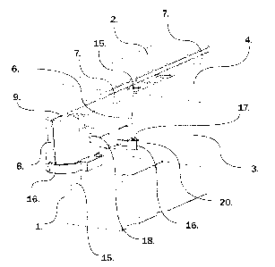
An injection-moulding mould configured for being mounted in an injection- moulding apparatus for automated moulding of work pieces in plastics, said injection-moulding mould comprising at least two separate mould parts that are separated by a mould separation face, and wherein at least one first mould part (1) is configured with an outer frame (2) in which is configured at least one space (14) which is open relative to the mould separation face, in which is mounted at least one exchangeable mould insert (3), and wherein the exchangeable mould insert (3) has a support plate (16) and the mould insert has a recess (20) into which the support plate (16) extends to the effect that the support plate (16) secures the mould insert (3) in the open space (14).
L'invention concerne un moule de moulage par injection conçu pour être monté dans un appareil de moulage par injection pour le moulage automatisé de pièces en matières plastiques, ledit moule de moulage par injection comprenant au moins deux parties de moule séparées qui sont séparées par une face de séparation de moule, au moins une première partie de moule (1) étant pourvue d'un cadre externe (2) dans lequel se trouve au moins un espace (14) qui est ouvert par rapport à la face de séparation de moule, dans lequel est monté au moins une empreinte rapportée interchangeable (3), l'empreinte rapportée interchangeable (3) ayant une plaque support (16) et l'empreinte rapportée ayant un creux (20) dans lequel la plaque support (16) s'étend pour amener la plaque support (16) à bien fixer l'empreinte rapportée (3) dans l'espace ouvert (14).
Note: Claims are shown in the official language in which they were submitted.
Note: Descriptions are shown in the official language in which they were submitted.
2024-08-01:As part of the Next Generation Patents (NGP) transition, the Canadian Patents Database (CPD) now contains a more detailed Event History, which replicates the Event Log of our new back-office solution.
Please note that "Inactive:" events refers to events no longer in use in our new back-office solution.
For a clearer understanding of the status of the application/patent presented on this page, the site Disclaimer , as well as the definitions for Patent , Event History , Maintenance Fee and Payment History should be consulted.
| Description | Date |
|---|---|
| Inactive: Grant downloaded | 2021-12-08 |
| Inactive: Grant downloaded | 2021-12-08 |
| Inactive: Grant downloaded | 2021-12-01 |
| Inactive: Grant downloaded | 2021-12-01 |
| Grant by Issuance | 2021-11-30 |
| Letter Sent | 2021-11-30 |
| Inactive: Cover page published | 2021-11-29 |
| Pre-grant | 2021-10-15 |
| Inactive: Final fee received | 2021-10-15 |
| Notice of Allowance is Issued | 2021-09-17 |
| Letter Sent | 2021-09-17 |
| Notice of Allowance is Issued | 2021-09-17 |
| Inactive: Approved for allowance (AFA) | 2021-08-03 |
| Inactive: Q2 passed | 2021-08-03 |
| Amendment Received - Response to Examiner's Requisition | 2021-06-23 |
| Amendment Received - Voluntary Amendment | 2021-06-23 |
| Inactive: Report - No QC | 2021-02-23 |
| Examiner's Report | 2021-02-23 |
| Common Representative Appointed | 2020-11-07 |
| Inactive: COVID 19 - Deadline extended | 2020-05-14 |
| Letter Sent | 2020-01-28 |
| Request for Examination Received | 2020-01-13 |
| Request for Examination Requirements Determined Compliant | 2020-01-13 |
| All Requirements for Examination Determined Compliant | 2020-01-13 |
| Common Representative Appointed | 2019-10-30 |
| Common Representative Appointed | 2019-10-30 |
| Inactive: Cover page published | 2016-12-21 |
| Inactive: Notice - National entry - No RFE | 2016-11-29 |
| Application Received - PCT | 2016-11-25 |
| Inactive: IPC assigned | 2016-11-25 |
| Inactive: IPC assigned | 2016-11-25 |
| Inactive: First IPC assigned | 2016-11-25 |
| Inactive: IPRP received | 2016-11-18 |
| National Entry Requirements Determined Compliant | 2016-11-17 |
| Application Published (Open to Public Inspection) | 2015-12-03 |
There is no abandonment history.
The last payment was received on 2021-05-17
Note : If the full payment has not been received on or before the date indicated, a further fee may be required which may be one of the following
Patent fees are adjusted on the 1st of January every year. The amounts above are the current amounts if received by December 31 of the current year.
Please refer to the CIPO
Patent Fees
web page to see all current fee amounts.
| Fee Type | Anniversary Year | Due Date | Paid Date |
|---|---|---|---|
| Basic national fee - standard | 2016-11-17 | ||
| MF (application, 2nd anniv.) - standard | 02 | 2017-05-29 | 2017-04-20 |
| MF (application, 3rd anniv.) - standard | 03 | 2018-05-28 | 2018-04-24 |
| MF (application, 4th anniv.) - standard | 04 | 2019-05-28 | 2019-04-25 |
| Request for examination - standard | 2020-05-28 | 2020-01-13 | |
| MF (application, 5th anniv.) - standard | 05 | 2020-05-28 | 2020-05-18 |
| MF (application, 6th anniv.) - standard | 06 | 2021-05-28 | 2021-05-17 |
| Final fee - standard | 2022-01-17 | 2021-10-15 | |
| MF (patent, 7th anniv.) - standard | 2022-05-30 | 2022-05-16 | |
| MF (patent, 8th anniv.) - standard | 2023-05-29 | 2023-05-15 | |
| MF (patent, 9th anniv.) - standard | 2024-05-28 | 2024-05-22 |
Note: Records showing the ownership history in alphabetical order.
| Current Owners on Record |
|---|
| LEGO A/S |
| Past Owners on Record |
|---|
| JENS STAMP LAMBÆK |

