Note: Descriptions are shown in the official language in which they were submitted.
1
METALLIC BIPOLAR PLATE WITH RESILIENT SEAL COMPRISING BEAD WITH
ELASTOMER-FILLED RECESS, AND ELECTROCHEMICAL SYSTEM COMPRISING
SAME
The present invention relates to a metallic bipolar plate with a resilient
sealing
arrangement as well as to an electrochemical system with a plurality of bipo-
lar plates of the kind mentioned.
Known electrochemical systems, such as for instance fuel cell systems or elec-
trochemical compressor systems like electrolyzers, usually comprise a stack of
electrochemical cells, which each are separated from each other by bipolar
plates. Such bipolar plates may for instance serve for the electrical
contacting
of the electrodes of the individual electrochemical cells, e.g. of fuel cells,
and/or for the electrical connection of adjoining cells, e.g. series
connection of
the cells. The bipolar plates may also comprise a channel structure or form a
channel structure, which is established for the supply of the cells with one
or
several media and/or for the removal of reaction products. The media may
for instance be fuels, e.g. hydrogen or methanol, reaction gases, e.g. air or
Date Recue/Date Received 2021-09-27
CA 02949586 2016-11-18
WO 2015/177365
PCT/EP2015/061466
2
oxygen or coolant. Such a channel structure is usually arranged in an electro-
chemically active area, thus in the gas distribution structure, also referred
to
as flow field. Further, the bipolar plates may be designed for the guidance of
heat produced during the transformation of electrical or chemical energy in
the electrochemical cell as well as for the sealing of different media or
coolant
channels against each other and/or to the outside. Typically, the bipolar
plates
of a stack comprise passage openings flush with each other. These then form
channels through which the media and/or reaction products can be guided to
or removed from the electrochemical cells between adjacent bipolar plates of
the stack. The electrochemical cells may for instance each comprise one or
several membrane-electrode assemblies, abbreviated as MEA, with polymer-
electrolyte membranes, abbreviated as PEM. The MEA may comprise one or
several gas diffusion layers, which usually are oriented towards the bipolar
plates and which are for instance realized as metallic or carbon fleece.
For the sealing of the passage openings mentioned in a bipolar plate in a
stack
and/or for the sealing of the channel structure in the electrochemically
active
area, the bipolar plates known comprise sealing arrangements with at least
one bead running parallel to the plane of the plate of the bipolar plate. For
the reduction of material and weight of the system, one uses beads with a
material strength or material thickness as small as possible. During the as-
sembly of the stack, the bead is compressed in a first step. In a second step,
a
compression and relaxation of the bead occurs during the operation of the
bipolar stack. Known beads of the kind mentioned are however very limited
with respect to their relaxation. This is why they often encounter an
irreversi-
ble plastic deformation during the compression of the bipolar plates in the
stack, in particular during the assembly of the stack. The bipolar plates in
gen-
eral have a higher lifetime expectation than do polymer-electrolyte mem-
branes or MEAs. For this reason, it can happen that used bipolar plates are
assembled with new MEAs. The bipolar plates of the state of the art can only
be reused in a further stack of bipolar plates with new MEAs to a very limited
extent as usually, their sealing function as a consequence of the plastic de-
formation does not conform to the requirements.
It is therefore the object of the present invention to provide for a bipolar
plate
with a seal based on a bead which shows a better resiliency behavior with a
3
material strength as small as possible and at the same time guarantees for a
sealing behavior as good as possible.
This object is solved by a metallic bipolar plate with a sealing arrangement
as
described herein.
To this end, a metallic bipolar plate for an electrochemical system is pro-
posed, which comprises a resilient sealing arrangement with at least one bead
extending parallel to a plane of the plate of the bipolar plate;
where the bead, orthogonal to the extension of the respective bead, shows an
M-shaped cross-section with lateral elevations and a groove formed between
the two lateral elevations;
where the lateral elevations have inner flanks pointing towards the groove
and the height of the flanks of the inner flanks which extends orthogonal to
the plane of the plate starting from the vertex of the groove, which is the
deepest point of the groove, to the crest point of the respective lateral
eleva-
tions, which is the highest point of the lateral elevations, and
where the groove is filled with an elastomer.
Compared to known bipolar plates of the kind mentioned above, the bipolar
plate mentioned here is characterized in that the elastomer extends over the
crest points of the lateral elevations over the entire extension of the bead
orthogonal to the plane of the plate and that the elastomer over the entire
course of the bead starting at the crest of the groove of the M-shaped cross
section of the bead at least over 50 percent of the flank height reaches to
the
inner flanks of the lateral elevations and covers them, so that during the com-
pression of the bipolar plate orthogonal to the plane of the plate, a pressure
force exerted on the elastomer is introduced into the bead via the elastomer.
Further, an electrochemical system is proposed, in particular a fuel cell
stack
or an electrolyzer, with a plurality of metallic bipolar plates of the kind de-
scribed and with a plurality of electrochemical cells each arranged between
the bipolar plates. In the electrochemical system, the bipolar plates and the
electrochemical cells are stacked along a stacking direction and exposable or
exposed to a mechanical pressure along the stack direction.
Date Recue/Date Received 2021-09-27
CA 02949586 2016-11-18
WO 2015/177365
PCT/EP2015/061466
4
Thus, the elastomer in each case along a section of the inner flanks, which
corresponds to at least 50 percent of the height of the flank of the
respective
inner flank, is in direct contact with the inner flanks, namely along the
cross
section orthogonal to the respective course of the bead and on both sides of
the crest of the groove located at the bottom of the groove. The inner flanks
preferably extend from the crest of the groove to the crest point of the re-
spective lateral elevations. The two inner flanks this way preferably comprise
the bottom and the side sections of the groove.
The extension of the sealing arrangement and the course of the bead, respec-
tively, can be given by a central line of the bead, which as does the bead, ex-
tends parallel to the plane of the plate. If it is spoken about the cross-
section
of the bead at a particular position along the course of the bead is oriented
orthogonal to the course of the bead, this preferably means that the cross-
sectional plane intersects with a tangent drawn at the respective position on
the center line of the bead. Thus, the cross-sectional plane therefore is pref-
erably oriented orthogonal to the plane of plate. If nothing else is
mentioned,
the terms õcross-section of the sealing arrangement", õcross-section of the
bead" or õcross-section" therefore in this document shall in each case mean a
cross-section along a plane, which is oriented orthogonal to the respective
course of the plane and orthogonal to the plane of plate.
The cross-sectional geometry of the bead may remain the same over its entire
course, it may however also change. It is for instance possible to realize the
flanks of the beads in areas remote from the bolt positions steeper than in
areas close to the bolt positions, in order to achieve a regular introduction
of
forces. They may also be realized smaller and/or higher in areas remote from
screw holes than in areas close to screw holes. In the same way, beads can be
realized lower or wider or with flatter flanks in curved areas than in areas
that
extend straight. If the embossed geometry of the bead changes along its
course, then the cross section of the elastomer may change with the one of
the bead to the same or to a different degree or remain the same.
In an area, where the beads from a macroscopic point of view have an un-
changed extension direction, they may extend straight in a microscopic sense,
CA 02949586 2016-11-18
WO 2015/177365
PCT/EP2015/061466
too, but they may also alternate around the extension direction and extend
wave-shaped in a top view. The last variant with comparable cross-sectional
geometries results in higher stiffness.
5 In the following, the plane of plate of the bipolar plate is also
referred to as x-
y plane. The stack direction along which the bipolar plates in an electrochemi-
cal system with a plurality of bipolar plates of the kind mentioned can be
stacked or are stacked, in the following is therefore also referred to as the
z-
direction. The x-, y- and z-direction this way form the axis of a right-handed
Cartesian coordinate system. The height of the bead thus typically extends
along the z-direction.
With the M-shaped geometry of the cross-section of the bead, at least one of
the two properties stiffness and resiliency behavior of the bead is improved
without the respective other being significantly deteriorated, in particular
along the z-direction. As the elastomer over the entire course of the bead pro-
jects over the entire course of the bead orthogonal to the plane of plate over
the crests of the lateral elevations and as the elastomer over the entire
course
of the bead, starting at the vertex of the recess of the M-shaped cross-
section
of the bead at least over 50 percent of the height of the flanks reaches to
the
inner flanks of the lateral elevations and covers them, the elastomer is suffi-
ciently stably arranged or anchored in the recess in the top of the bead, so
that it cannot deviate laterally, thus meaning orthogonal to the respective
course of the bead and parallel to the x-y-plane to the outward, thus it
cannot
flow away. Creeping of the elastomer during compression of the bipolar plate
can be avoided this way.
During the compression of the bipolar plate along the z-direction, the bead
can elastically, meaning reversibly, deform; doing so, e.g. the width of the
recess in the top of bead orthogonal to the course of the bead reduces. The
elastomer may thus be compressed during the deformation of the bead, e.g.
in a direction orthogonal to the respective course of the bead. This way, a
plastic, meaning irreversible, deformation of the bead can be avoided to the
largest degree. When the bead is again unloaded, e.g. during the removal of
the bipolar from the stack, then the elastomer typically takes on its
previous,
non-compressed shape and this way causes an advantageous spring-back of
CA 02949586 2016-11-18
WO 2015/177365
PCT/EP2015/061466
6
the bead. This way, it is also possible to regulate the characteristic curve
of
the bead, thus the elastic deformation ¨ measured in mm ¨ dependent on the
compression force ¨ measured in Nimm ¨ per unit of length along the course
of the bead exerted on the bead by means of the hardness or the elasticity of
the elastomer used. As a consequence of the increased spring-back behavior,
the sealing effect of the sealing arrangement of the bipolar plate compressed
in the stack is improved, too.
A particular anchoring of the elastomer in the recess in the top of bead, a
par-
ticular introduction of the force into the bead used for the compression of
the
bipolar plate orthogonal to the plane of plate as well as an increase of the
stiffness of the sealing arrangement can be achieved in that the elastomer
reaches to the inner flanks of the lateral elevations and covers them over at
least 80 percent of the height of flanks along the entire course of the bead
starting at the vertex of the recess of the M-shaped cross-section of the
bead.
The stiffness and the spring-back behavior of the sealing arrangement can be
particularly set and controlled if the elastomer fills the recess of the M-
shaped
cross-section of the bead over the entire height of flanks, in fact preferably
everywhere along the course of the bead. This includes that an area which is
determined along the cross-section and therefore orthogonal to the respec-
tive course of the bead, which is enclosed by the inner flanks of the lateral
elevations and by a straight line connecting both crests of the lateral eleva-
tions, is in each case completely filled by the elastomer. In other words, the
recess shows no voids below the above mentioned straight line, thus between
the above mentioned straight line and the plane of plates.
A particularly regular introduction of the compression force exerted on the
bead during the compression of the bipolar plate along the z-direction can be
achieved in that the elastomer along the M-shaped cross-section of the bead
in one section, which extends from the crest of the first lateral elevation to
the crest of the second lateral elevation projects over the crests of the
lateral
elevations in a meniscus-like manner orthogonal to the plane of plates, name-
ly preferably over the entire course of the bead. With respect to the straight
line defined beforehand, which is determined by the two crests of the lateral
elevations of the bead, this means that the elastomer along the z-direction
CA 02949586 2016-11-18
WO 2015/177365
PCT/EP2015/061466
7
continuously projects over this straight line. Doing so, an outer side or
outer
surface of the elastomer pointing away from the bead, which side or surface,
respectively, extends from the crest of the first lateral elevation to the
crest of
the second lateral elevation, may extend continuously curved and cambered
outwardly, thus in a direction pointing away from the vertex of the recess.
If the elastomer does not completely cover the inner flanks, it nevertheless
rises starting at the interface to one of these inner flanks in the direction
of a
perpendicular through the vertex of the recess and on the other side of the
perpendicular through the vertex of the recess descends again. The rise and
descent here are preferably continuous, but in the area of the perpendicular
through the vertex of the recess, a plateau without change of height may
form, too.
If the bead extends straight, the sealing arrangement in its cross-section is
typically mirror-symmetric or essentially mirror-symmetric relative to a sym-
metry axis of the sealing arrangement. The symmetry axis then usually ex-
tends inside of the respective cross-sectional plane and orthogonal to the
plane of plate and intersects with the vertex of the recess. If the bead does
not extend straight, e.g. in corners or if it generally extends wave-shaped,
then deviations from this strict symmetry can be given.
A height of the elastomer determined along the z-direction can be maximal in
a central or middle section of the bead along the cross-section of the bead
and descend towards the lateral elevations of the bead monotonously. The
elastomer then in the central section mentioned in z-direction projects far-
thest over the lateral elevations of the bead. This can go along with the elas-
tomer having its maximum thickness also in the area where the projection of
the elastomer relative to the elevations of the metallic bead is maximal.
In order to increase the spring-back properties of the sealing arrangement,
the elastomer may be compressible. The elastomer may be a thermoplastic
elastomer, a fluoro polymer, such as a fluoro-polymer rubber, a perfluorated
rubber, a perfluoro-alkoxy polymer, a butadiene rubber, an acrylonitrile-
butadiene rubber, styrene-butadiene rubber, hydrated acrylonitrile-butadiene
rubber, ethylene-propylene-diene rubber, ethylene-propylene rubber, silicone
CA 02949586 2016-11-18
WO 2015/177365
PCT/EP2015/061466
8
rubber, fluoro-silicon rubber, polyacrylate rubber, ethylene-acrylate rubber
or
polyurethane or comprise one or several of the materials mentioned. The
elastomer may be applied into the recess of the bead using screen printing.
The sealing arrangement described even with a small material thickness of the
bead provides for a sufficient spring-back behavior. A material thickness of
the bead may therefore be smaller than 0.15 mm, preferably smaller than 0.1
mm, in particular advantageously smaller than 0.08 mm. For the same
amount of plates or fuel cells, respectively, within a fuel cell stack, one
there-
fore needs a smaller constructional height. This way, material cost and weight
can be saved. As an alternative, one can construct a stack with an increased
number of individual cells with unchanged constructional height.
Typically, a depth of the recess of the bead is smaller than a height of the
lat-
eral elevations of the bead. The recess along the z-direction thus normally
does not reach until the plane of plate. The vertex of the recess in this case
is
therefore distanced to the plane of plate. This can also contribute to an in-
crease of the spring-back properties of the sealing arrangement, as the bead
during compression of the bipolar plate in the area of the recess along the z-
direction towards the plane of plate may retreat without butting in the area
of
the recess. The plane of plate may for instance be defined by straight
sections
of the bipolar plate, which join to the outer flanks of the lateral elevations
of
the bead pointing away from the recess of the bead. Usually, the distance
between the vertex of the recess and the plane of plate amounts to at the
most 50 percent, preferably at the most 40 percent of the height of bead,
which is given by the distance of the crests of the lateral elevations of the
bead from the plane of plate along the z-direction.
For a sufficient anchoring of the elastomer in the recess of the bead, it can
be
advantageous if the height of flank of the inner flanks of the lateral
elevations
of the bead corresponds to at least 15 percent, preferably at least 20
percent,
particularly preferably at least 30 percent of the height of bead. The height
of
bead typically amounts to less than 0.7 mm, preferably less than 0.55 mm.
In order to increase the spring-back behavior of the sealing arrangement, the
outer flanks of the lateral elevations of the bead pointing away from the re-
CA 02949586 2016-11-18
WO 2015/177365
PCT/EP2015/061466
9
cess, can be realized with a small inclination, only. The outer flanks can
span
an angle of e.g. at least 300, preferably at least 45 , particularly
preferably at
least 50 with the z-direction of the along the cross-section of the bead.
The lateral elevations of the bead in their cross-section preferably show a
camber pointing away from the plane of plate, which camber in each case
connects the inner flank of the lateral elevation with the outer flank of the
lateral elevation. The spring-back behavior of the sealing arrangement can
also be improved in that a radius of curvature of this camber amounts to at
least 6 percent, preferably at least 9 percent of a width of the bead between
its feet. The width of the bead between its feet amounts e.g. to less than 3
mm, preferably less than 2.5 mm.
Further, in order to improve the spring-back behavior of the sealing arrange-
ment, the bead can be curved along the cross-section of the bead in the area
of the recess, at least in sections, at least in a central or middle section
along
the cross-section of the bead. A radius of curvature of this curvature in the
area of the recess can for instance amount to less than 50 percent, preferably
less than 40 percent of the width of the bead between its feet. In order to
increase the stiffness of the sealing arrangement, the cross-section of the
bead in the area of the recess may also be shaped wave-like.
For the passage of a liquid and/or gaseous medium, the bipolar plate can
comprise one or several passage openings orthogonal to the plane of plate. In
an electrochemical system with a plurality of bipolar plates of the kind pro-
posed here, the passage openings of adjacent bipolar plates are arranged, e.g.
at least partially flush in order to form one or several channels for the
supply
and/or removal of a liquid and/or gaseous medium. These channels then typi-
cally extend in stack direction through the stack of plates or through the en-
tire electrochemical system, respectively. The sealing arrangements of the
bipolar plates may then be arranged in such a way that they radially enclose
the opening of the bipolar plate mentioned and seal it towards the environ-
ment and/or towards the inward of the electrochemical system. The sealing
arrangements of the bipolar plates at least partially may be designed for the
sealing of the electrochemically active area of the electrochemical cells of
the
system.
CA 02949586 2016-11-18
WO 2015/177365
PCT/EP2015/061466
For a directed passage of a liquid and/or gaseous medium through the bead,
in particular orthogonal to the course of the bead, the outer flanks of the
bead may comprise one or several perforations or perforation holes. The liq-
5 uid and/or gaseous medium can be guided to e.g. an electrochemically
active
area of an electrochemical cell adjacent to the bipolar plate or fed away from
this cell through these perforations.
The bipolar plate may comprise two partial plates arranged in parallel to each
10 other and mechanically connected to each other. They may for instance
serve
for the contacting of electrodes of two adjacent electrochemical cells of the
electrochemical system, which are each arranged on different sides of the
bipolar plate. The bead of the sealing arrangement may then be realized one-
piece with a partial plate. The bead in this case is thus formed by the respec-
tive partial plate itself.
In a particular embodiment, the first partial plate may comprise a first
sealing
arrangement of the kind mentioned, with the first bead and the first partial
plate being realized as one-piece. Accordingly, the second partial plate in
this
embodiment comprises a second sealing arrangement of the kind mentioned
with a second bead, where the second bead and the second partial plate are
realized as one-piece, too. The first bead of the first partial bead and the
se-
cond bead of the second partial plate then can enclose a cavity for the guid-
ance of a liquid and/or gaseous medium between the first bead and the se-
cond bead.
The two partial plates of a bipolar plate at least at the outside of the bead
are
adhesively connected to each other. Preferably, a continuous welding seam,
in particular a laser welded seam is used for the connection of both partial
plates. In particular if the bead is also used for the guidance of a liquid
and/or
gaseous medium, it is preferred if a continuous welding seam is arranged on
both sides of the bead. As an alternative, stitched or dotted welding seams
can be used, too. Thus, the welding seams are preferably provided in the area
of the feet of the beads or distanced to the bead, thus adjacent to the feet
of
the beads.
CA 02949586 2016-11-18
WO 2015/177365
PCT/EP2015/061466
11
Embodiments of the invention are illustrated in the drawings and will be fur-
ther explained using the following description. It is shown in:
Figure 1 Schematically a perspective view of an electrochemical
system
with a plurality of bipolar plates and electrochemical cells ar-
ranged between the bipolar plates;
Figure 2 Schematically one of the bipolar plates of the
electrochemical
system from figure 1 in a top view;
Figure 3 Schematically two neighboring bipolar plates of an
electro-
chemical system comparable to figure 1 with an electrochemi-
cal cell arranged between the bipolar plates;
Figure 4 Schematically a cross-section of a first embodiment of a sealing
arrangement according to the invention;
Figure 5a Schematically the sealing arrangement from figure 4 in a
non-
loaded state;
Figure 5b Schematically the sealing arrangement from figure 4 in a
loaded
state;
Figure 6 Schematically a cross-section of a second embodiment of
the
sealing arrangement according to the invention;
Figure 7 Schematically a cross-section of a third embodiment of
the
sealing arrangement according to the invention;
Figure 8 Schematically a cross-section of a fourth embodiment of the
sealing arrangement according to the invention;
Figure 9 Schematically a bipolar plate according to the invention
with a
sealing arrangement for sealing of a passage opening in the bi-
polar plate;
CA 02949586 2016-11-18
WO 2015/177365
PCT/EP2015/061466
12
Figure 10 Schematically a bipolar plate according to the invention
with a
sealing arrangement for sealing of a passage opening in the bi-
polar plate, where the outer flanks of a bead of the sealing ar-
rangement comprise perforations for the guidance of a liquid
and/or gaseous medium;
Figure 11 Schematically a bipolar plate according to the invention
with a
first and a second partial plate, wherein a first bead of the first
partial plate and a second bead of the second partial bead en-
close a cavity for the guidance of a gaseous and/or liquid medi-
um;
Figure 12 The comparison of the load-deflection curves of beads of
bipo-
lar plates according to the invention as well as of bipolar plates
according to the state of the art; and
Figure 13 Explanatory cross-sections relating to figure 12.
Figure 1 shows an electrochemical system 1, which comprises hydrogen fuel
cells connected electrically in series. In alternative embodiments, the system
1, can also be an electrochemical compressor or an electrolyzer. These are not
different from each other with respect to their constructive design, but essen-
tially with respect to the fluids guided towards and away from the MEA as
well as with respect to the generation or the supply of electrical energy.
The electrochemical system 1 comprises a stack 2 with a plurality of metallic
bipolar plates and with electrochemical cells for the transformation of chemi-
cal energy into electrical energy each arranged between adjacent bipolar
plates. The electrical cells are connected in series connection. The bipolar
plates and the cells of the stack are stacked along the z-direction 5 and ar-
ranged between endplates 3 and 4. The planes of the plates of the bipolar
plates of the stack 2 are each arranged in parallel to a x-y plane. Together
with
the z-direction 5, the x-direction 6 and the y-direction 7 span a right-handed
Cartesian coordinate system. Along the z-direction 5, the bipolar plates and
the cells of the stack 2 are charged with a mechanical pressure via the end
plates 3 and 4 and kept together, e.g. using screws or bolts not shown here.
CA 02949586 2016-11-18
WO 2015/177365
PCT/EP2015/061466
13
The endplate 4 comprises a number of ports 8, via which liquid and/or gase-
ous media can be supplied to and/or liquid and/or gaseous media can be re-
moved from the electrochemical system 1. It is for instance possible to supply
the system 1 via the ports 8 with a fuel, e.g. hydrogen, and a reaction gas,
e.g.
oxygen. It is further possible to remove the reaction products such as water
and air with a reduced oxygen content, and the heated coolant from the sys-
tem 1.
Figure 2 in a top-view shows a metallic bipolar plate 9 of the stack 2 in
figure
1, which is oriented parallel to the x-y plane. The bipolar plate 9 comprises
two mechanically connected partial plates 9a and 9b, wherein in figure 2, only
the first partial plate 9a is shown, the second partial plate 9b is covered.
The
bipolar plate 9 comprises passage openings 10a-h. The remaining bipolar
plates in the stack 2 of the electrochemical system 1 in figure 1 comprise pas-
sage openings corresponding to the passage openings 10a-h of the bipolar
plate 9. These passage openings of the bipolar plates in the stack 2 of the
sys-
tem 1 in figure 1 are oriented flush along the z-direction, so that they form
ducts for the guidance of the aforementioned liquid and/or gaseous media.
Thus, these ducts extend orthogonal to the planes of plate of the bipolar
plates through the stack 2 of the system 1. The ducts are in fluidic communi-
cation with the ports 8 at the endplate 4 of the system 1.
The partial plate 9a of the bipolar plate 9 further comprises a resilient
sealing
arrangement 11, which extends parallel to the plane of plate of the bipolar
plate 9, thus in the illustration in figure 2 parallel to the x-y plane. Here
and in
the following, recurring characteristics are referred to with the same refer-
ence numbers. The sealing arrangement is formed for the sealing of an area
28 against the environment of the system 1. The sealing arrangement 11
forms a closed curve and encircles the area 28 completely. The sealing ar-
rangements here extend with an oval basic shape along the oval passage
openings. In this respect, their extended areas do not extend straight, but
undulating, in order to provide the bead over its entire course with an essen-
tially unchanged stiffness. In a central rectangular partial area 29 of the
area
28, the partial plate 9a comprises a plurality of protrusions, which protrude
orthogonally from the plane of the plate. The partial area 29 between the
CA 02949586 2016-11-18
WO 2015/177365
PCT/EP2015/061466
14
adjacent bipolar plates 9 and 13 of the stack 2 is formed in order to take up
an
electrochemical cell 14, see figure 3. Here, the electrochemical cell 14 is a
bi-
polar plate for the transformation of chemical energy into electrical energy.
The channels formed between the protrusions of the partial area 29 serve for
the deliberate supply of fuel or of reaction gas to the electrochemically
active
area of the electrochemical cell 14 arranged in the partial area 29 between
the bipolar plates 9 and 13, see figure 3.
Apart from the sealing arrangement 11, the partial plate 9a of the bipolar
plate 9 comprises a number of further resilient sealing arrangements 12a-h,
which each are formed for the sealing of the channels formed by the passage
openings 10a-h against the area 28 or against the environment of the system
1. The sealing arrangements 12a-h each extend parallel to the plane of plate
of the bipolar plate 9, too, each form self-contained courses and encircle the
passage openings 10a-h in the bipolar plate 9 radially completely. The sealing
arrangements 11 and 12a-h each protrude orthogonally to the plane of plate
of the partial plate 9a from the partial plate 9a. The characteristics of the
resil-
ient sealing arrangements 11 as well as 12a-h will be further explained
further
below.
Figure 3 shows a cross-section in the y-z plane through a stack 1 similar to
figure 1. Figure 3 shows a bipolar plate 9 comparable to the bipolar plate 9
in
figure 2 with the metallic partial plates 9a and 9b and the second bipolar
plate
13 adjacent to the first bipolar plate 9 in the stack 2. The bipolar plates 9
and
13 have identical construction. The bipolar plate 13 comprises two mechani-
cally-connected metallic partial plates 13a and 13b, too. The partial plates
9a,
9b, 13a, 13b are each produced from stainless steel and have a material
thickness 23 of 0.075 mm orthogonal to the planes of the plates. In the
partial
area 29, the electrochemical cell 14 mentioned before is arranged between
the adjacent bipolar plates 9 and 13. The electrochemical cell 14 comprises an
electrolyte membrane 15, an anode 16, a cathode 17 as well as gas diffusion
layers 18 and 19. The electrically conductive gas diffusion layers 18 and 19
are
each arranged between the electrodes 16, 17 on the one hand and the bipolar
plates 9, 13 on the other hand.
Figure 3 shows the sealing arrangement 11 of the partial plate 9a in cross-
section. The sealing arrangement 11 comprises a metallic bead 20 and an elas-
CA 02949586 2016-11-18
WO 2015/177365
PCT/EP2015/061466
tamer 21. The bead 20 and the partial plate 9a of the bipolar plate 9 are
formed as one-piece. The bead 20 extends parallel to the plane of plate of the
bipolar plate 9 and protrudes orthogonally from the plane of plate of the bi-
polar plate 9. In the representation of figure 3, the bead 20 extends orthogo-
5 nal to the drawing plane along the x-direction 6 and orthogonally to its
exten-
sion direction, thus along the drawing plane of figure 3, the y-z plane, com-
prises an M-shaped cross-section with lateral elevations and a recess formed
between the lateral elevations, which is filled with the elastomer 21, see fig-
ure 4.
The second partial plate 9b of the bipolar plate 9 comprises a sealing ar-
rangement 22 structurally identical to the sealing arrangement 11 of the first
partial plate 9a with a metallic bead 24 and an elastomer 25, with the sealing
arrangement 22 extending parallel to the plane of plate of the bipolar plate
9,
as does the sealing arrangement 11. The bead 24 and the second partial plate
9b are formed as one-piece. The sealing arrangements 11 and 22 protrude
from the respective bipolar plate 9 in opposite directions orthogonal to the
plane of plate of the bipolar plate 9. In this respect, the sealing
arrangements
11 and 22 are designed in such a way that the cavity 26 formed between them
is also suited for the guidance or passage of one of the gaseous and/or liquid
media mentioned.
Laterally, thus in figure 3 along the y-direction, the cavity 26 formed by the
beads 20 and 24 between the partial plates 9a and 9b is sealed by welding
lines 27a and 27b extending continuously along the beads 20 and 24.
The bipolar plate 13 comprises a sealing arrangement 52 of identical construc-
tion than the sealing arrangement 11 of the bipolar plate 9. In order to seal
the area 28 situated between the bipolar plates 9 and 23, the sealing ar-
rangements 11 and 52 cooperate by enclosing the electrolyte membrane 15
of the cell 14 between them and by each being pressed in opposite directions
against the membrane 15.
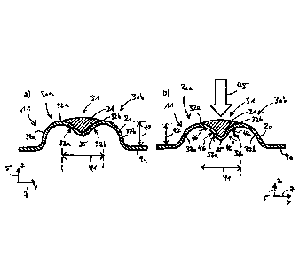
Figure 4 in a schematic representation shows a detailed view of a cross-
section of the sealing arrangement 11 of the partial plate 9a. It is a cross-
section along a plane which is oriented orthogonal to the plane of plate of
the
CA 02949586 2016-11-18
WO 2015/177365
PCT/EP2015/061466
16
bipolar plate 9 or its partial plate 9a and orthogonal to the course of the
seal-
ing arrangement 11, namely in an area without a perforation of the flank of
the bead.
The cross-section of the sealing arrangement given in figure 4 shows the me-
tallic bead 20 with lateral elevations 30a and 30b and a recess 31 formed be-
tween the lateral elevations 30a and 30b, which recess is filled with the elas-
tomer 21. The lateral elevations 30a and 30b each have their maximum height
t2 determined along the z-direction 5 and orthogonal to the plane of plate of
the partial plate 9a in crests 32a and 32b of the lateral elevations 30a and
30b. The plane of plate of the partial plate 9a is defined by straight
sections
33a and 33b of the partial plate 9b, which extend in y-direction 7 and which
adjoin to the bead 20 at feet points 34a and 34b of the bead 20 on both sides
of the bead 20. At the vertex 35 of the recess, the bead in the area of the re-
cess 31 has its smallest height t1, which is also determined orthogonal to the
plane of plate. The sealing arrangement 11 in its cross-section is symmetric
relative to an axis of symmetry, which extends orthogonal to the plane of
plate and intersects with the bead 20 at the vertex 35 of the recess 31.
A width b of a bead between its feet of the bead 20 extends in parallel to the
plane of plate from a foot point 34a to a foot point 34b over a length of 2.2
mm. The height t2 of the bead 20 in the embodiment shown here amounts to
0.5 mm. The height of the vertex 35 of the recess 31 amounts to about 0.25
mm, thus to 50 percent of the bead height t2. In varied embodiments, the
height t1 can also amount to less than 50 percent or less than 40 percent of
the bead height t2. The vertex thus does not reach into the plane of plate and
is distanced to the plane of plate. Usually, the height t1 of the bead 20 in
the
vertex 35 of the recess 31 amounts to at least 20 percent or at least 30 per-
cent of the bead height t2.
The lateral elevations 30a and 30b of the bead 20 comprise outer flanks 37a
and 37b pointing away from the recess 31, which extends from the foot point
34a till the crest 32a and from the foot point 34b till the crest 32b. In
order to
increase the spring-back behavior of the sealing arrangement 11, in particular
orthogonal to the plane of plate, the outer flanks 37a and 37b of the bead 20
are designed flat. Here, at least in sections, they span an angle of more than
CA 02949586 2016-11-18
WO 2015/177365
PCT/EP2015/061466
17
300 with the z-direction extending orthogonal to the plane of plate. Over at
least 30 percent of the height of bead t2, the outer flanks span an angle of
more than 30 with the z-direction.
The bead 20 further comprises inner flanks 38a and 38b facing the recess 31.
The inner flank 38a of the lateral elevation extends from the crest 32a of the
lateral elevation 30a to the vertex 35 of the recess 31, and the inner flank
38b
of the lateral elevation 30b until the vertex 35 of the recess 31. The inner
flanks 38a and 38b thus form the bottom or base and the sides of the recess
31. A height t1 of the inner flanks 38a and 38b extends orthogonally to the
plane of plate from the plane of the vertex 35 of the recess 31 till the plane
of
the crests 32a and 32b of the lateral elevations 30a and 30b. The height t1 of
the inner flanks 38a and 38b at the same time is a depth of the recess 31.
Here, the height t1 of the inner flanks 38a and 38b amounts to 50 percent of
the bead height t2. In modified embodiments, the height t1 of the inner flanks
38 and 38h preferably amounts to at least 15 percent, at least 20 percent or
at least 30 percent of the bead height t2. This serves for a particular
anchoring
of the elastomer 21 in the recess 31 of the bead 20, so that a deviation of
the
elastomer 21, in particular parallel to the plane of plate and orthogonal to
the
respective course of the bead 20 or of the sealing arrangement 11, is avoided
as effective as possible if during compression of the bipolar plates of the
stack
2¨ see figure 1- a compression force acts on the sealing arrangement 11 or-
thogonal to the plane of plate of the bipolar plate or along the z-direction
5,
respectively.
In the example described here, a distance measured parallel to the plane of
plate between the crest 32a of the lateral elevation 30a and the crest 32b of
the lateral elevation 30b amounts to 1 mm. The distance of the crests 32a and
32b parallel to the plane of plate thus amounts to approximately 45 percent
of the width b of the bead 20 between its feet. Preferably, the distance of
the
crests 32a and 32b from each other parallel to the plane of plate in modified
embodiments amounts to less than 50 percent of the width b of the bead 20
between its feet.
In the area of the crests 32a and 32b, the lateral elevations 30a and 30b of
the
bead each comprise a camber pointing away from the plane of plate. The
CA 02949586 2016-11-18
WO 2015/177365
PCT/EP2015/061466
18
camber of the bead 20 in the area of the crest 32a connects the outer flank
37a with the inner flank 38a of the lateral elevation 30a, and the camber of
the bead 20 in the area of the crest 32b connects the outer flank 37b with the
inner flank 38b of the lateral elevation 30b. In the area of the vertex 35 of
the
recess, the bead comprises a camber pointing towards the plane of plate. This
also has a positive effect on the spring-back behavior of the sealing arrange-
ment 11. Thus, the recess 31 is curved inside of the central section of the
cross-section of the bead. This central, curved section of the bead 20 here
extends over a length of about 0.25 mm. The length of the curved section of
the bead 20 in the area of the vertex 35 of the recess 31 thus amounts to at
least 10 percent of the width b of the bead 20 between its feet. In the exam-
ple illustrated here, the central curved section along the cross-section of
the
bead is symmetric relative to the vertex 35 of the recess 31. A radius of
curva-
ture not explicitly highlighted here of the bead 20 in the area of the vertex
35
of the recess 31 here amounts to 0.2 mm. in modified embodiments, the radi-
us of curvature of the bead 20 in the area of the vertex 35 of the recess 31
is
preferably less than 50 percent, less than 40 percent or less than 30 percent
of the width b of the bead 20 between its feet.
The elastomer 21 is a compressible elastomer, e.g. a silicon-based elastomer.
The elastomer 21 is printed onto the surface of the recess 31 in the bead top,
here in particular using screen printing. The elastomer 21 fills up the recess
31
of the bead 20 along the entire course of the sealing arrangement shown in
figure 2. The elastomer 21 along the cross-section of the bead in particular
completely fills up a surface 39, which is delimited by the inner flanks 38a
and
38b of the lateral elevations 30a and 30b and by a straight line 44, which con-
nects the crests 32a and 32b. The elastomer 21 thus starting at the vertex 35
of the recess 31 reaches over the entire height t1 of the inner flanks 38a and
38b of the lateral elevations 30a and 30b to the inner flanks 38a and 38b. In
other words, the elastomer 21 is immediate contact with the inner flanks 30a
and 30b starting at the vertex 35 of the recess 31 and up to the crests 32a
and
32b of the lateral elevations 30a and 30b and covers the inner flanks 30a and
30b completely. This serves for an anchoring of the elastomer in the recess 31
and provides for an as regular introduction of the compression force into the
bead 20 exerted on the sealing system 11 during the compression of the stack
2 orthogonal to the plane of plate and this way prevents a lateral deviation
CA 02949586 2016-11-18
WO 2015/177365
PCT/EP2015/061466
19
and creeping of the elastomer 21 during the compression of the stack 2. In the
example of figure 2, this is true along the entire closed curve of the sealing
arrangement 11, even in the areas, where the outer flanks 37a, 37b of the
bead show perforations 50.
In modified embodiments, the elastomer 21 starting at the vertex 35 of the
recess projects over at least 50 percent or at least over 80 percent of the
height t1 of the inner flanks 38a and 38b immediately to the inner flanks 38a
and 38b and covers the inner flanks 38a and 38b within this section in each
case completely. This, too, is true along the entire closed course of the
sealing
arrangement shown in figure 2. Figure 8 shows such a modified embodiment
of the sealing arrangement 11, where the elastomer over 85 percent of the
height t1 immediately reaches till the inner flanks 38a and 38b and covers the
inner flanks 38a and 38b in this section in each case completely. In the
upmost
15 percent of the height t1, the inner flanks are exposed.
Further, the elastomer 21 projects orthogonally to the plane of plate of the
bipolar plate 9 or of the partial plate 9a over the crests 32a and 32b of the
lateral elevations 30a and 30b, in fact along the entire closed curve of the
sealing arrangement 11 shown in figure 2. In particular, the elastomer 21 pro-
jects orthogonal to the plane of plate of the bipolar plate 9 or of the
partial
plate 9a, respectively, over the crests 32a and 32b along the entire section
which extends along the cross section from crest 32a of the lateral elevation
30a to the crest 32b of the lateral elevation 30b. At a crest 42 of the elasto-
mer 21, which is the highest point of the elastomer 21 relative to the plane
of
plate of the partial plate 9a, the elastomer projects orthogonal to the plane
of
plate plane of plate by a height h over the crests 32a and 32b. The height h
here amounts to 0.05 mm. The elastomer here thus projects by at least 10
percent of the height of bead t2 over the bead 20. The crest 42 of the elasto-
mer 21 is situated on the axis of symmetry 36. The elastomer thus has its max-
imum height in a central section along the cross-section of the bead.
Along the axis of symmetry 36 of the sealing arrangement 11 or of the bead
20, the elastomer 21 has its largest thickness 43 determined orthogonal to the
plane of plate, which here amounts to about 50 percent of the bead height t2.
In varied embodiments, the maximum thickness 43 of the elastomer 21
CA 02949586 2016-11-18
WO 2015/177365
PCT/EP2015/061466
amounts to at least 10 percent or at least 30 percent of the bead height t2.
From the crest 42 of the elastomer 21, the thickness of the elastomer de-
creases along the cross section towards the inner flanks 38a and 38b of the
lateral elevations 30a and 30b in a monotonous way, preferably continuously
5 and/or strictly monotonously.
Along the section 41, an outer surface 44 of the elastomer 21 pointing away
from the bead 20 is continuously curved and cambered outwardly, thus in a
direction pointing away the plane of plate. A radius of curvature of the outer
10 surface 44 of the elastomer 21 in the area of the crest 42 of the
elastomer,
which radius is not explicitly shown here, in this case amounts to 0.3 mm,
thus
at least 50 percent of a width b of the bead 20 between its feet. This also
serves for a particular introduction of the compression force into the bead
20.
15 Figure 5a again shows the cross section of the resilient sealing
arrangement
11 illustrated in figure 4, namely in a non-loaded state, where no compression
force acts on the sealing arrangement 11. This is for instance the case before
the bipolar plate 9 with the sealing arrangement 11 is installed in the stack
2
(see figure 1) and there a compression force is applied along the z-direction
5.
Figure 5b again shows the cross section of the resilient sealing arrangement
11 shown in figures 4 and 5a, but now in a loaded state, where a compression
force is exerted on the sealing arrangement 11 orthogonal to the plane of
plate of the bipolar plate 9 and via the elastomer 21 is introduced into the
bead 20. This is for instance then the case, when the bipolar plate 9 with the
sealing arrangement 11 is assembled in the stack 2 of the electrochemical
system 1, with the compression force acting along the stack direction. Figure
5b thus shows for instance the situation schematically illustrated in figure
3,
where the sealing arrangement is pressed between the bipolar plates 9 and
13 against the electrolyte membrane 15 for the sealing of area 28, so that
compression force 45 acts via the electrolyte membrane 15 oriented parallel
to the plate of plate of the bipolar plate 9 on the sealing arrangement 11.
Figure 5b shows that the compression force 45 causes a deformation of the
sealing arrangement 11.1n particular, the compression force 45 causes a de-
formation of the bead 20 and of the elastomer 21. At first, the compression
CA 02949586 2016-11-18
WO 2015/177365
PCT/EP2015/061466
21
force 45 compresses the compressible elastomer 21 along the z-direction 5,
thus orthogonal to the plane of plate of the partial plate 9a of the bipolar
plate. By exerting the compression force 45 to the bead 20, the bead 20 then
is also compressed along the z-direction 5 and orthogonal to the plane of
plate of the partial plate 9a, so that the bead 20 in the state shown in
figure
5b shows a reduced height t2 compared to the non-loaded state shown in
figure 5a. The height t2 in the loaded state of the sealing arrangement ills
for instance reduced by 5 percent compared to the non-loaded state of the
sealing 11 arrangement.
As a consequence of the form of the bead 20 described in the context of fig-
ure 20, the compression of the bead 20 orthogonal to the plane of plate also
causes a deformation of the bead 20 parallel to the plane of plate, in particu-
lar a compression of the bead 20 parallel to the plane of plate. This way, the
outer flanks 37a and 37 of the lateral elevations 30a and 30b in the loaded
state are flattened compared to the non-loaded state. In the same way, the
distance 41 of the crest 32a of the lateral elevation 30a from the crest 32h
of
the lateral elevation 30b parallel to the plane of plate, thus parallel to the
x-y
plane, in the loaded state is reduced compared to the non-loaded state. With
this, the inner flanks 38a and 38b are also moved towards each other parallel
to the plane of plate and compress the elastomer 21 arranged between the
inner flanks 38a and 38b in the recess 31 parallel to the plane of plate. This
is
illustrated in figure 5b by arrows 46.
The deformation of the bead 20 and of the elastomer 21 shown in figure 5b is
an exclusive elastic, thus reversible compression. If the compression force
thus is no longer exerted on the sealing arrangement 11, as shown in figure
5b, thus at the removal of the compression components keeping the stack
together, then the sealing arrangement essentially moves back into the non-
loaded position shown in figures 4 and 5a. Doing so, the deformation energy
stored in the compressible elastomer 21 in the loaded state supports the re-
deformation of the bead 20 into the non-loaded position. The reversibility of
the deformation of the sealing arrangement 11 proposed here is a decisive
advantage over the sealing arrangements known in the state of the art, where
the compression of a bipolar plate in a stack of bipolar plates leads to a
plas-
tic, meaning irreversible, deformation of the sealing arrangement. Such
CA 02949586 2016-11-18
WO 2015/177365
PCT/EP2015/061466
22
known bipolar plates can usually not be reused after they once had been as-
sembled in a stack and their sealing arrangements have been irreversibly de-
formed. In contrast, the bipolar plates proposed here can be reused as often
as wanted.
In figures 6 and 7, a second and a third embodiment of the first embodiment
of the sealing arrangement 11 according to the invention shown in figures 4
and 5 are shown. The second embodiment shown in figure 6 differs from the
first embodiment by somewhat flatter outer flanks 37a and 37b of the lateral
elevations 30a and 30b, which here almost continuously span an angle of be-
tween 40 and 500 with the z-direction 5, which is orthogonal to the plane of
plate of the partial plate 9a. In addition, the radii of curvature of the bead
20
in the area of the crests 32a and 32b of the lateral elevations are smaller
than
in the first embodiment.
The third embodiment of the sealing arrangement 11 shown in figure 7 differs
from the first embodiment given in figures 4 and 5 by an additional wave-like
deformation of the bead 20 in a central section 47 of the recess 31 along the
cross section of the bead. The central section 47 of the recess 31 of the bead
20 extends between the two crests 35a and 35b of the recess 31 and is cam-
bered in a direction pointing away from the plane of the plate. The section 47
extends parallel to the plane of the plate over a length of about 10 percent
or
at least 5 percent of the width b of the bead between its feet. The height of
the camber of the section 47 determined orthogonal to the plane of the plate
amounts to at least 10 percent of the height t1 of the inner flanks 38a and
38b
of the lateral elevations 30a and 30b of the bead 20.
As already explained beforehand, figure 8 shows a fourth embodiment of the
sealing arrangement 11, which is different from the other embodiments in
that the inner flanks 38a, 38b of the bead 20 are not covered by elastomer
over their entire height 11, but only over a height t3 of 85% of t1. In the
cen-
tral section 47 of the recess, the elastomer as in the other embodiments pro-
jects over the height of the two crests 32a, 32b.
In figure 9, in a perspective view, a pair of bipolar plates 9 and 13 with an
electrolyte membrane 15 arranged between them is shown. No other ele-
CA 02949586 2016-11-18
WO 2015/177365
PCT/EP2015/061466
23
ments of the MEA, which in figure 3 have been explained in detail, are shown
here. The bipolar plate 9 in the section shown comprises a passage opening
10b, via which e.g. a reaction gas is transported in z-direction, thus along
the
stack of plates. The area to the outside is sealed by a sealing arrangement
11,
where the beads 20, 24 of the bipolar plate 9 on the sided pointing towards
the outer edge in addition are continuously connected tight to each other via
a welding seam 27b. An analogous welding seam is given in the bipolar plate
13.
Figure 10 shows a perspective view of the bipolar plates 9 and 13 from figure
3 with the electrolyte membrane 15 arranged between the bipolar plates 9
and 13. The figure further illustrates the passage opening 10b in the bipolar
plate 9, which passage opening is arranged flush with corresponding passage
openings in the electrolyte membrane 14 and the bipolar plate 13 along the z-
direction, so that these flush passage openings form a channel 48 for the
guidance of liquid and/or gaseous medium (e.g. of a fuel or of a reaction
gas).
The outer flanks 49a and 49b of the beads 24 of the sealing arrangement 20
comprise perforations 50 for the deliberate passage of the medium flowing in
the channel 48 through the sealing arrangement 22 of the bipolar plate 9.
This way, the medium guided in the channel 48 can be guided via the perfora-
tions 50 and the cavity 26t0 an electrochemically active area of an electro-
chemical cell not shown in figure 9, which is for instance arranged between
the bipolar plate 9 and a further bipolar plate adjacent to the bipolar plate
9
in the stack 2. The sealing arrangement 22 of the partial plate 9b of the bipo-
lar plate and the sealing arrangement 11 of the partial plate 9a of the
bipolar
plate 9 are structurally identical. The outer flanks 37a and 37b of the beads
20
of the sealing arrangement 11 comprise no perforations. The beads 20, 24 of
the bipolar plate 9 here are connected to each other in the area of the feet
of
the beads on both sides of the beads with a continuously extending, tight
welding seam, so that the medium can only enter or leave the cavity through
the perforations 50 of the bead. The welding line facing the channel 48 can
also be realized as a stitched or dotted seam the same is true for the bipolar
plate 13.
Figure 11 in an enlarged representation shows the cavity 26 shown in figures
3, 9 and 11, which is enclosed by the beads 20 and 24 between the partial
CA 02949586 2016-11-18
WO 2015/177365
PCT/EP2015/061466
24
plates 9a and 9b of the bipolar plate 9. The bead 20 of the sealing arrange-
ment 11 is formed as one-piece with the first partial plate 9a of the bipolar
plate 9 and the bead 24 of the sealing arrangement 22 is formed as one-piece
with the second partial plate 9b of the bipolar plate 9. The section of figure
22
in figure 10 extends between the bead perforations 50. Possible connections
between the two partial plates 9a, 9b are not shown here.
In figure 12, a comparison of the load deflection curves of the sealing ar-
rangements 11 and 22 according to the invention of the bipolar plate 9 with
sealing arrangements according to the state of the art, namely beads 61 and
62 of a bipolar plate 63 according to DE 101 58 772 Al, is shown. The sealing
arrangements 11, 22 according to the invention of the bipolar plate 9 and the
beads 61, 62 of the bipolar plate 63 known from DE 101 58 772 Al are shown
in figure 13. In figure 12, the compression force 45 (see figure 13) exerted
along the z-direction on the sealing arrangements 11, 22 or on the beads 61,
62 is drawn against the deflection. The deflection corresponds to the defor-
mation of the sealing arrangements 11, 22 or of the beads 61, 62 caused by
the influence of the compression force 45 along the z-direction 5. The deflec-
tion in case of the sealing arrangements 11, 22 according to the invention
therefore comprises both the deformation of the elastomers 21, 25 as well as
of the beads 20,24 along the z-direction. The beads of the state of the art
are
each produced as one-piece with the corresponding partial plate of the bipo-
lar plate. The characteristic lines have been recorded with beads known from
the state of the art of different metal sheet thickness. In case of the non-
interrupted characteristic line, the metal sheet thickness amounts to 0.1 mm.
In case of the dotted characteristic line, the metal sheet thickness amounts
to
0.075 mm. Apart from this, both beads known from DE 101 58 772 Al show
identical geometry. At the same level of force, the bead with the larger metal
sheet thickness (characteristic line 64) shows a smaller resiliency than the
bead with the smaller metal sheet thickness (characteristic line 65). The bead
with the smaller metal sheet thickness (characteristic line 65) is not able to
take up as much force as the bead with the larger metal sheet thickness
(characteristic line 64), as follows from the generally lower course of the
char-
acteristic line 65. It follows from this, that the conventional geometry of a
bead is often not sufficient for a permanent sealing if bipolar plates are pro-
duced from very thin material.
CA 02949586 2016-11-18
WO 2015/177365
PCT/EP2015/061466
The bead shape according to the invention counteracts this. The dash-dotted
characteristic line 66 and the dashed characteristic line 67 of figure 12 show
the corresponding load deflection curves for beads according to the invention,
5 where in the non-compressed and non-installed state, the elastomer 21 of
the
sealing arrangement 22 and the elastomer 25 of the sealing arrangement 22
each project by 50 m over the crests 32a, 32b, 62a, 62b over the lateral ele-
vations 30a, 30b, 60a, 60b, see figure 13 in the z-direction 5. The height of
the
elevations is chosen dependent on the compressibility of the elastomer 21.
10 The curves are standardized in such a way that on the first 0.1 mm of
the
curve, only the compression of the two beads 20, 24 with recess and elasto-
mer is shown. In this area, a predominant compression of the elastomer 21 or
25, respectively, takes place, the legs of the beads are only slightly com-
pressed, as can be seen from the flat dashed and dash-dotted characteristic
15 lines 66 and 67 in this area. In the measurement arrangement, only after
0.1
mm way, both beads according to the state of the art, which comprise no pro-
jection of elastomer, get compressed, too, as is indicated in figure 13.
It has turned out that the share of the load deflection curves of bipolar
plates
20 according to the invention which essentially corresponds to the
projection of
the elastomer, during the assembly of the fuel cell stack is compressed in
such
a way that it is taken up in this first step of compression and therefore is
not
available for the actual sealing effect in the assembled state. In figure 12,
this
corresponds to a deflection of 0 mm to 0.1 mm. In this area, during compres-
25 sion, at first only the projecting elastomers 21, 25 are deformed, while
the
beads 20, 24 are yet hardly compressed. Therefore only the area with a load
deflection of more than 0.1 mm serves for the actual sealing in the assembled
state, which is why the comparison between the sealing systems is concen-
trated to this area.
The two characteristic lines 66 and 67, which relate to bipolar plates accord-
ing to the invention are different from each other in that the dash-dotted
characteristic line 66 results from a bipolar plate 9, where the partial
plates
9a, Ob are connected to each other with a welding seam on only one side of
the sealing arrangements 11, 12, as this is the case in figure 9, while the
dashed characteristic line 67 results from a bipolar plate 9, where the
partial
CA 02949586 2016-11-18
WO 2015/177365
PCT/EP2015/061466
26
plates 9a, 9b are connected to each other with a welding seam on both sides
of the sealing arrangements 11, 12, as this is shown in figures 3 and 10. It
here
becomes obvious, that the pair of beads welded on both sides can take up
higher forces than the pair of beads that is welded on only one side, as the
dashed characteristic line 67 shows a higher height than the dash-dotted
characteristic line 66. The elasticity of both pairs of beads is comparable,
since
the characteristic lines 66 and 67 have similar inclinations.
Both characteristic lines 66 and 67 for bipolar plates according to the inven-
tion in their branches shown on the right-hand side comprise at least one kink
68 or 69, respectively, which each characterizes the transition between a sim-
ultaneous compression of the metal sheet and the elastomer filling to an al-
most exclusive compression of the metal sheet. The characteristic lines 66 and
67 in the area of the almost exclusive metal sheet compression on the right-
hand side of the kinks 68 and 69 are each considerably steeper than in the
area of the simultaneous compression of metal sheet and elastomer on the
left-hand side of the kinks 68 and 69. In the extreme left area, thus in the
area
between 0 and 0.1 mm compression, the characteristic lines 66 and 67 show
very flat branches, which can be traced to an predominant compression of the
elastomer.
The comparison of the two characteristic curves 66 and 67 of elastomer-filled
beads with the dotted characteristic curve 65 of the unfilled bead from a met-
al sheet of identical thickness shows, that the beads according to the inven-
tion both can take up a higher force, as the turning points in each case are
above the ones of the dotted line 65, and more elastic, as when considering
an entire branch, meaning in cases also on both sides of the kinks 68 and 69,
they show a rising with a smaller slope than the dotted line 65.
At least with a welding on both sides of the bead, with a bead according to
the invention, with a reduction of the thickness of the metal sheet by Yq , a
comparable force as with a bead of the state of the art, can be taken up. All
characteristic curves achieved with bipolar plates according to the invention
are more elastic than the ones in the state of the art.