Note: Descriptions are shown in the official language in which they were submitted.
CA 02949832 2016-11-21
WO 2015/179667 PCT/US2015/032012
MARKER ELEMENT, DEVICE FOR MAKING A MARKER ELEMENT, AND
METHOD FOR MAKING A MARKER ELEMENT
This application claims priority to U.S. Patent Application No. 14/286,484,
filed May
23, 2014, entitled, "MARKER ELEMENT, DEVICE FOR MAKING A MARKER
ELEMENT, AND METHOD FOR MAKING A MARKER ELEMENT," which is hereby
expressly incorporated by reference herein in its entirety.
Field of the Invention
[0001] Aspects of the present invention relate to methods and devices for
making a marker element and a marker element made thereby. More particularly,
aspects of the invention pertain to a tissue marker, and a device and method
for
making a tissue marker within a delivery device, and a method for making
and/or
assembling a kit for marking a tissue location.
Background of the Invention
[0002] Markers are often used in the medical field to indicate a location
where
tissue (e.g., from a tumor) has been collected from a patient. The marker, and
therefore the tissue collection site, can be subsequently located using
imaging
techniques like x-ray, ultrasound, or magnetic resonance imaging (MRI).
[0003] A variety of markers and devices for marking a tissue location are
available in the medical field. Typically the markers are pre-fabricated in an
assortment of shapes and sizes, and then the markers are delivered to a tissue
location using a delivery device.
1
CA 02949832 2016-11-21
WO 2015/179667 PCT/US2015/032012
[0004] For example, U.S. Patent No. 6,575,991 describes a device for
percutaneous marking of a lesion. The device includes a cannula and a stylet
having a shaft and a base. In use, the stylet shaft extends through a guide
passage
and into the interior of the cannula, while the stylet base remains outside of
the
cannula. The device further includes a plunger configured to move the stylet
within
the cannula and eject a marker into a lesion site. The marker is pre-shaped
prior to
being loaded into a marker recess of the cannula. The marker has one of
several
shapes, including a spiral, star-burst, y-shape and horseshoe shape. However,
because the marker is pre-fabricated outside of the cannula, it must be sized
to slide
within the inner passage. Therefore, the marker is not specially sized and
shaped
for a particular cannula, nor does the marker fit snugly into the end of the
cannula,
for example. The marker thus may slide within the cannula and slip out before
it can
be properly injected into a tissue site. In addition to having a potentially
disadvantageous size, the shape of the marker may cause it to catch on or
become
tangled with the stylet, thereby preventing or interfering with the injection.
[0005] Another device for marking tissue within a human body is described
in
U.S. Patent No. 6,228,055. The device includes a marker and an apparatus for
delivering the marker to a location within the human tissue. The apparatus
includes
a tube that is guided to the tissue location. In one embodiment, a second
region of
the tube includes a forming die, which forms the marker into a predetermined
shape,
such as a helix. An important feature of this invention is the ability to use
markers
having a variety of shapes in order to identify different locations in a
tissue.
However, the markers are either prefabricated, then inserted into a lumen, or
a
2
CA 02949832 2016-11-21
WO 2015/179667 PCT/US2015/032012
special die is incorporated into each delivery device and used to form the
marker.
As such, unnecessary steps and components are required to make and use the
device, so it is unnecessarily costly.
[0006] In general, markers that are prefabricated then inserted into a
lumen or
cannula according to methods of the related art are costly. These approaches
typically require machining processes that are designed for very small parts
with very
tight tolerances, and both of those items tend to drive costs higher.
In addition, one way to prevent a marker from slipping out of an end of a
device is to plug the end with a biocompatible substance, for example, bone
wax.
Another way to prevent the marker from slipping out is to use a spacer between
the
plastic hubs of the cannula and the stylet, so that, before use, the marker is
able to
move in between the bone wax and the stylet, but not outside of those bounds.
When a doctor or other user is ready to deliver the marker, the spacer is
removed
and the marker and bone wax are then pushed into the patient. However, the use
of
bone wax introduces another foreign material into the tissue site, which may
increase the risk of potential infections or adverse events.
[0007] There is a need in the art for a devices, kits and methods of
making a
marker element that is less costly than known devices and methods. In one
aspect,
the marker element should be formed within the delivery device so that it is
uniquely
shaped and sized for a particular device to provide seamless and reliable
delivery of
the marker element to a tissue location.
3
CA 02949832 2016-11-21
WO 2015/179667 PCT/US2015/032012
SUMMARY OF THE INVENTION
[0008] A device for forming a marker element, the device comprising: a
tube
having a longitudinal direction; a base element received in a first end of the
tube; a
wire receiving portion at a second end of the tube; a force applicator
receivable
within the second end of the tube, the force applicator being configured to
apply
force to a received wire in the longitudinal direction of the tube to
deformably
compress the received wire to a selected length relative to the longitudinal
direction
of the tube.
[0009] A kit for forming a marker element, the kit comprising: a tube
having a
longitudinal direction; a base element receivable in a first end of the tube;
a wire
receivable in a second end of the tube; a force applicator receivable within
the
second end of the tube, the force applicator being configured to apply a
compression
force to the wire in the longitudinal direction of the tube; and an actuator
element
receivable within the second end of the tube, the actuator element being
configured
to apply an actuation force to a marker element formed by compression of the
wire.
[0010] A marker delivery device, comprising: a tube having a longitudinal
direction; a marker element preformed within the tube, the marker element
fixedly
positioned near a first end of the tube; and an actuator element receivable in
a
second end of the tube, the actuator element configured to move the marker
element
from the first end of the tube into a tissue site.
[0011] A method of making a marker element, comprising: receiving a base
element in a first end of a tube; receiving a wire in a second end of the
tube; and
4
CA 02949832 2016-11-21
WO 2015/179667 PCT/US2015/032012
applying a force to an end of the wire, wherein the wire is compressed in a
longitudinal direction of the tube to a shape corresponding to a selected
length and
constrained in outer shape by the tube so as to form a marker element.
[0012] A method of making a kit for marking a tissue, comprising:
receiving a
base element in a second end of the tube; receiving a wire in a first end of
the tube;
applying a force to the wire at the first end of the tube using a force
applicator,
wherein the force compresses the wire to a predetermined length of the tube to
form
the marker element within the tube; removing the force applicator from the
tube and
removing the base element, wherein the marker element is fixed near the second
end of the tube by a friction force greater than a weight of the marker
element;
providing an actuator element receivable in the first end of the tube; and
packaging
the actuator element, the tube and the marker element together in a sterile
material.
[0013] Additional advantages and novel features in accordance with
aspects
of the invention will be set forth in part in the description that follows,
and in part will
become more apparent to those skilled in the art upon examination of the
following
or upon learning by practice thereof.
BRIEF DESCRIPTION OF THE DRAWINGS
[0014] Various example methods and apparatuses in accordance with aspects
of the present invention will be described in detail, with reference to the
following
figures, wherein:
CA 02949832 2016-11-21
WO 2015/179667 PCT/US2015/032012
[0015] FIG. 1 illustrates aspects of an apparatus for making a marker
element,
according to various aspects of the present invention;
[0016] FIG. 2 illustrates aspects of an apparatus for making a marker
element,
according to various aspects of the present invention;
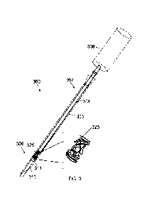
[0017] FIG. 3 illustrates aspects of an apparatus for making a marker
element,
according to various aspects of the present invention;
[0018] FIG. 4 illustrates aspects of an apparatus for making a marker
element,
according to various aspects of the present invention;
[0019] FIG. 5 provides a flow chart of a method for making a marker
element
within a marker delivery apparatus, according to various aspects of the
present
invention;
[0020] FIG. 6 provides a flow chart of a method for making a marker
element
within a marker delivery apparatus, according to various aspects of the
present
invention; and
[0021] FIG. 7 illustrates aspects of a kit for delivering a marker
element to a
tissue, according to various aspect of the present invention.
DETAILED DESCRIPTION
[0022] These and other features and advantages of this invention are
described in, or are apparent from, the following detailed description of
various
example aspects.
6
CA 02949832 2016-11-21
WO 2015/179667 PCT/US2015/032012
[0023] Referring to FIG. 1, in one aspect, the marker delivery apparatus
100
includes a tube 105 having a first end 106 and a second end 107. It should be
noted
that the terms "first end" and "second end" will be used consistently
throughout the
disclosure and claims to identify an end of an element (e.g., the wire 120,
the base
element 110, the force applicator 204, etc.) that is closest to the first end
106 or the
second end 107, respectively. The tube may include, for example, a needle
having a
lumen, a cannula, or a trocar of any type suitable known for delivering a
marker
element or other items (e.g., a surgical device, medicaments) to a tissue
site. In one
aspect, an outer diameter of the tube is about the same or less than a
diameter of a
biopsy site.
[0024] The tube 105 may have a handle member 115 at the second end 107
for holding the tube 105. In one aspect, the handle member 115 includes an
opening 116 in communication with the interior space of the tube 105, the
opening
116 being configured to receive a wire 120 in a longitudinal direction of the
tube 105.
As will be described in more detail below, the wire 120 may be compressed to
form a
marker element.
[0025] In one aspect, the wire has a suitable length, diameter,
malleability,
tensile strength, yield strength, elongation properties and breakage
properties to
undergo compression to make the marker element. For example, the wire may have
a length of about 1.5 inch to about 20 inch (e.g., 5 inch), a diameter of
about 0.001 to
0.100 inch (e.g., about 0.006 inch), a tensile strength of about 18,000 to
25,000 psi
(e.g., 21,000 psi), a yield strength of about 9,000 to 15,000 psi (e.g.,
12,000 psi), an
elongation at break of about 25% to 35% (e.g., 29%), and a breaking load of
about
7
CA 02949832 2016-11-21
WO 2015/179667 PCT/US2015/032012
250 to 300 grams (e.g., 270 grams). The wire may also be in accordance with
the
chemical section of the ASTM-F-72 standard for gold.
[0026] The marker element may be formed from a wire having a high
acoustic
impedance compared to the tissue site and, optionally, may be radio-opaque.
Suitable wire materials include, but are not limited to, biocompatible
materials, such
as gold, titanium, chromium, cobalt, stainless steel, silver, platinum,
tantalum,
palladium and alloys thereof. In one aspect, the wire may have a purity of
10K, 14K,
18K, 21K or 24K gold. Gold may be particularly be useful as a marker material
for
some applications of the technology because it is visible by imaging
techniques,
such as x-ray, ultrasound, or MRI, and is highly bio-compatible. Gold is also
useful
because it provides a smaller MRI artifact, which aids physicians in viewing
the area
directly around the marker. Other metals may have larger artifacts and may
obscure
areas directly around the marker. Additionally, composite materials, including
one or
more of the aforementioned metals and a polymer, for example,
polyetherketoneketone, polyethylene, polypropylene, polyurethane,
polytetrafluoro-
ethylene, polyvinyl-chloride, polyamides, and polycarbonate may also be used
to
form the compressible, malleable wire 120. In other aspects, the wire 120 may
include one or more of the aforementioned polymers.
[0027] In other aspects, the wire 120 may have a cross-section that is
circular,
ovular, rectangular, triangular, trapezoidal, or any other polygonal shape
(e.g., star-
shaped). The wire 120 may also be braided, twisted, flat or of any other shape
or
configuration suitable for compression within the tube to form a marker
element.
8
CA 02949832 2016-11-21
WO 2015/179667 PCT/US2015/032012
Moreover, the cross-section, shape and/or configuration of the wire 120 may be
selected to optimize bending of the wire and formation of the marker element.
[0028] A base element 110 may be configured for insertion into the first
end
106 of tube 105 as shown in FIG. 1. The base element 110 may be constructed of
any suitable material, for example, a polymer, a metal or a combination of the
two.
In one aspect, the base element 110 may include an end element 111 configured
to
seal the first end 106 of the tube 105 and to provide a base against which the
wire
120 is compressed. If an end element 111 is not incorporated, the base element
110
may be sized slightly smaller (e.g. about 0.0001 to about 0.001 inch) than the
inner
diameter of the tube 105, so that it is able to be slidably received within
the tube 105.
In another aspect, the base element 111 may comprise a soft material, such as
silicone, rubber, or other polymer that is configured to slightly deform
during
compression of the wire 120 and formation of the marker element.
[0029] A force applicator 204, (e.g., a rod), may be used to compress (or
crumple, for example) the wire 120 within the tube 105. An example of such a
force
applicator 204 is shown in FIG. 2. In one example aspect, the force applicator
204
may have a handle element 209 at a second end for gripping or holding the
force
applicator 204. The handle element 209 may also be in communication with an
electrically driven press (not shown), hydraulic mechanism (not shown) or
other
compression mechanism configured to move the force applicator 204 in and out
of
the inside portion of the tube 105, as would be readily understood by those of
skill in
the art. As will be described in more detail below, the force applicator 204
may be
configured to compress the wire 120 to a selected length of the tube, for
example, so
9
CA 02949832 2016-11-21
WO 2015/179667 PCT/US2015/032012
that the compressed wire 120 (i.e., the resulting marker element) is about 3
mm as
measured between the a second end of the base element 110, 111 and a first end
of
the force applicator 204, thereby forming the marker element. In various
aspects,
the force applicator 204 may be formed of a metal or a polymer material, or a
combination thereof. The force applicator 204 may need to have a sufficient
hardness to compress the wire 120 without breaking.
[0030] In another aspect, the force applicator 204 may have a similar
shape to
the tube 105, and the size of the force applicator 204 may be such that when
inserted into the tube 105, there is a clearance of about 0.0005 to about
0.003
inches, preferably about 0.001 to about 0.002 inches, between the outside
surface of
the force applicator 204 and the inside surface of the tube 205. For example,
if the
tube 105 is cylindrical and the force applicator 204 is cylindrical, the
diameter of the
force applicator 204 may also be about 0.001 to about 0.002 inches smaller
than the
inside diameter of the tube 105. If the tube 105 and force applicator 204 have
an
elliptical cross-section, for example, then the clearance between the outside
surface
of the force applicator 204 and the inside surface of the tube 105 may be
about
0.001 to about 0.002 inches. This clearance ensures adequate compression of
the
wire 120 and optimal formation of the marker, as will be further explained
below.
Moreover, the clearance should generally not be too small, or the force
applicator
204 may not be readily moveable within the tube 105. Also the force applicator
204
generally should not be too great, or it will not compress the wire 120 from
its second
end (e.g., the force applicator 204 may slip to one side or another of the
wire 120).
Therefore, the inventors have found that a force applicator 204 sized so that
there is
CA 02949832 2016-11-21
WO 2015/179667 PCT/US2015/032012
a clearance of about 0.001 to about 0.002 inches is particularly useful for
compression of the wire 120 for some applications of the technology.
[0031] In FIG. 3 the force applicator 304 is shown inserted into the tube
305
after compressing the wire to a predetermined length of the tube 305, so as to
form
the marker element 325. As will be appreciated by those of ordinary skill in
the art, a
marker element 325 formed in a particular tube 305 may differ from another
marker
element 325 formed in a different tube 305, even though the wire and tube may
be of
the same or similar size and material. Thus, because of 1) the mechanical
properties of each wire 120 used to form the marker element 325, 2) the
relative size
of the wire 120 to the tube 305, and 3) the physical placement or location of
the wire
120 within the tube 305 prior to compression, a first marker element formed in
a first
tube, may differ from a second marker element formed in a second tube. As will
be
appreciated by those skilled in the art, for example, a first wire will not
bend in
exactly the same manner as a second wire when undergoing compression by the
force applicator 304 in a first tube as compared to a second tube. For
example, if a
first wire is placed close to an inside surface of a first tube and a second
wire is
placed in the middle of a second tube, this placement will affect how the wire
bends.
It is an aspect of the present invention that such placement does not need to
be
controlled, which reduces the time and cost associated with forming a marker
element 325.
[0032] The marker element 325 depicted in FIG. 3 is just one example of
how
the wire 120 may bend from compression by the force applicator 304 to form the
marker 325. In one aspect, the first end of the wire 120 may initially coil
during
11
CA 02949832 2016-11-21
WO 2015/179667 PCT/US2015/032012
compression and at the end of compression, for example, the second end of the
wire
120 may be compressed flat. While multiple marker elements 325 formed using a
method and/or apparatus in accordance with aspects of the present invention
may
differ, all marker elements 325 (e.g., 325a, 325b, etc.) formed in respective
tubes
305 (e.g., 305a, 305b) may have common characteristics. For example, a marker
element 325 may be about 2 mm to about 5 mm in length, preferably about 3 mm
in
length, as measured between the second end of the base element 110, 111 (i.e.,
the
inside face of end element 111) and the first end of the force applicator 304.
More
specifically, the force applicator 304 may be sized so that it will stop
compression of
the wire when the first end of the force applicator 304 is at a predetermined
distance
from the second end of the base element 110.
[0033] A positive stop may be provided between the applicator and the
fixture.
In this case, the handle of the applicator may be sized such that it
encompasses or
partially encompasses the receiving element 406 and contacts the fixture so
that it
cannot be pushed down any further. At the point of contact, the applicator rod
may
be in the appropriate position to create a marker of the desired size.
[0034] A control mechanism, electronic or hydraulic, for example, may be
provided, where the travel of the applicator is monitored by a feedback loop,
and,
when the applicator travels the prescribed distance to create a marker of a
certain
size, the control mechanism stops the travel of the applicator and returns it
to the
home position.
12
CA 02949832 2016-11-21
WO 2015/179667 PCT/US2015/032012
[0035] Moreover, a total mass of wire used to form a particular marker
element 325 (e.g., 325a, 325b) may be the same or similar for each particular
marker element 325 formed by the method and apparatus of the present
invention.
For example, an 18 gauge, 18 karat gold wire may have a length of about 10
inches
and a 12 gauge, 18 karat gold wire may have a length of about 2.5 inches, the
total
mass of marker element 325 produced from each wire is approximately the same.
In
one example aspect, the total mass of wire received to form the marker element
may
be about 1 g to about 10 g (e.g., about 4 g).
[0036] In addition, the resulting marker element 325 may have a general
shape consistent with the inside shape of the tube 305. For example, in the
case of
a cylindrical tube, the resulting marker element 325 may be generally
cylindrical in
shape. It will be appreciated that during longitudinal compression, the wire
may
bend in a radial direction, as well. Thus, during compression, the wire may
exert a
force against the inside surface of the tube 305 so that the resulting marker
element
325 is shaped and sized to fit snuggly within the particular tube 305 and is
held in
place near the first end 306 of the tube 305. Thus, when the base element 310,
311
and force applicator 304 are removed, the marker element 325 may remain in
place.
For example, the friction force required to move the marker element 325 in the
tube
305 may be greater than the weight of the marker element 325, which prevents
undesired sliding of the marker element within the tube 305.
[0037] Another characteristic of the marker element 325 may be the
formation
of open spaces within the general structure as a result of the random bending
of the
wire. For example, as shown in FIG. 3, the wire may be compressed to form a
13
CA 02949832 2016-11-21
WO 2015/179667 PCT/US2015/032012
generally cylindrical structure having open spaces formed between the bends in
the
wire. Therefore, when implanted in a tissue, the open spaces of the marker
element
325 may be filled by growing tissue, which ensures the marker element 325 will
remain in place.
[0038] In other aspects, the size of tube 305 (e.g., length and diameter)
may
differ between one patient and another, depending, for example, on the type of
procedure, location of tissue extraction, size of the patient and/or weight of
the
patient. Therefore, the length and diameter of the force applicator 304 may
also
differ, depending on the circumstances. Nonetheless, the marker element 325
may
generally be about 2 mm to about 5 mm in length, preferably about 3 mm in
length,
and the force applicator 304 may be sized to have a clearance of about 0.0005
to
0.003 inch, preferably about 0.001 to 0.002 inches, between its outer surface
and the
inner surface of the tube 305. It should be noted that the depiction of the
force
applicator 304 in tube 305 in FIG. 3 is merely for illustrative purposes. In
one aspect,
the outside diameter of the force applicator 304 may be very proximally close
to the
inner surface of the tube 304, for example, when the clearance is 0.0005 to
0.003
inch. In addition, the resulting marker element 325 may have the same or
similar
characteristics to as described above.
[0039] In other aspects of the invention, a fixture 401 may be used to
aid in
the compression of the marker element, as shown in FIG. 4. A tube 405 may be
inserted into the fixture 400 having incorporated therein a base element (not
shown
in FIG. 4) that is movable in and out of the first end (not shown in FIG. 4)
of the tube
405 via an element 402, such as a set screw, located at a base of the fixture
400. In
14
CA 02949832 2016-11-21
WO 2015/179667 PCT/US2015/032012
one aspect, element 402 holds the base element in place. If the base of the
fixture
401 is removable for access to the base element. In some variations, the
height of
the base element may then be adjusted by loosening the screw and moving the
base
element up or down a certain amount. When the desired height is reached, the
screw may be tightened again, such as to hold the base element in place.
[0040] In an example aspect, the fixture 400 may be configured to hold
the
tube 405 vertically as shown in FIG. 4. Vertically orienting tube 405 may
provide for
easier manufacturing, for example, in that the first end of wire 120 may be
inserted
through the second end of tube 405, and then released, such that gravity pulls
wire
120 down until it contacts the base element. A horizontally oriented fixture
would not
provide similar manufacturing ease. The force applicator 404 may then be
inserted
into the tube 405 to compress the wire (not shown) and form the marker element
(not
shown). The fixture 400 may include extender elements 401, 403, for example,
that
may be affixed to the receiving element 406 of the fixture 400, where the
extender
elements 401, 403 are used to hold longer tubes 405. Consequently, longer
force
applicators 404 may also be used.
[0041] In another aspect, the fixture shown in FIG. 4 may create one
marker
element at a time; however, a larger scale fixture may also be used. A larger
scale
fixture may be configured to hold multiple tubes, for example. In another
example for
an automated process, the larger scale fixture may be moveable beneath a force
applicator or multiple force applicators. When aligned with a tube, the force
applicator(s) may be lowered to compress the corresponding wire(s) and then
raised
to remove the force applicator(s) from the tube(s). After compression in a
first tube,
CA 02949832 2016-11-21
WO 2015/179667 PCT/US2015/032012
the fixture may then translate one space, for example, so that a second tube
may be
aligned with the force applicator for compression.
[0042] It should be noted that the length of the force applicator 204,
304, 404
may be sized to stop compression at a predetermined length of the tube 105,
305,
405 to form the marker element (e.g., the force applicator may be shorter than
the
tube). In this instance, the base element 110, 111 may be sized to slide into
a first
end 106 of the tube at a (repeatable) predetermined length (e.g., so that
there is a
predetermined length between the end of the force applicator and the base
element).
[0043] Although the force applicator 304, 404 may be manually pushed into
tube 305, 405 using handle 309, 409 to form the marker element, in one aspect,
a
compression mechanism (e.g., an electrically driven press or hydraulic
mechanism)
may be used. In an automated process, a robot or other mechanism employed to
lower the force applicator, may be controlled based on, for example, the
lowering
rate of the force applicator and elapsed time, a detection sensor or sensors
configured to detect height, or by any other suitable means known to those of
skill in
the mechanical processing arts.
[0044] Aspects of a method of making a marker element 500 according to
the
present invention are described with reference to FIG. 5. The method 500 may
optionally include, at 505 providing a tube (e.g., tube 105, 305, 405 as
described in
reference to FIGs. 1, 3 and 4 above). In one aspect, at 505 providing the tube
comprises receiving the tube in a fixture (e.g., 400 of FIG. 4) for supporting
the tube.
The fixture may be configured to support the tube in a vertical orientation,
for
16
CA 02949832 2016-11-21
WO 2015/179667 PCT/US2015/032012
example, as shown in FIG. 4. In another aspect, the base element (e.g.,
element
110, 310 of FIGs. 1, 3) may be coupled to an element of the fixture.
[0045] The method may further include at 510 receiving a base element
(e.g.,
element 110, 310 of FIGs. 1, 3) in a first end (e.g., end 106, 306 of FIGs. 1,
3) of a
tube, where the base element seals the first end of the tube and provides a
base
against which the wire (e.g., wire120, 320 of FIGs. 1, 3) is compressed. The
base
element may be configured to position a second end of the wire at a
predetermined
position near the first end of the tube, for example.
[0046] At 515, the method includes receiving a wire in a second end of
the
tube, where the wire is as described above with reference to FIGs. 1 and 3,
for
example. The wire may be on a spool and inserted into the second end of the
tube
while still on the spool, for example. The wire may then be cut to a selected
length
so that the density of wire used to make, for example, a first marker element
and a
second marker element that is the same or very similar. The wire may also be
cut to
different lengths, for example, to create a first marker element and a second
marker
element having densities that are significantly different. In one aspect, the
spool may
be automated to dispense and cut the wire to a predetermined length. In
another
aspect, the wire may be cut to a selected length before insertion into the
tube. As
discussed with respect to FIG. 1, the wire may be malleable and comprise a
suitable
material resistant to foreign body reactions. In example aspects, the wire may
be
gold, and, particularly for some applications of the technology, annealed
gold.
17
CA 02949832 2016-11-21
WO 2015/179667 PCT/US2015/032012
[0047] At 520, the method includes applying a force to a second end of
the
wire using a force applicator, wherein the force compresses the wire in a
longitudinal
direction of the tube to a predetermined length of the tube to form the marker
element within the tube. In one aspect, the width or diameter of the force
applicator
may be less than an inner width or diameter of the tube so as to provide
clearance,
as discussed above with reference to FIGs. 1 and 3. In another aspect, the
width or
diameter of the force applicator may be greater than the width or diameter of
the
wire. Applying a force at 512 may further include one or more of moving a
device
coupled to the force applicator, activating an electrically driven mechanism
configured to move the force applicator, and/or activating a hydraulic
mechanism
configured to move the force applicator.
[0048] Aspects of a method of making or assembling a kit for marking a
tissue
are described with reference to FIG. 6. Like the method 500 of FIG. 5, method
600
of FIG. 6 includes providing a tube 605 (optionally), receiving a base element
in a
first end of the tube 610, receiving a wire in a second end of the tube 615,
applying a
force to the wire at the second end of the tube using a force applicator,
wherein the
force compresses the wire to a predetermined length of the tube to form the
marker
element within the tube 620, and removing the force applicator from the tube
625.
[0049] In other aspects, method 600 may include at 625 removing the base
element from the tube. In one aspect, after compression and removal of the
base
element, the marker element may remain fixed near the first end of the tube
such as
by a friction force greater than a weight of the marker element.
18
CA 02949832 2016-11-21
WO 2015/179667 PCT/US2015/032012
[0050] With reference to the method of FIG. 6 as applicable to the
example kit
of FIG. 7, at 630, the method 600 includes providing an actuator element
(e.g.,
element 719 of FIG. 7) receivable in the second end 707 of the tube 705. In
one
aspect, a first end of the actuator element 719 may form a sharp tip 718, like
a
needle or stylet, which may assist in moving the marker element 725 from the
tube
705 and into a tissue site (not shown). In another aspect, the tip may be flat
(not
shown). In yet another aspect, the actuator element, like the force applicator
(discussed above), is sized so that there is a clearance of about 0.0005 to
about
0.003 inch (e.g., about 0.001 to 0.002 inch) between the outer diameter of the
actuator element and the inner diameter of the tube. In addition, the tissue
site may
be or include the site of a biopsy or surgical incision.
[0051] In another aspect, method 600 as applied to the kit of FIG. 7 may
further include at packaging the actuator element 719, the tube 705 and the
marker
element 725 together in a sterile material 730 to form a kit 700. The sterile
material
730 may be any suitable material that is typically used for packaging sterile
equipment used in the medical field, for example.
[0052] While aspects of this invention have been described in conjunction
with
the example features outlined above, various alternatives, modifications,
variations,
improvements, and/or substantial equivalents, whether known or that are or may
be
presently unforeseen, may become apparent to those having at least ordinary
skill in
the art. Accordingly, the example aspects of the invention, as set forth
above, are
intended to be illustrative, not limiting. Various changes may be made without
departing from the spirit and thereof. Therefore, aspects of the invention are
19
CA 02949832 2016-11-21
WO 2015/179667
PCT/US2015/032012
intended to embrace all known or later-developed alternatives, modifications,
variations, improvements, and/or substantial equivalents.