Language selection

Search

Patent 2949941 Summary

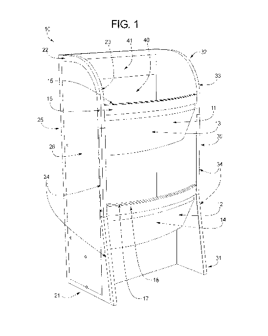
Third-party information liability

Some of the information on this Web page has been provided by external sources. The Government of Canada is not responsible for the accuracy, reliability or currency of the information supplied by external sources. Users wishing to rely upon this information should consult directly with the source of the information. Content provided by external sources is not subject to official languages, privacy and accessibility requirements.

Claims and Abstract availability

Any discrepancies in the text and image of the Claims and Abstract are due to differing posting times. Text of the Claims and Abstract are posted:

  • At the time the application is open to public inspection;
  • At the time of issue of the patent (grant).
(12) Patent Application: (11) CA 2949941
(54) English Title: STORAGE OR DISPLAY SYSTEM WITH A BIN
(54) French Title: SYSTEME DE STOCKAGE OU D'AFFICHAGE COMPRENANT UN BAC
Status: Deemed Abandoned and Beyond the Period of Reinstatement - Pending Response to Notice of Disregarded Communication
Bibliographic Data
(51) International Patent Classification (IPC):
  • A47F 05/00 (2006.01)
  • A47B 95/04 (2006.01)
(72) Inventors :
  • TAYLOR, CURTIS (United States of America)
  • MISENER, AARON (United States of America)
(73) Owners :
  • NESTEC S.A.
(71) Applicants :
  • NESTEC S.A. (Switzerland)
(74) Agent: BORDEN LADNER GERVAIS LLP
(74) Associate agent:
(45) Issued:
(86) PCT Filing Date: 2015-06-19
(87) Open to Public Inspection: 2015-12-23
Availability of licence: N/A
Dedicated to the Public: N/A
(25) Language of filing: English

Patent Cooperation Treaty (PCT): Yes
(86) PCT Filing Number: PCT/IB2015/054640
(87) International Publication Number: IB2015054640
(85) National Entry: 2016-11-22

(30) Application Priority Data:
Application No. Country/Territory Date
62/014,255 (United States of America) 2014-06-19

Abstracts

English Abstract

An improved storage and/or display system having one or more protection strips or guards.


French Abstract

L'invention concerne un système de stockage et/ou d'affichage amélioré comportant une ou plusieurs bandes de protection ou un/des moyens de protection.

Claims

Note: Claims are shown in the official language in which they were submitted.

4
CLAIMS
The invention is claimed as follows;
1. A system for storage and/or display, the system comprising:
a first side wall comprising a first front edge, a first outer face, and a
first inner face;
a second side wall comprising a second front edge, a second outer face, and a
second
inner fact, the second inner face positioned to face the first inner face;
a back wall extending between the first side wall and the second side wall;
a first bin extending forward from the back wall to be positioned between the
first and
second side walls, extending from the first inner face to the second inner
face, and comprising a
first top edge; and
a protective component connected to at least one other component selected from
the
group consisting of the first front edge, the second front edge, first outer
face, the second outer
face, the back wall, and the first top edge.
2. The system of Claim 1, wherein the protective component is a protection
strip or
guard connected to at least one of the first front edge or the second front
edge.
3. The system of Claim 1, wherein the protective component is a protection
strip or
guard connected to the first top edge of the first bin,
4. The system of Claim 3, wherein the first top edge is arcuate.
5. The system of Claim 1, wherein the protective component is a protective
panel
connected to at least one of the first outer face or the second outer face,
6. The system of Claim 1, wherein the protective component is a protective
panel
connected to the back wall.
7. The system of Claim 1, wherein the protective component comprises
rubber.

5
8. The system of Claim 1, wherein the protective component comprises
plastic.
9. The system of Claim 1, wherein the protective component comprises metal.
10. The system of Claim 1, wherein the first side wall has a width that is
a distance
from the back wall to the first front edge, the first side wall comprises a
lower portion positioned
at least partially beneath the first bin and an upper portion positioned at
least partially above the
first bin., and the lower portion is angled relative to the upper portion such
that the width of the
first side wall is greater at a lower edge of the lower portion relative, to
the width of the upper
portion,
11. The system of Claim 10, wherein the second side wall has a width that
is a
distance from the back wall to the second front edge, the second side wall
comprises a lower
portion positioned at least partially beneath the first bin and an upper
portion positioned at least
partially above the first bin, and the lower portion is angled relative to the
upper portion such that
the width of the second side wall is greater at a lower edge of the lower
portion relative to the
width of the upper portion.
12. The system of Claim 10, wherein the protective component is connected
to the
upper portion and the lower portion.
13. The system of Claim 1, wherein the protective component is connected by
adhesive to the at least one other component.
14. The system of Claim 1, wherein the protective component is connected by
rivets
to the at least one other component,
15. The system of Claim 1, wherein the protective component is connected
by screws
to the at least one other component.
16. The system of Claim 1, wherein the protective component is connected by
bolts to

6
the at least one other component.
17. The system of Claim 1, wherein the protective component is connected by
snap
connection to the at least one other component.
18. The system of Claim 1, wherein the protective component is connected by
slot fit
connection to the at least one other component.
19. A .method comprising:
storing an item in an apparatus comprising (i) a first side wall comprising a
first front
edge, a first outer face, and a first inner face; (ii) a second side wall
comprising a second front
edge, a second outer face, and a second inner face, the second inner face
positioned to face the
first inner face; (iii) a back wall extending, between the first side wall and
the second side wall;
(iv) a first bin extending forward from the back wall to be positioned between
the first and
second side walls, extending from the first inner face to the second inner
face, and comprising a
first top edge; and (v) a protective component connected to at least one other
component selected
from the group consisting of the first front edge, the second front edge,
first outer face, the
second outer face, the back wall, and the first top edge,
20. A method comprising:
displaying an item on an apparatus comprising (i) a first side wall comprising
a first front
edge, a first outer face, and a first inner face; (ii) a second side wall
comprising a second front
edge, a second outer face, and a second inner face, the second inner face
positioned to face the
first inner face; (iii) a back wall extending between the first side wall and
the second side wall;
(iv) a first bin extending forward from the back wall to be positioned
between the first and
second side walla, extending from the first inner face to the second. inner
face, and comprising a
first top edge; and (v) a protective component connected to at least one other
component selected
from the group consisting of the first front edge, the second front edge,
first outer face, the
second outer face, the back wall, and the first top edge.

Description

Note: Descriptions are shown in the official language in which they were submitted.


CA 02949941 2016-11-22
WO 2015/193857
PCT/1B2015/054640
1
171TLE
STORAGE OR DISPLAY SYSTEM WITH A BIN
PRIORITY CLAIM
[0001] The present application claims priority to U.S. Provisional Patent
Application No.
62/014,255, filed on June 19, 2014, the entire contents of which are
incorporated herein by
reference.
BACKGROUND
[0002] The present invention is a container and, more particularly, a
storage and/or display
system,
BRIEF DESCRIPTION OF THE FIGURES
[0003] Fig. 1 shows a front perspective view of an embodiment of a storage
and/or display
system provided by the present disclosure.
[0004] Fig. 2 shows a side perspective view of an, embodiment of a storage
and/or display
system provided by the present disclosure.
[0005] Fig. 3 shows a front perspective view of an embodiment of a storage
and/or display
.system provided by the present disclosure.
DETAILED DESCRIPTION
[0006] Referring now to Figs. 1-3, there is one non-limiting embodiment of
the storage
andior display system 10 in accordance with the present invention. Figs. 1-3
illustrate the
storage and/or display system 10 having two storage bins 11,12; however, it
can be appreciated
that the storage andlor display system 10 can have more storage bins than the
two storage bins
11,12. The height and width of the storage and/or display system 10 are non-
limiting. The
materials used to form the storage and/or display system 10 are non-limiting.
[0007] The front bases :21,31 of the storage andJor display system 10 is
illustrated as being
wider than the tops 22,32 of the storage and/or display system 10 so as to
provide additional
stability to the storage and/or display system 10; however, this is not
required. The faces 13,14
of the bins 11,12 is arcuate or curved; however, this is not required. The
front edges 23,33 of the
storage and/or display system 10 can optionally include protection strips or
guards 24,34 to

CA 02949941 2016-11-22
WO 2015/193857 PCT/1B2015/054640
2
inhibit or prevent damage to the storage and/or display system 10; however,
this is not required.
The protection strips or guards 24,34 can be made of a durable material such
as wood, metal,
plastic, rubber, etc. The protection strips or guards 24,34 can be connected
to the front edges
23,33 by various means (e.g., adhesive, rivets, screws, bolts, snap
connection, slot fit connection,
etc.). One or both sides 25,35 of the storage and/or display system 10 can
optionally include a
protective panel 26 to inhibit or prevent damage to the storage and/or display
system 10;
however, this is not required. The protective panel 26 can be made of a
durable material such as
wood, metal, plastic, rubber, etc. The protective panel 26 can be connected to
the side by various
means (e.g., adhesive., rivets, screws, bolts, snap connection, slot fit
connection, etc.). The top
edges 15,16 of the faces 13,14 of one or more of the bins 11,12 can include a
protection strip or
guard 17,18 . The protection strip or guard 17,18 can be made of a durable
material such as
wood, metal, plastic, rubber, etc. The protection strip or guard 17,18 can be
connected to the top
edges 15,16 by various means (ergõ adhesive, rivets, screws, bolts, snap
connection, slot fit
connection, etc.). The back face 40 of the one or more of the bins 11,12 can
include a protection
panel 41. The protection panel 41. can be made of a durable material such as
wood, metal,
plastic, rubber, etc. The protection panel 41 can be connected to the back
face 40 by various
means (e.g.,. adhesive,..rivets, screws, bolts, snap connection, slot fit
connection, etc.).
[0008] It will thus be seen that the objects set forth above, among those
made apparent from
the preceding description, are efficiently attained, and since certain changes
may be made in the
constructions set forth without departing from the spirit and scope of the
invention, it is intended
that all matter contained in the above description and shown in the
accompanying drawings shall
be interpreted as illustrative and not in a limiting sense. The invention has
been described with
reference to preferred and alternate embodiments. Modifications and
alterations will become
apparent to those skilled, in the art upon reading and understanding the
detailed discussion of the
invention provided herein. This invention is intended to include all such
modifications and
alterations insofar as they come within the scope of the present invention. It
is also to be
understood that the following claims are intended to cover all of the generic
and specific features
of the invention herein described and all statements of the scope of the
invention, which, as a
matter of language, might be said to fall therebetween. The invention has been
described with

CA 02949941 2016-11-22
WO 2015/193857
PCT/1B2015/054640
3
reference to the preferred embodiments.. These and other modifications of the
preferred
embodiments as well as other embodiments of the invention will he obvious from
the disclosure
herein, whereby the foregoing descriptive matter is to be interpreted merely
as illustrative of the
invention and not as a limitation. It is intended to include all such
modifications and alterations
insofar as they come within the scope of the appended claims,

Representative Drawing
A single figure which represents the drawing illustrating the invention.
Administrative Status

2024-08-01:As part of the Next Generation Patents (NGP) transition, the Canadian Patents Database (CPD) now contains a more detailed Event History, which replicates the Event Log of our new back-office solution.

Please note that "Inactive:" events refers to events no longer in use in our new back-office solution.

For a clearer understanding of the status of the application/patent presented on this page, the site Disclaimer , as well as the definitions for Patent , Event History , Maintenance Fee  and Payment History  should be consulted.

Event History

Description Date
Application Not Reinstated by Deadline 2019-06-19
Time Limit for Reversal Expired 2019-06-19
Deemed Abandoned - Failure to Respond to Maintenance Fee Notice 2018-06-19
Inactive: Cover page published 2017-01-27
Inactive: First IPC assigned 2017-01-24
Inactive: Notice - National entry - No RFE 2016-12-05
Inactive: IPC assigned 2016-11-30
Application Received - PCT 2016-11-30
National Entry Requirements Determined Compliant 2016-11-22
Application Published (Open to Public Inspection) 2015-12-23

Abandonment History

Abandonment Date Reason Reinstatement Date
2018-06-19

Maintenance Fee

The last payment was received on 2017-05-24

Note : If the full payment has not been received on or before the date indicated, a further fee may be required which may be one of the following

  • the reinstatement fee;
  • the late payment fee; or
  • additional fee to reverse deemed expiry.

Patent fees are adjusted on the 1st of January every year. The amounts above are the current amounts if received by December 31 of the current year.
Please refer to the CIPO Patent Fees web page to see all current fee amounts.

Fee History

Fee Type Anniversary Year Due Date Paid Date
Basic national fee - standard 2016-11-22
MF (application, 2nd anniv.) - standard 02 2017-06-19 2017-05-24
Owners on Record

Note: Records showing the ownership history in alphabetical order.

Current Owners on Record
NESTEC S.A.
Past Owners on Record
AARON MISENER
CURTIS TAYLOR
Past Owners that do not appear in the "Owners on Record" listing will appear in other documentation within the application.
Documents

To view selected files, please enter reCAPTCHA code :


To view images, click a link in the Document Description column. To download the documents, select one or more checkboxes in the first column and then click the "Download Selected in PDF format (Zip Archive)" or the "Download Selected as Single PDF" button.

List of published and non-published patent-specific documents on the CPD .

If you have any difficulty accessing content, you can call the Client Service Centre at 1-866-997-1936 or send them an e-mail at CIPO Client Service Centre.


Document
Description 
Date
(yyyy-mm-dd) 
Number of pages   Size of Image (KB) 
Drawings 2016-11-21 3 78
Description 2016-11-21 3 166
Claims 2016-11-21 3 172
Abstract 2016-11-21 1 54
Representative drawing 2016-11-21 1 26
Courtesy - Abandonment Letter (Maintenance Fee) 2018-07-30 1 173
Notice of National Entry 2016-12-04 1 192
Reminder of maintenance fee due 2017-02-20 1 111
National entry request 2016-11-21 5 97
International search report 2016-11-21 3 68