Note: Descriptions are shown in the official language in which they were submitted.
CA 02949999 2016-11-22
WO 2016/069481 PCT/US2015/057386
PIVOTING LOAD-BEARING ASSEMBLY WITH FORCE SENSOR
TECHNICAL FIELD
[0001] The present invention relates to a pivoting load-bearing assembly
including a force sensor
arranged to measure a force in a particular direction, for example, to measure
a clamping force in
a load clamp for a lift truck, such as a carton clamp for use in handling
large household appliances
packed in corrugated cardboard cartons, or a paper roll clamp for handling
large paper rolls in
warehouses.
[0002] Lift trucks used for handling goods in warehouses may be equipped with
specialized load
clamping attachments intended to grip various types of loads securely. A lift
truck may have a
specialized paper roll clamp or a carton clamp including a pair of upright
generally planar clamp
arm assemblies extending forward from the lift truck and supporting generally
parallel, opposed
clamp pads. The clamp arms of load clamps are movable toward or away from each
other
laterally of the lift truck in order to grip or release a load.
[0003] As for carton clamps, while most cartons or similar containers have
parallel upright sides,
because of the nature of the goods inside the carton and other packing
material within the outer
skin of a carton, while it is generally desired to provide an even clamp force
distribution, that may
be difficult to achieve because of various mechanical factors. In some
situations, it may be
desirable to provide pressure against the exterior of a carton of a certain
type in an uneven
distribution, such as by providing greater pressure near the bottom of a
carton and lesser
pressure near the top of the part of the carton engaged by the clamp arm
assembly. Similarly, it
may be desirable to provide a certain distribution of clamping pressure on the
other types of loads
such as paper rolls. For some loads, such as large tires, it may be important
to know the total
force exerted by a load clamp. In these and other situations, it would be
useful to know how
much pressure is actually applied to a load as it is being grasped. While it
has been known to
calibrate lift trucks and control force by controlling hydraulic pressure, it
is desired to have an
actual clamping force measurement available during operation.
BACKGROUND ART
[0004] It is desirable for the clamp pad or clamp pads of a carton clamp to be
free to at least a
small extent, in order to accommodate clamp arm deflection and conform better
to the shape of a
carton and, to some extent, the contents of the carton. This capability is
addressed in prior art
Ehmann (U.S. Patent Nos. 2,681,162 and 2,684,387), Link (U.S. Patent No.
3,643,827), Farmer
(U.S. Patent No. 4,145,866), and Farmer, etal. (U.S. Patent Nos. 2,844,403 and
3,145,866), for
example, which disclose clamp pads mounted on carton clamp arms in ways which
allow a small
amount of articulation.
-1 -
CA 02949999 2016-11-22
WO 2016/069481 PCT/US2015/057386
[0005] Dosso et al. (U.S. Patent No. 8,517,440) discloses a lift truck
clamping attachment for
handling cartons in which clamping pads are mounted so as to be adjusted so
that the pressure
provided by the clamp pads provides a desired distribution of the clamping
pressure on the
packages to be hoisted and transported.
[0006] It is known that strain gauges can be incorporated in large shackle
pins or pivot pins or
axles supporting, for example, sheaves for load-carrying cables of cranes, to
provide electrical
signals representative of a load to which such a shackle pin or axle is
subjected, but use of such a
strain gauge arrangement in a smaller pivot pin or axle may not be practical,
and is quite costly,
may require greater manufacturing precision than is desirable in the fit of
such a pin to a set of
bores in which the pin is to located, and may compromise the strength of the
pivot pin in
situations where relatively small forces are to be used yet are desired to be
measured accurately,
Additionally, such load pins are not well adapted to use in situations where
bending forces in
other than the direction of interest may be applied to such pins.
[0007] It is therefore desired to have a pivoting load-carrying assembly
including an
arrangement in which a force exerted in a particular direction by the load-
carrying assembly can
be measured in an isolated manner.
SUMMARY OF INVENTION
[0008] As disclosed herein, a sensing device is provided in connection with at
least one and
advantageously more than one of a plurality of pivoting load-bearing
assemblies such as clamp
pad support assemblies to measure the force exerted in a particular direction
by a particular
clamp pad support assembly. Force values can be considered as a basis for
adjustment of a
clamp pad support assembly or particular ones of a set of them. In some
embodiments of the
pivoting load-bearing assembly, an adjustment of a radial distance between a
pivot axis and the
attachment of a clamp pad or the like may be provided.
[0009] As one aspect of the present invention, a mounting assembly for a load-
clamping
member is provided in which there is a pivoting support assembly including a
bearing block and a
pivot pin extending through the bearing block; a support member arranged to
provide support for
the pivoting support assembly in an axial direction and to transmit a clamping
force in a radial
clamping-force direction with respect to the pivot pin; a clamping-force
isolating arrangement in
the pivoting support assembly arranged to isolate and transmit clamping force
from the support
member to the pivoting support assembly in said clamping-force direction
separately from
providing support in the axial direction; and a force sensor in the pivoting
support assembly
located so as to measure the clamping force and arranged to provide a signal
representative of
the clamping force.
= 2 -
CA 02949999 2016-11-22
WO 2016/069481 PCT/US2015/057386
[0010] As another aspect, there is provided a pivoting load-bearing assembly
including a force-
measuring sensor, comprising a pivoting support assembly including a bearing
block and a pivot
pin extending through the bearing block; a support member arranged to provide
support for the
pivoting support assembly and to transmit force in a radial direction with
respect to the pivot pin
-- to the pivoting support assembly, the pivoting support assembly being
located in a receptacle
defined in the support member and being fastened to the support member by the
pivot pin; a
force-isolating arrangement, arranged to isolate and transmit the force in a
radial direction from
the support member to the pivoting support assembly separately from providing
support to the
pivoting support assembly; and a force sensor located in the pivoting support
assembly, between
-- the bearing block and the pivot pin, so as to measure said force in a
radial direction and to
provide a signal representative of the amplitude of that force.
[0011] Also provided is a load grasping assembly for a lift truck, comprising
a clamp arm adapted
to be mounted on a lift truck; a clamp pad; a pivoting clamp pad support
assembly carried by the
clamp arm and connected to and supporting the clamp pad, the clamp pad support
assembly
-- being mounted so as to pivot through a limited angle with respect to the
clamp arm and including
a force sensor mounted in such a way as to sense in isolation a force exerted
by the pivoting
clamp pad support assembly in a predetermined direction while the load
grasping assembly grasps
a load, and to provide a an electrical signal representative of a magnitude of
the force exerted in
the predetermined direction.
-- [0012] As yet a further aspect, a method is provided for adjusting a load
grasping assembly for a
lift truck equipped with a load grasping assembly including a clamp arm, a
clamp pad mounted to
the clamp arm through a pivoting clamp pad support assembly, and a force
sensor included in the
clamp pad support assembly, the method comprising providing a test load body
having a
predetermined configuration, grasping the test load body with the load
grasping assembly,
-- obtaining a signal from the force sensor representative of the force
exerted in a predetermined
direction by the pivoting clamp pad support assembly, determining from the
signal a magnitude of
a grasping force exerted in the predetermined direction by the pivoting clamp
pad support
assembly while grasping the test load body, and in response, adjusting a
clamping force applied
by the clamp arm.
-- [0013] A method is also provided of utilizing signals from each of a
plurality of force sensors in
respective ones of a group of pivoting clamp pad support assemblies supporting
a clamp pad to
determine whether the distribution of forces exerted through the pivoting
clamp pad support
assemblies is appropriate, and, in response adjusting a distance adjustment
included in at least
one of the pivoting clamp pad support assemblies and thereby adjusting the
distribution of forces
-- exerted through the plurality of clamp pad support assemblies to support
the clamp pad.
CA 02949999 2016-11-22
WO 2016/069481 PCT/US2015/057386
[0014] The foregoing and other features of the invention will be more readily
understood upon
consideration of the following detailed description of the invention, taken in
conjunction with the
accompanying drawings.
BRIEF DESCRIPTION OF DRAWINGS
-- [0on] FIG. 1 is a side elevational view of a clamp arm assembly for a lift
truck, including clamp
pads mounted on the clamp arm assembly with the use of adjustable pivoting
clamp pad support
assemblies.
[0016] FIG. 2 is a sectional view of one of the adjustable pivot assemblies
included in the clamp
arm assembly, taken along line 2-2 in FIG. 1, at an enlarged scale.
-- [0017] FIG. 3 is a sectional view of the adjustable pivot assembly shown in
FIG. 2, taken along
line 3-3 in FIG. 1, at an enlarged scale.
[ocas] FIG. 4 is an exploded isometric view of the clamp arm and clamp pad
assembly shown in
FIG. 1, taken from the upper left front.
[0019] FIG. 5 is an exploded isometric view of a portion of FIG. 4 including
one of the adjustable
-- pivoting clamp pad support assemblies, at an enlarged scale.
[0020] FIG. 6 is an exploded isometric view of a bearing block and associated
parts of an
adjustable pivoting clamp pad support assembly such as the ones shown in FIGS.
1, 3, and 5.
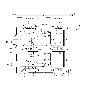
[0021] FIG. 7 is a diagrammatical view of a system incorporating the
adjustable pivoting clamp
pad support assemblies.
-- [0022] FIG. 8 is an isometric view of a clamp assembly and a test body
useful for checking the
adjustment of the pivoting clamp pad support assemblies.
[0023] FIG. 9 is an isometric view of a carton clamp assembly together with a
set of cams
equipped with force sensors, used to calibrate the force sensors in the
adjustable pivoting clamp
pad support assemblies.
-- [0024] FIG. 10 is a perspective view of a layer picker clamp fork lift
attachment incorporating the
adjustable clamp pad support assemblies, shown grasping a selected number of
layers of a stack
of cartons of canned goods.
[0025] FIG. 11 is a perspective view of one clamp arm assembly for a layer
picker such as that
shown in FIG. 10.
-- [0026] FIG. 12 is an elevational view of the clamp arm assembly shown in
FIG. 11.
CA 02949999 2016-11-22
WO 2016/069481 PCT/US2015/057386
[0027] FIG. 13 is a sectional view taken along line 13-13 of FIG. 12, showing
the locations of
adjustable pivoting clamp pad support assemblies.
[0028] FIG. 14 is an exploded isometric view of a portion of FIG. 4 including
an alternative
embodiment of one of the adjustable pivoting clamp pad support assemblies, at
an enlarged scale.
[0029] FIG. 15 is a sectional view of one of the adjustable pivot assemblies
of alternate
construction included in the clamp arm assembly, taken along line 2-2 in FIG.
1, at an enlarged
scale.
[0030] FIG. 16 is a perspective view of the bearing block shown in FIG. 14,
showing cavities in
which strain gauges are mounted in the bearing block.
[0031] FIG. 17 is a top plan view of the bearing block of FIG. 14.
[0032] FIG. 18 is an elevation view of bearing block shown in FIG. 14.
[0033] FIG. 19 is a bottom plan view of the bearing block shown in FIG. 14
[0034] FIG. 20 is a sectional view, taken along line 20-20 in FIG. 18, showing
the arrangement of
strain gauges and interconnection with an integrated circuit arranged to
receive information from
the strain gauges.
[0035] FIG. 21 is a sectional view taken along line 21-21 of FIG. 17, showing
strain gages
attached to a surface of a measurement portion of the bearing block defined by
slots in the
bearing block and blind cavities in the sides of the bearing block.
DESCRIPTION OF EMBODIMENTS
[0036] Referring first to FIG. 1 of the drawings, in a load clamp assembly
that includes one
embodiment of the subject matter disclosed herein a carton clamp arm assembly
10 for a lift truck
includes transversely oriented horizontal members 12 adapted to be attached to
a front of a lift
truck (not shown), to permit the clamp arm assembly 10 to move transversely
with respect to the
lift truck, so that an opposed pair of such clamp arm assemblies 10 can move
toward or away
from each other to grip or release a load. Carried on the transverse members
12 is a clamp arm
14 that extends forward from the lift truck on which the clamp arm assembly 10
is mounted for
use. A load stabilizer 16 is mounted on the outer ends 18 of the clamp arm 14,
attached to the
outer ends 18 by coaxial pins 20 defining a substantially vertical pivot axis
of a hinge-like
connection. The stabilizer 16 thus can pivot about the coaxial pins 20, to
allow for deflection of
the clamp arm 14 or misalignment of a package to be gripped. The stabilizer 16
may be a
substantial steel member with a generally vertical central trunk portion and
respective sets of
multiple horizontal finger-like members 24 extending forwardly and rearwardly
from the trunk.
_
CA 02949999 2016-11-22
WO 2016/069481 PCT/US2015/057386
While three finger-like members 24 are shown in each direction here, there may
be two to five
finger-like members in various applications.
[0037] A load-contact pad, such as a carton clamp pad, may be a unitary member
(not shown)
or may, as shown, have the form of two large generally rectangular and
substantially flat load-
contact pad members 28 and 30 of a split load-contact pad. The load-contact
pad members 28
and 30 are carried respectively on the rearwardly-extending and forwardly-
extending finger-like
horizontal members 24 of the load stabilizer 16. Each of the load-contact or
carton clamp pad
members 28 and 30 is attached to the load stabilizer 16 by three adjustable
pivoting clamp pad
support assemblies 32, also called adjustable pivot assemblies, each of which
is mounted within a
receptacle 34 defined by a respective one of the finger-like horizontal
members 24. Each of the
receptacles 34 may be an opening extending through the respective finger-like
portion 24 of the
stabilizer 16.
[0038] Referring also to FIGS. 2, 3, and 4, a spring 22 is mounted on one of
the finger-like
portions 24 of the load stabilizer 16 and presses against an inner face of the
clamp arm 14,
tending to rotate the load stabilizer 16 about the coaxial pins 20, while a
pair of stop members 26
mounted on the clamp arm 14 limit angular movement of the load stabilizer 16
to a slightly toed-
out attitude.
[0039] For each of the separate carton clamp pad members 28 and 30 a pivot
axis is defined by
respective pivot pins 36 extending vertically through coaxially aligned bores
38 in the respective
finger-like members 24 supporting the clamp pad 28 or 30 and securing the
respective adjustable
pivoting clamp pad support assemblies 32 in the receptacles 34.
[0040] As shown best in FIG. 5, each receptacle 34 may include a pair of
opposed upper and
lower horizontal bearing faces 40 between which a respective adjustable
pivoting clamp pad
support assembly 32 is located, and the bores 38 for the pivot pins 36 extend
through the bearing
faces 40.
[0041] Referring also to FIG. 6, each adjustable pivoting clamp pad support
assembly 32 includes
a bearing block 42 defining a pivot pin bore 44 to receive a pivot pin 36. A
pair of threaded bores
46 extends through a flat base or inner face 48 of the bearing block 42 in a
direction
perpendicular to the axis of the pin bore 44. An adjustment collar 50, which
has external threads
and which may have a portion shaped to be engaged by a wrench, is threaded
into each of the
bores 46 as may be seen in FIG. 2 and acts as a positioning member, as is
described below.
[0042] The pressing, or grasping pressure forces exerted inwardly by the
pivoting support
assemblies 32 urging the clamp pads 28 and 30 toward each other are carried
from each finger-
like horizontal member 24 of the clamp arm 14 and transmitted by the bores 38
and the
- 6 -
respective pivot pin 36. The pressing, or clamping, force is isolated by a
clamping-force isolating
subassembly 51 and is transmitted from each pivot pin 36 to a load tube 52
fitted in the pin bore 44
of the bearing block 42. The load tube 52 fits snugly but rotatably about the
pivot pin 36. A central
portion 56 of the load tube 52 fits within the pin bore 44 of the bearing
block 42 and nearly in contact
with an interior surface of the pin bore 44, and is located and oriented so as
to receive a fastener
such as the screw 54 in a small hole 58 that may be provided in the outer
surface of the central
portion 56 to keep the load tube 52 in its intended location and orientation
in the bearing block 42.
The load tube is still free, however, to move radially a small distance within
the bore 44 as will be
explained presently. Outer end portions 60 of the load tube 52, extending from
the central portion 56
toward the upper and lower faces 62 of the bearing block 42, are slightly
smaller in exterior diameter
64 than the interior diameter 66 of the pin bore 44, to provide a radial space
between the end
portions 60 and the interior of the pin bore 44, where the pivot pin 36 and
the load tube 52 may flex
under load without bearing on the interior surface of the pin bore 44. It will
be understood that the
load tube 52 might instead be of a constant size along its end portions 60 and
central portion 56, in
which case the interior diameter of the pin bore 44 surrounding the end
portions 60 could be larger to
provide radial clearance around the load tube 52.
[0043] A cavity 70, which may be cylindrical, extends into the bearing block
42 from the outer face
48 and intersects with the pin bore 44. A central axis of the cavity 70 is
oriented in the direction of
forces that it is desired to measure, and the cavity 70 needs to extend deeply
enough so that all the
forces exerted in the direction of interest are carried through the central
portion 56 of the load tube
52 to the plunger 72. At the same time, the cavity 70 needs to be shallow
enough to leave the
central section 56 of the load tube 52 able to receive forces in directions
other than along the central
axis of the cavity 70, so that those forces can be carried from the bearing
block 42 to the finger 24 of
the load stabilizer 16 or an equivalent member of a load clamp assembly of
another type.
[0044] A plunger 72 is fitted slidably within the cavity 70 and may have a
concave cylindrical inner
end surface 74 that fits against and conforms to the shape of the exterior
surface of the central part
56 of the load tube 52, so that inwardly-directed, load-grasping forces of the
respective fingerlike
member 24 are carried through the pivot pin 36 and the central part 56 of the
load tube 52 and are
applied to the plunger 72.
[0045] A force-transmitting outer end 76 of the plunger 72 has a contact
surface 78 which may have
a concave, large-radius, spherical shape and which may be surrounded by a
shallow rim 80.
[0046] A button-like force-sensing or load cell 82 may have a centrally
located contact portion
including a contact face 84 that may have a large radius convex spherical
contact surface that
corresponds with the shape of the contact surface 78, and that rests against
and may be centered
- 7 -
CA 2949999 2018-05-23
CA 02949999 2016-11-22
WO 2016/069481 PCT/US2015/057386
on the contact surface 78 of the plunger 72, while the load cell 82 is held in
a central location by
the rim 80. An oppositely-located base surface 86 of the load cell 82 rests
against an interior face
of a retainer plate 88 that is fastened to the inner face 48 of the bearing
block 42 by suitable
fasteners such as screws 90 extending through corresponding holes in the
retainer plate 88 into
-- respective threaded bores in the inner face 48 of the bearing block 40. A
shim 92 may be
provided in an appropriate thickness to establish sufficient space for the
load cell 82, yet assure
that the retainer plate 88 has positive contact with and through the load cell
82, the plunger 72,
and the central part 56 of the load tube 52 to the interior surface of the pin
bore 44, so that
forces directed inwardly, in a clamping direction, by the pivot pin 36 are
carried in isolation to the
-- bearing block 42 through the load tube 52, the plunger 72, the load cell
82, and the retainer plate
88, and can thus be sensed by the load cell 82. At the same time, however, the
plunger 72 is
intended to ensure that only the compressive load-clamping forces are
transmitted to the load cell
82, while forces in other directions, such as load-lifting vertical forces,
are carried to the bearing
surfaces 40 through the upper and lower faces 62 of the bearing block 42.
Thus, the load cell 82
-- will measure only forces in the direction in which the plunger 72 is free
to move in the cavity 70.
[0047] The load cell 82 may be a subminiature industrial compression load cell
available from
various sources, such as OMEGA Engineering, Inc., of Stamford, Connecticut.
One acceptable
load cell has a diameter 94 of about 19 mm and a thickness or height 96 of
about 6.5 mm and
may be obtained in an appropriate capacity, depending upon the clamping force
desired to be
-- applied. A load cell 82 having a capacity of 2230 N, for example, may be
used, or a load cell
which has a similar size and a capacity of, for example, 4450 N may also be
used. A signal
conductor 98, including a suitable wire or wires, extends from the load cell
and passes through an
opening 100 provided through the bearing block 42 to carry an electrical
signal representative of
the pressure exerted on the load cell 82 by the retainer plate 88 and the
plunger 72 when the
-- clamp arm assembly 10 is exerting inwardly directed clamping force upon a
load. The signal
conductor 98 for the type of load cell 82 described above, for example,
includes a pair of
excitation wires and a pair of signal conducting wires.
[0048] A flat spacer plate 104, which may have a shape similar to that of the
outer face 48 of the
bearing block 42, defines a pair of bores 106 that are coaxially aligned with
the bores 46 in the
-- bearing block 42. Fasteners such as flat head screws 108 may be countersunk
in and extend
through a supporting plate portion 110 of the clamp pad 28 or 30, through the
bores 106 in the
spacer plate 104, and be engaged in threaded bores 112 defined by the collars
50, holding the
spacer plate 104 tightly against the inner ends 120 of the collars 20. A lock-
washer 114 and a self
locking nut 116 may be provided on the flat head screw 108 and tightened
against_ the collar 50 to
-- retain the screw 108 with the clamp pad 28 or 30 held tightly against the
spacer plate 104 as
shown in FIG. 2 and to keep the spacer plate 104 from moving with respect to
the collar 50. The
- 8 -
CA 02949999 2016-11-22
WO 2016/069481 PCT/US2015/057386
spacer plate 104 defines an opening 118 somewhat larger than the retainer
plate 88, so that the
spacer plate 104 can be close to or rest flush against the face 48 of the
bearing block 42, with the
retainer plate 88 in the opening 118.
[0049] As shown in FIG. 2, an inner end 120 of the adjustment collar 50
extends proud of the
outer face 48 of the bearing block 42, and keeps the spacer plate 104 an
adjustable distance 122
away from the inner face 48 of the bearing block 42. Thus, as shown in FIG. 2,
a radial distance
124 between the axis of the pivot pin 36 and the support plate 110 of the
clamp pad 30 is defined
by the location of the spacer plate 104 against the inner end 120.
[0050] As shown best in FIGS. 2, 3, and 5, and also in an enlarged, exploded
view in FIG. 6, with
the adjustable pivoting clamp pad support assemblies 32 all assembled as is
the one shown in
FIG. 2, both of the clamp pad members 28 and 30 are parallel with the central
axes defined by
the pivot pin bores 38 and pin bores 44 and thus are positioned so as to
provide equal pressure
along the entire height of the respective clamp pad 28 or 30 against a
vertical side of a carton to
be gripped by the carton clamp. The orientation of, and to some extent the
shape of, each clamp
pad 28 or 30 may be changed, however, by adjusting the clamp pad support
assemblies 32 to
vary the spacing, that is, the radial distance 124, between the clamp pad
plate portion 110 and
the central axis of the respective pivot pin 36 and pin bore 44, as shown in
FIG. 2. The adjustable
support assemblies 32 may be adjusted by loosening the lock nuts 116 and the
screws 108,
relieving pressure from the adjustment collars 50. The collars 50 may then be
backed out from or
screwed in farther through the threaded bores 46 in the bearing block 42
toward the spacer plate
104. The inner end 120 of each collar 50 bears against the spacer plate 104
and establishes a
selected position of the adjacent part of a clamp pad support plate 110 by
varying the gap
distance 122 between the spacer plate 104 and the inner face 48 of the bearing
block 42, within a
range of available positions determined by the lengths of the collars 50 and
the resulting distance
122 to which each can be made to protrude beyond the inner face 48 of the
bearing block 42.
With the screws 108 tightened, the lock nuts 116 may be tightened against the
lock washers 114
and the depressed face 126 of the respective collar 50. This keeps the spacer
plate 104
positioned tightly against the inner ends 120 of the collars 50, establishing
and maintaining the
gap 122 between the bearing block 42 and the spacer plate 104, and thus
establishes the radial
distance 124.
[0051] The signal conductor 98 may be connected electrically to a system
controller 128 of the
lift truck equipped with a clamp arm assembly 10 incorporating the load-
sensing adjustable
pivoting support assembly 32, as shown in FIG. 7. In response to receiving
signals from one or
more pivoting clamp pad support assemblies 32 representing the force
transmitted in a
predetermined direction by each of those one or more pivoting clamp pad
support assemblies 32,
= 9 -
CA 02949999 2016-11-22
WO 2016/069481 PCT/US2015/057386
the controller 128 may adjust the amount of hydraulic or other mechanical
force applied to the
clamp arm assembly 10 on which the load-sensing adjustable pivoting clamp pad
support
assemblies 32 are mounted.
[0052] In a more general sense, then, a pivoting support assembly 32, equipped
with a load cell
and a pivot pin 36 and a load tube 52 fitting against a plunger carried so as
to be movable radially
with respect to the pivot pin, in the direction in which an applied force is
desired to be measured,
and wherein the pivot pin has radial clearance to allow some flexure of its
end portions adjacent
to the central portion, permits accurate measurement of forces actually
exerted in the direction of
interest in pivoting force-applying mechanisms where the pivot pins are too
small to incorporate a
strain gauge arrangement safely or economically.
[0053] The adjustable pivoting support assembly 32 has been described above
with respect to its
use in a load clamp assembly 10 in the form of a carton clamp arm assembly 10,
as shown in FIG.
10. The adjustable pivoting support assembly 32 may also be used in other
applications where it
is desired to measure in isolation the forces exerted in a particular
direction, such as a radial
direction relative to a pivot shaft, as in other types of load grasping clamp
equipment such as, for
example, a layer picker clamp assembly.
[0054] As shown schematically in FIG. 7, information such as an electrical
signal from each of
the load cells 82 is transmitted by the signal conductors 98 to the central
controller 128 that can
utilize or give an indication of the force exerted at a particular time by
each pivoting clamp pad
support assembly 32, and a closed loop feedback system can use the value of
the clamping force
as thus measured to provide the desired amount of clamping force to handle the
load to be
grasped. An operator input and display unit 130 may be associated with the
controller 128. The
controller 128 may control a hydraulic fluid pump and valving system 132
connected operatively to
hydraulic rams 134 incorporated in the clamp arm assembly 10. Alternatively,
other types of
motors such as pneumatic cylinder and piston assemblies or electric motors and
appropriate
power sources may be used instead of a hydraulic system.
[miss] As illustrated in FIG. 8, a clamp arm assembly 10 may be tested or
checked routinely by
having a test body 136 of known dimensions and rigid construction and clamping
it with a
predetermined total clamping force exerted by the clamp arm assembly 10. The
force sensed by
the load cell 82 of each of the several pivoting clamp pad support assemblies
32 is transmitted to
the central controller 128. This allows the distribution of forces exerted by
the several pivoting
clamp pad support assemblies 32 to be evaluated. If it is observed that
clamping forces are not
distributed as desired, as when one of a related pair or group of the pivoting
clamp pad support
assemblies 32 is exerting too great a load, the collar members 50 may be
backed out through the
bearing block 42 of that one of the pivoting clamp pad support assemblies 32
after loosening the
10 -
CA 02949999 2016-11-22
WO 2016/069481 PCT/US2015/057386
associated lock nut 116, allowing the related portion of the clamp pad 28 or
30 to move back or
protrude less.
[0056] Especially where a lift truck is to be used to clamp loads that are of
a routinely consistent
configuration, the adjustable pivoting support assemblies 32 described above
provide force
measurement during actual clamp assembly operation that can allow the load
grasping
mechanism to be adjusted to provide optimum pressures distributed as desired
along the surface
of the loads to be grasped and lifted.
[0057] A set of hydraulic rams 140, each equipped with a force sensor (not
shown) may be used
between the clamp arms 14 of the clamp assembly 10, with each ram 140 aligned
with one of the
pivoting clamp pad support assemblies 32, as shown in FIG. 9, to calibrate the
load cells 82.
[0058] It may be important to have an actual force measurement available in
other related
mechanisms in order to prevent overloading a clamp arm of a forklift unit. The
force
measurement may be used to determine that forklift arms are not overloaded by
their use to lift
and move large, heavy loads.
[0059] With some modifications, the pivoting support assembly 32 can be used
to measure
forces applied between a load and load engagement surface of many types of
forklift attachments.
It can be used to balance clamping forces applied to a load, to limit forces
applied to a load, to
selectively distribute forces applied to a load, to warn of excessive forces,
to sum several forces
applied to determine the total of applied forces, or even to sum forces on
different load-engaging
surfaces and applied in different directions.
[0060] For example, in tire-handling lift truck attachments intended to lift
and rotate large
wheels and to mount such wheels on large machines such as earthmoving
equipment, pivoting
clamp pad support assemblies 32 including load cells 82 can be used to ensure
that a tire
handling clamp is not subjected to excessive forces by increasing the
inflation pressure in a tire
being held in such a tire handling attachment.
[0061] As another example, it may be desirable to have an accurate
representation of clamping
forces applied by other load handling mechanisms such as a layer picker
forklift attachment 144 as
shown in FIG. 10, where it is important to have sufficient force to grasp the
load and it is also
important not to use too much force.
[0062] As shown in FIGS. 11, 12, and 13, a clamp arm assembly 148 included in
such a layer
picker attachment 144 may have a pair of horizontal motors 150 such as
hydraulic rams to move a
pair of vertical legs 152, to which a clamp pad 154 is attached by a pair of
pivoting clamp pad
support assemblies 32 supported on and free to pivot about a horizontal pivot
shaft 156 extending
- 11 -
between the legs 152. Load cells 82 in the pivoting clamp pad support
assemblies 32 can be used in
a manner similar to that described above to ensure that sufficient but not
excessive forces are applied
to a load such as a layer of cases of soft drink cans as shown in FIG. 10.
[0063] Referring to FIGS. 14, 15, 16, 17, 18, and 19, in another embodiment of
the pivoting load
bearing assembly with force sensors, the pressing or clamping forces urging
the clamp pads 28 and
30 toward each other is determined by measuring the resulting strain in the
bearing blocks of the
adjustable pivoting clamp pad support assembly 32. The bearing block 200
defines an elongate
rectangular base beam 202 and includes a clamping-force isolating subassembly
201. A pair of
threaded bores 46, one proximate each end of the base beam 202, extends
through the base beam
and normal to an inner face 208 of the bearing block. The bearing block 200
also defines a pivot pin
bore 204 preferably located midway between the threaded bores 46 in the base
beam 202 and
having a longitudinal axis normal to a longitudinal axis 206 of the base beam.
The pivot pin bore 204
receives a pivot pin 36 to pivotally secure the bearing block 200 to the
finger-like member 24 of the
stabilizer 16.
[0064] Located between the threaded bores 46 and the pivot pin bore 204 are
pairs of coaxial blind
sensor cavities 216, 218, and 220, 222 extending from opposing sides of the
base beam 202 toward
the longitudinal central axis 206 of the base beam, in a direction generally
parallel to the pivot pin
bore 204. In addition, referring also to FIGS. 20 and 21, the base beam 202 of
the bearing block 204
defines a pair of laterally extending elongate slots 224, 226 each coaxial
with one of the pairs of
coaxial sensor cavities 216, 218 and 220, 222. The ends 230 of the slots 224,
226 and the ends of
the blind sensor cavities 216, 218, 220, 222 define opposing sides of plural
measurement portions
232 of the base beam 20 having substantially smaller cross-sections and
moments of inertia than
adjacent portions of the base beam. Strain gauge assemblies 240 for measuring
the strain in the
measurement portions 232 are preferably attached to the surfaces at the ends
of the respective blind
sensor cavities 216, 218, 220, 222.
[0065] The inner face 208 of the pivot block 200 preferably includes a
relieved portion 210 located
midway between the ends to the base beam 202 to receive a circuit board 212. A
blind central cavity
214 which may be cylindrical preferably extends into the bearing block 200 in
a direction
perpendicular to the axis of the pivot pin bore 204 from approximately the
center of the relieved
portion 210 of the inner face 208 of the bearing block. Preferably, the
bearing block 200 also defines
a passageway 242 connecting an end portion of the base beam to the central
cavity 214 to enable
connection of a signal conductor 98 to the circuit board 212 in the relieved
portion 210 of the inner
face 208 and plural passageways 244 connecting the central cavity to the
respective ones of the
sensor cavities 216, 218, 220, 222 to enable leads 246 of the strain gauge
assemblies 240 to be
connected to the centrally located circuit board.
- 12 -
CA 2949999 2018-05-23
CA 02949999 2016-11-22
WO 2016/069481 PCT/US2015/057386
[0066] As illustrated in FIG. 15 and described above, an adjustment collar 50,
having external
threads, and a threaded bore 112 and which may have a portion shaped to be
engaged by a
wrench, is threaded into each of the bores 46. The threaded ends of the
adjustment collars 50
bear on a spacer plate 250 having a pair of bores 252 coaxially aligned with
the bores 46 in the
bearing block 200. Fasteners 108 engaging and passing through the supporting
plate 110 for the
clamp pad 28 or 30 extend through the bores 252 in the spacer plate 250 and
are threaded into
the threaded bores 112 of the collars 50. The fasteners 108 secure the clamp
pads 28, 30 to the
bearing block and clamp the spacer plate 250 between the supporting plate 110
and the ends of
the adjustment collars 50. A nut 116 and a washer 114 lock each of the
fasteners 108 in the
threaded bore 112 of the respective adjustment collar 50. The inner ends 120
of the adjustment
collars 50 extend proud of the inner face 208 of the bearing block 200
maintaining a gap 254
between the inner face 208 of the bearing block 200 and the spacer plate 250.
As described in
detail above, the orientation and, to some extent, the shape of each clamp pad
28 or 30 may be
changed by rotating the adjustment collars 50 of the clamp pad support
assemblies 32 to vary the
width and or shape of the gap 254 between the spacer plate 250 and the
fingerlike member 24 of
the clamp's stabilizer 16.
[0067] The pressing or clamping force exerted on the carton or other clamped
load by the clamp
pads 28, 30 is transmitted from each finger-like member 24 to the respective
pivot pin 36 in the
pivot pin bore 204 at the center of the base beam 202 of the respective
bearing block 200. The
base beam 202 transmits the clamping force, through the adjustment collars 50,
to the spacer
plate 250, the clamp pad supporting plate 110 and the clamp pad 28 or 30 where
it is resisted by
the clamped load. The base beam 202 is substantially a centrally loaded simply
supported beam
of varying cross-sections and moments of inertia. Since the cross-sections and
moments of inertia
of the measurement portions 232 are substantially less than the cross-sections
and moments of
inertia of the adjacent portions of the base beam 202, the highest stresses
and measurable strains
are experienced by the measurement portions when the center of the pivot block
is deflected
toward the clamp pad 28, 30 by the pivot pin 36. The strain produced by the
bending is sensed
by the strain gauge assemblies 240 attached to the walls of the measurement
portions 232.
Preferably, the strain gauge assemblies comprise plural strain gauges such as
a gauge rosette
typically comprising two, three, or four strain gauges with relative
orientations of 30 , 45 , 60 , or
90 . Three gauge rosettes with two gauges oriented normal to each other and
the third gauge
oriented at 45 are common and enable the measured strains to be resolved for
the principal
strains and their directions. The outputs of the strain gauge assemblies 240
attached to the pivot
bearing block 200 are preferably input to an integrated circuit (IC) 260
attached to the circuit
board 212. The IC 260 preferably resolves the strains sensed by the plural
strain gauges to
isolate the bending strain induced by the pivot pin 36 in the measurement
portions of the bearing
- 13 -
CA 02949999 2016-11-22
WO 2016/069481 PCT/US2015/057386
block 200 and preferably amplifies an analog output signal representing and,
preferably,
proportional to the clamping force applied to the load. As illustrated in FIG.
7, the output signal
from the various load cells, comprising the measurement portions 232 of the
bearing blocks 200,
the strain gauge assemblies 240 and the ICs 260, is transmitted via the signal
conductors 98 to a
central controller 128 which can indicate the force exerted by each pivoting
clamp pad assembly
72 or which utilize the signal in a feedback system to control the clamping
force applied to the
clamped load.
[0068] The terms and expressions which have been employed in the foregoing
specification are
used therein as terms of description and not of limitation, and there is no
intention, in the use of
such terms and expressions, of excluding equivalents of the features shown and
described or
portions thereof, it being recognized that the scope of the invention is
defined and limited only by
the claims which follow.
- 14 -