Note: Descriptions are shown in the official language in which they were submitted.
CA 02950492 2016-12-01
DEVICE AND METHOD FOR MODIFYING THE SHAPE OF A BODY ORGAN
This application is divided from Canadian Patent Application Serial No.
2,877,641 which is divided from Canadian Patent Application Serial No.
2,744,868
which is divided from Canadian Patent Application Serial No. 2,483,024 filed
on May
2, 2003.
-1-
CA 02950492 2016-12-01
FIELD OF THE INVENTION
The present invention generally relates to a system and method to effect the
shape of tissue structures within a body such as a mitral valve annulus of a
heart. The
present invention more particularly relates to a mitral valve annulus device,
system,
and method wherein the device is deployed and anchored in the coronary sinus
of a
heart adjacent the mitral valve annulus to reshape the mitral valve annulus.
-2-
CA 02950492 2016-12-01
BACKGROUND OF THE INVENTION
The human heart generally includes four valves. Of these valves, a most
critical one is known as the mitral valve. The mitral valve is located in the
left atrial
ventricular opening between the left atrium and left ventricle. The mitral
valve is
intended to prevent regurgitation of blood from the left ventricle into the
left atrium
when the left ventricle contracts. In preventing blood regurgitation the
mitral valve
must be able to withstand considerable back pressure as the left ventricle
contracts.
The valve cusps of the mitral valve are anchored to muscular wall of the heart
by delicate but strong fibrous cords in order to support the cusps during left
ventricular contraction. In a healthy mitral valve, the geometry of the mitral
valve
ensures that the cusps overlie each other to preclude regurgitation of the
blood during
left ventricular contraction.
The normal functioning of the mitral valve in preventing regurgitation can be
impaired by dilated cardiomyopathy caused by disease or certain natural
defects. For
example, certain diseases may cause dilation of the mitral valve annulus. This
can
result in deformation of the mitral valve geometry to cause ineffective
closure of the
mitral valve during left ventricular contraction. Such ineffective closure
results in
leakage through the mitral valve and regurgitation. Diseases such as bacterial
inflammations of the heart or heart failure can cause the aforementioned
distortion or
dilation of the mitral valve annulus. Needless to say, mitral valve
regurgitation must
not go uncorrected.
-3-
CA 02950492 2016-12-01
One method of repairing a mitral valve having impaired function is to
completely replace the valve. This method has been found to be particularly
suitable
for replacing a mitral valve when one of the cusps has been severely damaged
or
deformed. While the replacement of the entire valve eliminates the immediate
problem associated with a dilated mitral valve annulus, presently available
prosthetic
heart valves do not possess the same durability as natural heart valves.
Various other surgical procedures have been developed to correct the
deformation of the mitral valve annulus and thus retain the intact natural
heart valve
function. These surgical techniques involve repairing the shape of the dilated
or
deformed valve annulus.
Such techniques, generally known as annuloplasty, require surgically
restricting the valve annulus to minimize dilation. Here, a prosthesis is
typically
sutured about the base of the valve leaflets to reshape the valve annulus and
restrict
the movement of the valve annulus during the opening and closing of the mitral
valve.
Many different types of prostheses have been developed for use in such
surgery. In general, prostheses are annular or partially annular shaped
members which
fit about the base of the valve annulus. The annular or partially annular
shaped
members may be formed from a rigid material, such as a metal, or from a
flexible
material.
-4-
CA 02950492 2016-12-01
While the prior art methods mentioned above have been able to achieve some
success in treating mitral regurgitation, they have not been without problems
and
potential adverse consequences. For example, these procedures require open
heart
surgery. Such procedures are expensive, are extremely invasive requiring
considerable recovery time, and pose the concomitant mortality risks
associated with
such procedures. Moreover, such open heart procedures are particularly
stressful on
patients with a compromised cardiac condition. Given these factors, such
procedures
are often reserved as a last resort and hence are employed late in the mitral
regurgitation progression.
Further, the effectiveness of such procedures is difficult to assess during
the
procedure and may not be known until a much later time. Hence, the ability to
make
adjustments to or changes in the prostheses to obtain optimum effectiveness is
extremely limited. Later corrections, if made at all, require still another
open heart
.. surgery.
-5-
CA 02950492 2016-12-01
A new therapy to treat mitral regurgitation without resorting to open heart
surgery has recently been proposed in U. S. Patent Nos. 6,210,432 and
6,402,781 as
well as U. S. Patent Publication Nos. US 2001/0018611 Al, US 2001/0044568 Al,
US
2002/0016628 Al, US 2002/0103533 Al, US 2002/0151961 Al, US 2002/0183835 AI,
US 2002/0183836 Al, US 2002/0183837 Al, US 2002/0183838 Al. and US
2002/0183841 Al. This is rendered possible by the realization that the
coronary sinus
of a heart is near to and at least partially encircles the mitral valve
annulus and then
extends into a venous system including the great cardiac vein. As used herein,
the
term "coronary sinus"is meant to refer to not only the coronary sinus itself
but in
addition, the venous system associated with the coronary sinus including the
great
cardiac vein. The therapy contemplates the use of a device introduced into the
coronary sinus to reshape and advantageously effect the geometry of the mitral
valve
annulus.
The device includes a resilient member having a cross sectional dimension for
being received within the coronary sinus of the heart and a longitudinal
dimension
having an unstressed arched configuration when placed in the coronary sinus.
The
device partially encircles and exerts an inward pressure on the mitral valve.
The
inward pressure constricts the mitral valve annulus, or at least a portion of
it. to
essentially restore the mitral valve geometry. This promotes effective valve
sealing
action and eliminates mitral regurgitation.
-6-
CA 02950492 2016-12-01
The device may be implanted in the coronary sinus using only percutaneous
techniques similar to the techniques used to implant cardiac leads such as
pacemaker
leads. One proposed system for implanting the device includes an elongated
introducer configured for being releasably coupled to the device. The
introducer is
preferably flexible to permit it to advance the device into the heart and into
the
coronary sinus through the coronary sinus ostium. To promote guidance, an
elongated
sheath is first advanced into the coronary sinus. Then, the device and
introducer are
moved through a lumen of the sheath until the device is in position within the
coronary sinus. Because the device is formed of resilient material, it
conforms to the
curvatures of the lumen as it is advanced through the sheath. The sheath is
then
partially retracted to permit the device to assume its unstressed arched
configuration.
Once the device is properly positioned, the introducer is then decoupled from
the
device and retracted through the sheath. The procedure is then completed by
the
retraction of the sheath. As a result, the device is left within the coronary
sinus to
.. exert the inward pressure on the mitral valve to restore mitral valve
geometry.
The foregoing therapy has many advantages over the traditional open heart
surgery
approach. Since the device, system and method may be employed in a
comparatively
noninvasive procedure, mitral valve regurgitation may be treated at an early
stage in
the mitral regurgitation progression. Further, the device may be placed with
relative
ease by any minimally invasive cardiologist. Still further, since the heart
remains
completely intact throughout the procedure, the effectiveness of the procedure
may be
readily determined. Moreover, should adjustments be deemed desirable, such
adjustments may be made during the procedure and before the patient is sent to
recovery.
While the technique of shoring up a mitral valve from within the coronary
sinus appears promising, improvements may be made. The present invention is
directed to improvements in implantable devices that are less likely to
contribute to
the formation of blockages in a vessel, are better anchored in vessel and are
more
easily delivered and placed in a vessel.
-7-
SUMMARY OF THE INVENTION
The present invention is an intravascular support that is designed to change
the
shape of a body organ that is adjacent to a vessel in which the support is
placed. In
one embodiment of the invention, the support is designed to aid the closure of
a mitral
valve.
The support is placed in a coronary sinus and vessel that are located adjacent
the mitral valve and urges the vessel wall against the valve to aid its
closure.
Accordingly, the present invention provides a mitral valve therapy device
configured for deployment within a coronary sinus, comprising: a distal
expandable
anchor configured to be anchored within a coronary sinus of the heart; a
proximal
expandable anchor configured to be anchored within a coronary sinus of the
heart
proximal to the distal expandable anchor, wherein at least one of the distal
and
proximal expandable anchors has a figure-8 configuration when expanded; and a
connecting member extending between the distal and proximal expandable
anchors;
wherein the at least one anchor includes first and second flexible elongate
segments,
the first and second flexible elongate segments extending from a distal end of
the at
least one anchor to a proximal end of the at least one anchor, the first
flexible elongate
segment crossing the second flexible elongate segment at a crossing location
between
the distal and proximal ends.
-8-
CA 2950492 2018-03-12
CA 02950492 2016-12-01
BRIEF DESCRIPTION OF THE DRAWINGS
The foregoing aspects and many of the attendant advantages of this invention
will become more readily appreciated as the same become better understood by
reference to the following detailed description, when taken in conjunction
with the
accompanying drawings, wherein:
FIGURE 1 illustrates an intravascular support for changing the shape of an
internal body organ in accordance with one embodiment of the present
invention;
FIGURE 2 illustrates one method of deploying an intravascular support in
accordance with the present invention;
-9-
CA 02950492 2016-12-01
FIGURE 3 illustrates one embodiment of the intravascular support in accordance
with the present invention;
FIGURE 4 illustrates a distal anchor of the embodiment shown in FIGURE 3;
FIGURE 5 illustrates a proximal anchor of the embodiment shown in FIGURE 3;
FIGURES 6A-6C are cross-sectional views of crimp tubes for use with one
embodiment of the present invention;
FIGURE 7 illustrates a proximal lock at the proximal end of the intravascular
support as shown in FIGURE 3;
FIGURE 8 illustrates how the embodiment of the intravascular support shown in
FIGURE 3 is deployed from a catheter;
FIGURE 9 illustrates an intravascular support in accordance with another
embodiment of the present invention;
FIGURE 10 illustrates a distal anchor of the intravascular support shown in
FIGURE 9;
FIGURE 11 illustrates a proximal anchor of the intravascular support shown in
FIGURE 9;
FIGURE 12 illustrates yet another embodiment of an intravascular support in
accordance with the present invention;
FIGURE 13 illustrates a distal anchor of the intravascular support shown in
FIGURE 12;
FIGURE 14 illustrates a proximal anchor of the intravascular support shown in
FIGURE 12;
FIGURE 15 illustrates an anchor and strut according to another embodiment of
the invention;
FIGURE 16 illustrates a double loop anchor according to another embodiment of
the invention;
FIGURE 17 illustrates a double loop anchor with a cross strut according to
another embodiment of the invention;
FIGURE 18 illustrates an anchor with torsional springs according to another
embodiment of the invention;
FIGURE 19 is a superior view of a human heart with the atria removed;
FIGURE 20 is a superior view of a human heart similar to FIGURE 19
illustrating
a mitral valve therapy device including an anchor embodying the present
invention
-10-
CA 02950492 2016-12-01
deployed therein along with an assembly embodying the present invention for
deploying
the device;
FIGURE 21 is a side view with portions cut away illustrating a first step in
deploying the device anchor of the device of FIGURE 20;
FIGURE 22 is a side view similar to FIGURE 21 illustrating a further step in
the
deployment of the anchor embodying the present invention;
FIGURE 23 is a side view similar to FIGURE 21 illustrating a further step in
the
deployment of the device anchor;
FIGURE 24 is a side view similar to FIGURE 21 illustrating the deployed device
anchor;
FIGURE 25 is a side view similar to FIGURE 21 illustrating a first step in the
removal of the device anchor;
FIGURE 26 is a side view similar to FIGURE 21 illustrating a final step in the
removal of the device anchor;
FIGURE 27 is a side view similar to FIGURE 21 illustrating an alternate
embodiment of a deployed device anchor embodying the present invention;
FIGURE 28 is a side view similar to FIGURE 21 illustrating a further
embodiment of a deployed device anchor embodying the present invention;
FIGURE 29 is a side view similar to FIGURE 21 illustrating a still further
embodiment of a deployed device anchor embodying the present invention;
FIGURE 30 is an end view of FIGURE 21;
FIGURE 31 is a superior view of a human heart with the atria removed;
FIGURE 32 is a superior view of a human heart similar to FIGURE 31
illustrating
a mitral valve therapy device embodying the present invention deployed therein
and
which may be by deployed an assembly embodying the present invention;
FIGURE 33 is a superior view similar to FIGURE 31 with portions cut away
illustrating the device of FIGURE 32 being deployed by a deployment assembly
embodying the present invention;
FIGURE 34 is a partial perspective view to an enlarged scale illustrating the
coupling members and locking member of a first embodiment of the present
invention;
FIGURE 35 is a view similar to FIGURE 34 illustrating the release of the
coupling structures;
-11-
CA 02950492 2016-12-01
FIGURE 36 is a superior view similar to FIGURE 31 illustrating recapture of
the
deployed device;
FIGURE 37 is a partial perspective view to an enlarged scale illustrating the
recapture of the device;
FIGURE 38 is a superior view similar to FIGURE 31 illustrating a further
embodiment of the present invention;
FIGURE 39 is a partial perspective view of the coupling and locking
arrangement
of FIGURE 38; and
FIGURE 40 is a partial perspective view illustrating the release of the
coupling
members of FIGURE 3 8 .
DETAILED DESCRIPTION OF THE PREFERRED EMBODIMENTS
As indicated above, the present invention is a medical device that supports or
changes the shape of tissue that is adjacent a vessel in which the device is
placed. The
present invention can be used in any location in the body where the tissue
needing
support is located near a vessel in which the device can be deployed. The
present
invention is particularly useful in supporting a mitral valve in an area
adjacent a coronary
sinus and vessel. Therefore, although the embodiments of the invention
described are
designed to support a mitral valve, those skilled in the art will appreciate
that the
invention is not limited to use in supporting a mitral valve.
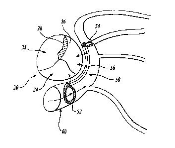
FIGURE 1 illustrates a mitral valve 20 having a number of flaps 22, 24 and 26
that should overlap and close when the ventricle of the heart contracts. As
indicated
above, some hearts may have a mitral valve that fails to close properly
thereby creating
one or more gaps 28 that allow blood to be pumped back into the left atrium
each time the
heart contracts. To add support to the mitral valve such that the valve
completely closes,
an intravascular support 50 is placed in a coronary sinus and vessel 60 that
passes
adjacent one side of the mitral valve 20. The intravascular support 50 has a
proximal
anchor 52, a distal anchor 54, and a support wire 56 or reshaper extending
between the
proximal and distal anchors. With the anchors 52 and 54 in place, the support
wire 56
exerts a force through the coronary sinus wall on the postero-lateral mitral
valve 20
thereby closing the one or more gaps 28 formed between the valve flaps. With
the
intravascular support 50 in place, the function of the mitral valve is
improved.
As will be explained in further detail below, each of the proximal and distal
anchors 52, 54 preferably circumferentially engages the wall of the vessel 60
in which it
-12-
CA 02950492 2016-12-01
is placed. The support wire 56 is secured to a peripheral edge of the proximal
and distal
anchors such that the support wire is urged by the anchors against the vessel
wall.
Therefore, the support wire 56 and anchors 52,54 present a minimal obstruction
to blood
flowing within the vessel.
FIGURE 2 shows one possible method of delivering the intravascular support of
the present invention to a desired location in a patient's body. An incision
80 is made in
the patient's skin to access a blood vessel. A guide catheter 82 is advanced
through the
patient's vasculature until its distal end is positioned adjacent the desired
location of the
intravascular support. After positioning the guide catheter 82, a delivery
catheter and
advancing mechanism 84 are inserted through the guide catheter 82 to deploy
the
intravascular support at the desired location in the patient's body. Further
detail regarding
one suitable advancing mechanism 84 is described in commonly assigned U. S.
Patent
No. 7,316,708 issued January 8, 2008.
FIGURE 3 illustrates one embodiment of an intravascular support in accordance
with the present invention. The intravascular support 100 includes a support
wire 102
having a proximal end 104 and a distal end 106. The support wire 102 is made
of a
biocompatible material such as stainless steel or a shape memory material such
as nitinol
wire.
In one embodiment of the invention, the support wire 102 comprises a double
length of nitinol wire that has both ends positioned within a distal crimp
tube 108. To
form the support wire 102, the wire extends distally from the crimp tube 108
where it is
bent to form a distal stop loop (see 121 in FIGURE 4) having a diameter that
is larger
than the lumens within the distal crimp tube 108. After forming the distal
stop loop, the
wire returns proximally through the crimp tube 108 towards the proximal end of
the
support 100. Proximal to the proximal end of the crimp tube 108, is a distal
lock 110 that
is formed by the support wire bending away from the longitudinal axis of the
support 102
and then being bent parallel to the longitudinal axis of the support before
being bent
again towards the longitudinal axis of the support. Therefore, the bends in
the support
wire form a half 110a of the distal lock that is used to secure the distal
anchor in the
manner described below. From the distal lock 110, the wire continues
proximally
through a proximal crimp tube 112. On exiting the proximal end of the proximal
crimp
tube 112, the wire is bent to form an arrowhead-shaped proximal lock 114. The
wire of
the
-13-
CA 02950492 2016-12-01
support 102 then returns distally through the proximal crimp tube 112 to a
position just
proximal to the proximal end of the distal crimp tube 108 wherein the wire is
bent to form
a second half 110b of the distal lock 110.
Support wire 102 has a length that is selected based on its intended
destination
within a patient's vessel. For use in supporting a mitral valve, the support
wire is
preferably between one and six inches long and has a curved bend between its
proximal
end 104 and distal end 106 with a radius of curvature between 1 and 3 inches
and most
preferably with a radius of curvature of 1.8 inches. In addition, the wire
used to form the
support wire 102 is flexible enough to move with each heartbeat (thereby
changing the
force applied to the mitral valve annulus during the heartbeat) and stiff
enough to support
the mitral valve. In one embodiment, the wire used to form the support wire
102 is made
of nitinol having a modulus of elasticity of 5-20 x 106 psi and a diameter of
between
0.0110" and 0.0150" and most preferably 0.0140". Other shape memory materials
may
be used for support wire as well.
At the distal end of the support wire 102 is a distal anchor 120 that is
formed of a
flexible wire such as nitinol or some other shape memory material. As is best
shown in
FIGURES 3 and 4, the wire forming the distal anchor has one end positioned
within the
distal crimp tube 108. After exiting the distal end of the crimp tube 108, the
wire forms a
figure eight configuration whereby it bends upward and radially outward from
the
longitudinal axis of the crimp tube 108. The wire then bends back proximally
and crosses
the longitudinal axis of the crimp tube 108 to form one leg of the figure
eight. The wire
is then bent to form a double loop eyelet or loop 122 around the longitudinal
axis of the
support wire 102 before extending radially outwards and distally back over the
longitudinal axis of the crimp tube 108 to form the other leg of the figure
eight. Finally,
the wire is bent proximally into the distal end of the crimp tube 108 to
complete the distal
anchor 120.
The distal anchor is expanded by sliding the double eyelet 122 of the distal
anchor
from a position that is proximal to the distal lock 110 on the support wire to
a position
that is distal to the distal lock 110. The bent-out portions 110a and 110b of
support
wire 110 are spaced wider than the width of double eyelet 122 and provide
eamming
surfaces for the locking action. Distal movement of eyelet 122 pushes these
camming
surfaces inward to permit eyelet 122 to pass distally of the lock 110, then
return to their
original spacing to keep eyelet 122 in the locked position.
-14-
CA 02950492 2016-12-01
The dimensions of the distal anchor are selected so that the diameter of the
distal
anchor in a plane perpendicular to the axis of the lumen in which the anchor
is deployed
is preferably between 100% and 300%, most preferably between 130% and 200%, of
the
diameter of the lumen prior to deployment. When treating mitral valve
regurgitation by
placement of the device in the coronary sinus, the diameter of the coronary
sinus may
expand over time after deployment. Oversizing the anchor combined with the
inherent
deformability and recoverability properties of the anchor material
(particularly nitinol or
some other shape memory material) enables the anchor to continue to expand
from its
initial deployment size as the lumen distends and expands over time.
Upon expansion, the distal anchor circumferentially engages the vessel wall
with
a radially outwardly directed force that is distributed unequally around the
circumference
of the anchor by distending the vessel wall in variable amounts along the
axial length of
the anchor. The unequal distribution of force helps the anchor contact the
lumen wall
securely by creating bumps and ridges that are not parallel to the central
axis of the
lumen. In its expanded configuration the distal anchor's diameter is at least
50%-500%
and most preferably 100%-300% of the anchor's diameter in the unexpanded
configuration. The open cross-sectional area of the lumen through the anchor
is at
least 50% and most preferably 80%-100% of the lumen cross sectional area prior
to
redeployment of the anchor.
In addition, the metal coverage of the anchor, as defined by the percentage of
the
lumen surface area through which the anchor extends that is exposed to a metal
surface, is
between 5% and 30% and most preferably 10%. The wire used to form the distal
anchor 120 is preferably nitinol having a diameter of between 0.0110" and
0.0150" and
most preferably 0.0140 inches. Other shape memory materials may be used as
well.
During insertion, a physician can tactilely feel when the eyelet 122 has been
slid
over the distal lock 110 in order to determine when the distal anchor has been
set within a
vessel lumen. In addition, if the anchor is misplaced, it can be collapsed by
pulling the
eyelet 122 proximally over the distal lock 110 and repositioning the anchor in
the
unexpanded configuration. The force required to capture the distal anchor is
preferably
less than 20 lbs. and more preferably less than 10 lbs.
FIGURE 4 also illustrates how the crimp tube 108 is held in place between the
distal lock 110 on the proximal side and the stop loop 121 at the distal end
of the support
wire 102. The wires of the distal anchor 120 exit the distal end of the crimp
tube 108 at
-15-
CA 02950492 2016-12-01
an angle of approximately 45 degrees before looping back over the length of
the distal
crimp tube 108. Therefore, the distal end of the anchor is relatively
atraumatic to avoid
damage to a vessel during placement.
At the proximal end of the intravascular support is a proximal anchor 140 that
is
preferably formed of a biocompatible, elastic wire such as stainless steel or
a shape
memory material such as nitinol. As is best shown in FIGURES 3 and 5, the
proximal
anchor 140 in one embodiment is made of a single length of wire having a first
end
positioned within a proximal crimp tube 112. The wire extends distally from
the crimp
tube 112 and bends radially outward and away from the longitudinal axis of the
crimp
tube 112 before being bent proximally and crossing the longitudinal axis of
the crimp
tube 112 in order to form a first leg of a figure eight configuration. The
wire then is bent
to form a double eyelet or loop 142 around the longitudinal axis of the
support wire 102
wherein the eyelet 142 has a diameter that allows it to be forced over the
proximal
lock 114. After forming the eyelet 142, the wire extends outwardly and away
from the
longitudinal axis of the crimp tube 112 before being bent distally over and
across the
longitudinal axis of the crimp tube 112 to form the second leg of a figure
eight. Finally,
the wire is bent proximally and extends into the distal end of the crimp tube
112.
Like the distal anchor, the proximal anchor is expanded and locked by sliding
the
double eyelet 142 of the proximal anchor from a position that is proximal to
the proximal
lock 114 on the support wire to a position that is distal to the proximal lock
114. As can
be seen in FIGURE 7, the proximal lock 114 has an "arrowhead" shape whereby
the
proximal end of the lock is bent away from the longitudinal axis of the
support wire at an
angle that is less steep than the distal end of the proximal lock. The less
steep section
makes it easier to advance the eyelet 142 over the lock in the distal
direction than to
retrieve the eyelet 142 over the proximal lock 114 in the proximal direction.
Distal
movement of eyelet 142 cams the less steep proximal surfaces inward to permit
eyelet 142 to pass distally of the lock 114, then return to their original
spacing to keep
eyelet 142 in the locked position.
As can be seen by comparing the proximal anchor 140 with the distal anchor 120
in FIGURE 3, the proximal anchor has a larger radius of curvature because it
is designed
to fit within a larger diameter portion of the coronary sinus. The dimensions
of the
proximal anchor are selected so that the diameter of the proximal anchor in a
plane
perpendicular to the axis of the lumen in which the anchor is deployed is
preferably
-16-
CA 02950492 2016-12-01
between 100% and 300%, most preferably between 130% and 200%, of the diameter
of
the lumen prior to deployment. As with the distal anchor, oversizing the
proximal anchor
combined with the inherent deformability and recoverability properties of the
anchor
material (particularly nitinol or some other shape memory material) enables
the anchor to
continue to expand from its initial deployment size as the lumen distends and
expands
over time.
Upon expansion, the proximal anchor circumferentially engages the vessel wall
with a radially outwardly directed an force that is distributed unequally
around the
circumference of the anchor by distending the vessel wall in variable amounts
along the
axial length of the anchor. As with the distal anchor, the unequal
distribution of force
helps the proximal anchor contact the lumen wall securely by creating bumps
and ridges
that are not parallel to the central axis of the lumen. In its expanded
configuration the
proximal anchor's diameter is at least 50%-500% and most preferably 100%-300%
of the
anchor's diameter in the unexpanded configuration. The open cross-sectional
area of the
lumen through the anchor is at least 50% and most preferably 80%400% of the
lumen
cross sectional area prior to redeployment of the anchor.
In one embodiment of the invention, the proximal and distal anchors are
oriented
such that the planes of the anchors are offset with respect to each other by
an angle of
approximately 30 degrees. The offset helps the intravascular support 100 seat
itself in the
coronary sinus and vessel sunounding the mitral valve in certain mammals.
However, it
will be appreciated that if the support is designed for other uses, the
proximal and distal
anchors may be offset by more or less depending upon the anatomy of the
intended
destination.
FIGURES 6A-6C illustrate cross-sectional views of the crimp tubes in which the
wires that form the support wire 102 and proximal and distal anchors 120, 140
are
threaded. In one embodiment, the crimp tubes comprise a biocompatible material
such as
titanium having a number of holes extending longitudinally through the tube
through
which the wires are threaded. In FIGURE 6A, a tube 150 has four holes 152,
154, 156,
158 positioned in approximately a square configuration within the
circumference of the
tube 150. As shown in FIGURE 6B, a tube 160 includes four Holes 162, 164, 166,
168
therein that are positioned in a diamond configuration. FIGURE 6C shows
another
tube 170 having four holes 172, 174, 176, 178. Here the holes 172, 174 lie in
a first plane
and the second pair of holes 176, 178 lie in a second plane that is offset
from the plane of
-17-
CA 02950492 2016-12-01
the holes 172, 174. By changing the orientation of the holes 176, 178 with
respect to the
holes 172, 174, the relative plane of wires passing through the holes can he
adjusted.
Thus in the example shown in FIGURE 3, the proximal anchor may be formed with
a
crimp tube such as that shown in FIGURE 6A or FIGURE 6B while the proximal
anchor
may be formed in a crimp tube such as that shown in FIGURE 6C in order to
adjust the
angular orientation between the proximal anchor and the distal anchor. In an
alternative
embodiment, the crimp tubes at the proximal and distal ends of the support
wire 102 are
the same and the angular offset between the proximal and distal anchor is
achieved by
bending the wires at the desired angle. Although the crimp tubes shown use one
hole for
each wire passing through the crimp tube, it will be appreciated that other
configurations
may be provided such as slots or other passages for the wires to pass through.
In another embodiment, the distal and proximal anchors are attached to the
support wire by a wire, such as nitinol wire or other shape memory material.
The
attaching wire may be spiral wrapped around the base of each anchor and around
the
support wire. In another embodiment, each anchor may be attached to the
support wire
by wrapping the anchor wire around the support wire. In yet another
embodiment, the
two anchors and the support wire may be made from a single wire, such as
nitinol wire or
other shape memory material.
FIGURE 8 illustrates one method for delivering an intravascular support 100 in
accordance with the present invention to a desired location in The body. As
indicated
above, intravascular support 100 is preferably loaded into and routed to a
desired location
within a catheter 200 with the proximal and distal anchors in a collapsed or
deformed
condition. That is, the eyelet 122 of the distal anchor 120 is positioned
proximally of the
distal lock 110 and the eyelet 142 of the proximal anchor 140 is positioned
proximal to
the proximal lock 114. The physician ejects the distal end of the
intravascular support
from the catheter 200 into the lumen by advancing the intravascular support or
retracting
the catheter or a combination thereof. A pusher (not shown) provides distal
movement of
the intravascular support with respect to catheter 200, and a tether 201
provides proximal
movement of the intravascular support with respect to catheter 200. Because of
the
inherent recoverability of the material from which it is formed, the distal
anchor begins to
expand as soon as it is outside the catheter. Once the intravascular support
is properly
positioned, the eyelet 122 of the distal anchor is pushed distally over the
distal lock 110
so that the distal anchor 120 further expands and locks in place to securely
engage the
-18-
CA 02950492 2016-12-01
lumen wall and remains in the expanded condition. Next, the proximal end of
the support
wire 102 is tensioned by applying a proximally-directed force on the support
wire and
distal anchor to apply sufficient pressure on the tissue adjacent the support
wire to
modify the shape of that tissue. In the case of the mitral valve, fluoroscopy,
ultrasound or
other imaging technology may be used to see when the support wire supplies
sufficient
pressure on the mitral valve to aid in its complete closure with each
ventricular
contraction without otherwise adversely affecting the patient. A preferred
method of
assessing efficacy and safety during a mitral valve procedure is disclosed in
copending
U. S. Published Application No. 20040158321, filed February 12,2003, and
titled
"Method of Implanting a Mitral Valve Therapy Device. Once the proper pressure
of the
support wire has been determined, the proximal anchor is deployed from the
catheter and
allowed to begin its expansion. The eyelet 142 of the proximal anchor 140 is
advanced
distally over the proximal lock 114 to expand and lock the proximal anchor,
thereby
securely engaging the lumen wall and maintaining the pressure of the support
wire
against the lumen wall.
Finally, the mechanism for securing the proximal end of the intravascular
support
can be released. In one embodiment, the securement is made with a braided loop
202 at
the end of tether 201 and a hitch pin 204. The hitch pin 204 is withdrawn
thereby
releasing the loop 202 so it can be pulled through the proximal lock 114 at
the proximal
end of the intravascular support 100.
In many contexts, it is important for the device to occupy as little of the
lumen as
possible. For example, when using the device and method of this invention to
treat mitral
valve regurgitation, the device should be as open as possible to blood flow in
the
coronary sinus (and to the introduction of other medical devices, such as
pacing leads)
while still providing the support necessary to reshape the mitral valve
annulus through
the coronary sinus wall. The combination of the device's open design and the
use of
nitinol or some other shape memory material enables the invention to meet
these goals.
When deployed in the coronary sinus or other lumen, the device preferably
occupies
between about 1.5% and about 5.5% of the overall volume of the section of
lumen in
which it is deployed.
In many embodiments of the invention, the use of a shape memory material such
as nitinol is particularly important. The percentage of shape memory material
by volume
-19-
CA 02950492 2016-12-01
in the device is preferably between about 30% and 100%, most preferably
between
about 40% and 60%.
In some instances it may be necessary to move or remove an intravascular
support
after deployment by recapturing the device into a catheter. Prior to
deployment of the
proximal anchor, the distal anchor may be recaptured into the delivery
catheter by
simultaneously holding the device in place with tether 201 while advancing
catheter
distally over distal anchor 120 so that the entire device is once again inside
catheter 200.
The distally directed force of the catheter collapses distal anchor 120 into a
size small
enough to fit into catheter 200 again. Likewise, after deployment of both
anchors but
prior to releasing the securement mechanism as described above, the
intravascular
support may be recaptured into the delivery catheter by simultaneously holding
the device
in place with tether 201 while advancing catheter distally first over proximal
anchor 140,
over support wire 102, and finally over distal anchor 120. The distally
directed forced of
catheter 200 collapses anchors 120 and 140 into a size small enough to fit
into
catheter 200 again. If the securement mechanism has been detached from the
device
prior to recapture, the device still may be recaptured into the delivery
catheter or another
catheter by grasping the proximal end of the device with a grasper or tether
and by
advancing the catheter distally over the device.
In one embodiment of the invention, proximal anchor 140 includes a recapture
guidance and compression element. In the embodiment shown in FIGURE 5, the
slope of
the two proximal arms 143 and 144 of proximal anchor 140 is small in proximal
portions 145 and 146 of the arms, then increases in more distal portions 147
and 148 of
the arms. This shape guides the catheter to move distally over the anchor more
easily and
to help compress the anchor to a collapsed shape as the catheter advances
during
recapture.
Likewise, the two proximal arms 123 and 124 of distal anchor 120 have a
shallower slope in their proximal portions 145 and 146 and an increased slope
in more
distal portions 147 and 148. While recapture of the distal anchor is somewhat
easier due
to its smaller size compared to the proximal anchor, this recapture guidance
and
compression feature enhances the ease with which recapture is performed.
FIGURE 9 illustrates an alternative embodiment of the intravascular support of
the present invention. In this embodiment, an intravascular support 250 has a
support
wire 252 and a distal anchor 254 and a proximal anchor 256. In the embodiment
shown
-20-
CA 02950492 2016-12-01
in FIGURE 9, the distal anchor 254 is made from the same wire used to form the
support
wire 252. As best shown in FIGURE 10, the wire used to form the support wire
252
extends distally through a distal crimp tube 260 before looping radially
outward and
returning proximally and across the longitudinal axis of the crimp tube 260 to
form one
leg of a figure eight. The wire then winds around the axis of the suspension
wire 252 to
faun an eyelet 262. The wire then continues radially outward and distally
across the
longitudinal axis of the crimp tube 260 to form the second leg of a figure
eight. After
forming the figure eight, the wire enters the distal end of the crimp tube 260
in the
proximal direction to form the other half of the support wire 252. A distal
lock 264 is
.. formed proximal to the distal crimp tube 260 by outwardly extending bends
in the wires
that form the support wire 252. The distal lock 264 prevents the double eyelet
262 from
sliding proximally and collapsing the distal anchor 254 when positioned in a
vessel.
As shown in FIGURE 11, a distal anchor 256 is constructed in a fashion similar
to
the proximal anchor 140 shown in FIGURE 3. That is, the proximal anchor 256 is
.. formed of a separate wire than the wire used to form the support wire 252
and distal
anchor 254. The wire of the proximal anchor has one end within a proximal
crimp
tube 270. The wire extends distally out of the end of the crimp tube and bends
radially
outward before returning back and across the longitudinal axis of the crimp
tube 270. At
the proximal end of the crimp tube 270, the wire of the proximal anchor forms
a double
.. eyelet 272 around the longitudinal axis of the support wire 252. The wire
then continues
radially outward and distally over the longitudinal axis of the crimp tube 270
to form the
second leg of the figure eight whereupon it is bent proximally into the distal
end of the
crimp tube 270.
FIGURE 12 shows yet another embodiment of an intravascular support in
.. accordance with the present invention. Here, an intravascular support 300
comprises a
support wire 302, a distal anchor 304 and a proximal anchor 306. As in the
embodiment
shown in FIGURE 9, the distal anchor 304 and the support wire 302 are formed
of the
same wire. To form the distal anchor, the wire extends distally through a
distal crimp
tube 310 and exits out the distal end before extending radially outward and
bending back
and across the longitudinal axis of the crimp tube 310 to form one leg of a
figure eight.
The loop then forms an eyelet 312 around the longitudinal axis of the support
wire 302
before bending radially outward and distally across the longitudinal axis of
the crimp
tube 310 to form a second leg of the figure eight. The wire then enters the
distal end of
-21-
CA 02950492 2016-12-01
the crimp tube 310 in the proximal direction. The support wire 302 may have
one or two
outwardly extending sections that form a distal stop 314 to maintain the
position of the
eyelet 312 once the distal anchor is set in the expanded configuration.
The proximal anchor 306 is formed from a separate wire as shown in FIGURE 14.
The wire has one end positioned within the proximal crimp tube 320 that
extends distally
outward and radially away from the longitudinal axis of the crimp tube 320
before being
bent proximally and across the longitudinal axis of the crimp tube 320 to form
one leg of
the figure eight. The wire then winds around the longitudinal axis of the
support wire to
form an eyelet 322 before being bent distally and across the longitudinal axis
of the crimp
tube 320 to enter the distal end of the crimp tube 320 in the proximal
direction. As will
be appreciated, the proximal crimp tube 320 of the embodiment shown in FIGURE
12
holds four wires wherein the distal crimp tube 310 need only hold two wires.
FIGURES 15-18 show other embodiments of the invention. In the embodiment
shown in FIGURE 15, the intravascular support has an anchor 400 formed as a
loop 404
emerging from a window 406 in a crimp tube 408. Extending from one end 411 of
crimp
tube 408 is a support strut 410 which connects with loop 404. Also extending
from the
crimp tube 408 is a support wire 412. Loop 404 and support 410 may be formed
from
nitinol, stainless steel, or any other appropriate material. The intravascular
support
includes another anchor. The intravascular support of this embodiment may be
delivered
.. and deployed in the manner discussed above with respect to the embodiment
described
above.
FIGURE 16 shows another embodiment of an anchor 450 for an intravascular
support. Anchor 450 is formed from two loops 452 and 454 emerging from a
window 456 and an end 457 of a crimp tube 458. A support wire 462 also extends
from
.. the crimp tube. Loops 452 and 454 may be formed from nitinol, stainless
steel, or any
other appropriate material. The intravascular support includes another anchor.
The
intravascular support of this embodiment may be delivered and deployed in the
manner
discussed above with respect to the embodiment described above.
FIGURE 17 shows yet another embodiment of an anchor 500 for an intravascular
support according to this invention. Anchor 500 is formed from two loops 502
and 504
emerging from a window 506 and an end 507 of a crimp tube 508. A cross strut
505
connects the loops. A support wire 512 also extends from the crimp tube. Loops
502
and 504 and strut 505 may be formed from nitinol, stainless steel, or any
other
-22-
CA 02950492 2016-12-01
appropriate material. The intravascular support includes another anchor.
The
intravascular support of this embodiment may be delivered and deployed in the
manner
discussed above with respect to the embodiment described above.
FIGURE 18 is a modification of the embodiment shown in FIGURES 3-7. In this
embodiment, torsional springs 558 of proximal anchor 550 have been formed as
single
loops or eyelets in the anchor's wire 552. These springs make the anchor 550
more
compliant by absorbing some of the force applied to the anchor during locking.
While
FIGURE 18 shows a proximal anchor with two springs 558, any number of springs
could
be used on either the proximal or the distal anchor.
Referring now to FIGURE 19, it is a superior view of a human heart 610 with
the
atria removed to expose the mitral valve 612, the coronary sinus 614, the
coronary
artery 615, and the circumflex artery 617 of the heart 610 to lend a better
understanding
of the present invention. Also generally shown in FIGURE 19 are the pulmonary
valve 622, the aortic valve 624, and the tricuspid valve 626 of the heart 610.
The mitral valve 612 includes an anterior cusp 616, a posterior cusp 618 and
an
annulus 620. The annulus encircles the cusps 616 and 618 and maintains their
spacing to
provide a complete closure during a left ventricular contraction. As is well
known, the
coronary sinus 614 partially encircles the mitral valve 612 adjacent to the
mitral valve
annulus 620. As is also known, the coronary sinus is part of the venous system
of the
heart and extends along the AV groove between the left atrium and the left
ventricle.
This places the coronary sinus essentially within the same plane as the mitral
valve
annulus making the coronary sinus available for placement of the mitral valve
therapy
device of the present invention therein.
FIGURE 20 shows a mitral valve therapy device 630 embodying the present
invention shown deployed in the coronary sinus 614 of the heart 610 adjacent
the mitral
valve annulus 620 for effecting the geometry of the mitral valve annulus. Also
shown in
FIGURE 20 is a deployment system 650 that deploys the device 630 in the
coronary
sinus 614. The device 630 takes the form of an elongated body 632 which
includes a
distal anchor 634 embodying the present invention and a proximal anchor 636.
The anchors 634 and 636 are shown in FIGURE 20 in their deployed
configuration. As will be seen hereinafter, upon deployment of the device 630
in the
coronary sinus, the distal anchor 634 is transitioned from a first
configuration to a locked
second configuration. In the process, it is expanded outwardly to anchor the
device in the
-23-
CA 02950492 2016-12-01
coronary sinus against both bi-directional longitudinal and rotational
movement. The
proximal anchor however, when deployed, is configured to permit proximal
movement.
This allows the device 630 to be tightened within the coronary sinus by
proximal pulling
of the anchor 636 after the distal anchor 634 is deployed. The device 630 may
be formed
from Nitinol or stainless steel, for example.
The deployment system 650 illustrated in FIGURE 20 includes an elongated
catheter 652, an elongated pusher 654, and a tether 656. In deploying the
device 630, the
tether 656 is first looped about the proximal anchor 636 of the device 630 as
illustrated
and the device is then loaded into the catheter 650. The tether 656 is then
threaded
through an internal lumen 658 of the pusher 654 and looped around the proximal
anchor 636 of the device 630 as illustrated. The pusher 654 is then advanced
along the
tether 656 for engaging the device 630 and pushing the device distally down
the catheter
to a predetermined position at the distal end of the catheter 650. The
catheter with the
device 630 loaded therein is then fed into the heart and through the coronary
sinus
ostium 630 into the coronary sinus to place the catheter in a position such
that the
device 630 is adjacent the mitral valve annulus 620. Thereafter, the device is
maintained
in a stationary position by the pusher 654 as the catheter 650 is partially
withdrawn to
expose the distal anchor 634. Once the distal anchor is exposed, it is
deployed by the
catheter in a manner to be described more particularly with respect to FIGURES
21-24.
Once the distal anchor 634 is deployed, the catheter 650 is then retracted
proximally of
the proximal anchor 636. This exposes the proximal anchor 636 and permits the
proximal anchor to self deploy. Once the proximal anchor is deployed, the
tether 656 is
pulled proximally to move the proximal anchor 636 in a proximal direction for
tightening
the device within the coronary sinus and to an extent which results in the
desired effect on
.. the geometry of the mitral valve annulus 620. During this adjustment
process, mitral
regurgitation may be monitored and the device adjusted for optimal results.
When the
device 630 is in its final position within the coronary sinus 614, the pusher
654 and
catheter 650 may be removed from the heart. The tether 656 may be permitted to
remain
in the heart during an acute phase to ascertain the effectiveness of the
device 630. Should
.. further adjustment of the device he necessary, the tether 656 may then be
used as a guide
for guiding the introduction of the catheter 650 back into the heart.
FIGURES 21-24 illustrate the manner in which the distal anchor 634 may be
deployed in the coronary sinus 614 for anchoring the device 630. It will be
appreciated
-24-
CA 02950492 2016-12-01
by those skilled in the art, of course, that the anchor 634 may be utilized in
body lumens
other than the coronary sinus and with therapeutic devices other than the
mitral valve
annulus therapy device illustrated in FIGURE 20.
In each of FIGURES 21-24 a portion of the coronary sinus has been removed and
the pusher has not been illustrated so as to not unduly complicate the
figures.
FIGURE 21 shows the catheter 650 disposed within the coronary sinus 614 with
the
device 630 and distal anchor within the catheter 650. To that end, the
catheter includes a
lumen 660 which is dimensioned to receive the device 630 and the distal anchor
634
when the distal anchor 634 is in a first configuration. The distal anchor 634
includes an
elongated fixation member 638 which is hingedly coupled to the distal end of
the
device 630 at a hinge 640. The elongated fixation member thus extends along
the body
of the device 630. The fixation member includes a support 642 which is an
extension of
the fixation member 638 and which is hingedly connected to the fixation member
638 at a
hinge point 644. The proximal end of the fixation member 638 includes a loop
646
which is looped about the device 630 to permit the loop 646 to slide along the
device 630.
As will be seen subsequently, the loop 646 forms part of a lock for locking
the
anchor 634 in a second configuration for anchoring in the coronary sinus.
To complete the anchor, the device 630 includes a resilient enlarged portion
648
over which the loop 646 may slide. Once the loop 646 is located distally of
the enlarged
portion 648, it will be held by the enlarged portion 648 for locking the
device in the
second configuration.
FIGURE 22 illustrates the anchor 634 after the catheter 650 has been moved
proximal to the anchor 634. More specifically, it will be noted that the
distal end of the
catheter 650 is now proximal to the loop 646 or proximal end of the anchor
634. The
shape memory of the anchor has caused the anchor to expand and is now
partially
transitioned from the first configuration of FIGURE 21 to the second and final
configuration to be described with reference to FIGURE 24 subsequently.
FIGURE 23 illustrates the anchor 634 being *transitioned from the first
configuration to the second configuration. This transition is implemented by
the distal
end of the catheter 650 pushing the proximal end of the anchor 634 in the
distal direction.
To maintain the position of the anchor 634 during the transition, the tether
656 is used to
hold the device 630 against distal movement.
-25-
CA 02950492 2016-12-01
The particular configuration of the distal anchor 634 in accordance with this
embodiment may be more particularly seen in FIGURE 23. Here it may be seen
that the
distal anchor is formed of a wire having a first end secured to the distal end
of the
device 630, folded back and looped around the device and then back to the
distal end of
the device. Both ends of the anchor are then crimped by a crimp 670. This
configuration
results in a pair of fixation members 638 each having a support extension 642.
In
addition, the fixation members 638 may be formed so as to have a loop
configuration to
maximize surface contact with the inner wall of the coronary sinus 614.
As the catheter 650 is moved distally, it forces the loop 646 of the anchor
634
over the enlarged portion 648 of the device 630 to a point distal to the
enlarged
portion 648. This locks the loop 646 distally of the enlarged portion 648 for
locking the
anchor 634 in an enlarged second configuration as illustrated in FIGURE 24 to
anchor the
device 630 within the coronary sinus 614. More specifically, it may be seen
that the
supports 642 have been pivoted at the hinge 644 relative to the fixation
member 638.
This allows the fixation members 638 to be supported by the supports 642 and
securely
locked by the lock of the loop 646 and enlarged portion 648 of the device 630.
The
fixation members 638 provide broad surface contact with the inner wall of the
coronary
sinus 614. This provides for anchoring within the coronary sinus of the device
630
against both bi-directional longitudinal and rotational movement. Once the
anchor 634 is
deployed as illustrated in FIGURE 24, the catheter 650 may then be removed as
indicated
by the arrow 672.
One of the many features of the anchor of the instant invention is that it may
be
moved within or removed from the body lumen in which it is deployed. More
specifically, and making reference to FIGURE 24, the anchor 634 may be removed
by
grabbing the support members 642 and pulling the loop 646 over the resilient
enlarged
portion 648 of the device 630. When the loop 646 is on the proximal side of
the enlarged
portion 648, further proximal movement of the loop 646 will fully transition
the
anchor 634 from the second configuration back to the first configuration for
removal
within the catheter 650.
Alternatively, by virtue of the support members, the anchor 634 may be formed
of
deformable material such as stainless steel. Using this to advantage, the
anchor 634 may
be partially collapsed by the catheter 650 to permit the anchor 634 and hence
the
device 630 to be moved and repositioned in the coronary sinus after which the
resilience
-26-
CA 02950492 2016-12-01
of the anchor material returns the anchor to its locked and deployed
configuration. The
anchor may be collapsed by the catheter 650 as illustrated in FIGURES 25 and
26.
In FIGURE 25, it will be noted that the catheter 650, while the device is held
stationary by the tether, is moved distally over the enlarged portion 648 and
the loop 646.
The anchor 634 is now partially collapsed for movement and repositioning. Once
repositioned, the catheter may be withdrawn to redeploy the anchor 634 which
returns to
its second configuration by virtue of its resiliency and shape memory.
As seen in FIGURE 26, continued distal movement of the catheter 650 causes the
anchor 634 to fidly collapse. This allows the anchor 634 to be totally drawn
into the
catheter 650. Once the anchor 634 is collapsed and within the catheter 650,
the
device 630 may be removed by removing the catheter with the device therein or
by
pulling the device proximally through the catheter.
FIGURES 27-30 illustrate alternative embodiments of the anchor of the present
invention. These embodiments are once again illustrated in connection with the
anchoring of a mitral valve annulus therapy device within the coronary sinus
of a heart.
In FIGURE 27, the device 630 is shown having a plurality of enlarged
portions 646. As a result, a plurality of locks are provided on the device 630
to enable the
fixation members to be locked at any one of a plurality of intermediate points
between the
first configuration and a maximum second configuration illustrated in FIGURE
27. This
enables the anchor 634 to be sized to a given body lumen.
FIGURE 28 shows another anchor 684 embodying the present invention which
has a separate fixation member 688 and support member 692. The second or
distal end of
the fixation member 688 is hingedly coupled to a first or distal end of the
support
member 692 by a hinged connection 694. The fixation member 688 may have a hoop
configuration as the fixation members 638 previously described.
FIGURES 29 and 30 illustrated a still further anchor 704 having a pair of
fixation
members 708 and corresponding separate support members 712. Here, the fixation
members 708 are formed by immediately adjacent anchor wires which, as best
seen in
FIGURE 30, are disposed at an angle to permit a cardiac lead, indicated by the
dashed
circle 720, to pass through the anchor and thus be within the coronary sinus.
Hence, a
device having an anchor such as anchor 704 is compatible with the provision of
a cardiac
lead therewith.
-27-
CA 02950492 2016-12-01
As can thus been seen, the present invention provides a new and improved
anchor
for anchoring a therapeutic device within a body lumen. The anchor of the
present
invention, by virtue of the lockable support member, creates mechanical
advantage to
assist deployment of the anchor. This also increases anchor strength. Because
the
support members may be of hooped or looped configuration, increased contact
area
between the anchor and the body lumen can be achieved. In addition, the anchor
of the
present invention allows deactivation and repositioning of the anchor or
therapeutic
device incorporating the anchor. Still further, because of the locked support
structure, the
anchor may be formed of smaller diameter wire, tube wall, or other materials
which
without the locked support provided by the anchor of the present invention
would be
unsuitable for this application.
Referring now to FIGURE 31, it is a superior view of a human heart 810 with
the
atria removed to expose the mitral valve 812, and the coronary sinus 814 of
the heart 810.
Also generally shown in FIGURE 31 are the pulmonary valve 822, the aortic
valve 824,
and the tricuspid valve 826 of the heart 810.
The mitral valve 812 includes an anterior cusp 816, a posterior cusp 818 and
an
annulus 820. The annulus encircles the cusps 816 and 818 and maintains their
spacing to
provide a complete closure during a left ventricular contraction. As is well
known, the
coronary sinus 814 partially encircles the mitral valve 812 adjacent to the
mitral valve
annulus 820. As is also known, the coronary sinus is part of the venus system
of the heart
and extends along the AV groove between the left atrium and the left
ventricle. This
places the coronary sinus essentially within the same plane as the mitral
valve annulus
making the coronary sinus available for placement of the mitral valve therapy
device of
the present invention therein.
FIGURE 32 shows a mitral valve therapy device 830 embodying the present
invention shown deployed in the coronary sinus 814 of the heart 810 adjacent
the mitral
valve annulus 820 for effecting the geometry of the mitral valve annulus. The
device 830
takes the form of an elongated body 832 which includes a distal anchor 834 and
a
proximal anchor 836.
The anchors 834 and 836 are shown in FIGURE 32 in their deployed
configuration. In deploying the device 830 in the coronary sinus, the distal
anchor 834 is
first deployed to anchor the distal end of the device 830. In the anchoring
process, the
anchor 834 is expanded outwardly to anchor the device in the coronary sinus
against both
-28-
CA 02950492 2016-12-01
bi-directional longitudinal and rotational movement. This allows the device
830 to be
tightened within the coronary sinus by pulling of the device's proximal end.
Then, the
proximal anchor 836 is deployed. The device 830, which may be formed from
Nitinol or
stainless steel, for example, now exerts an inward pressure on the mitral
valve annulus 820
to advantageously effect its geometry.
The device 830 along with its deployment system 850 is illustrated in FIGURE
33.
As shown, the device is in the process of being implanted in the coronary
sinus 814 of the
heart 810. Its proximal anchor 836 and distal anchor 834 have yet been
deployed. The
deployment system 850 includes an elongated catheter 852, an elongated pusher
854, a
coupling structural member 856 and a locking pin 858. As may be noted in
FIGURE 34,
the proximal end of the device 830 includes a coupling loop 838. The pusher
854 is
preferably an elongated coil having a center lumen 855. The coupling member
856 is
formed from a cable that is provided with a loop 857. The legs or ends 859 of
the loop 857
extend proximally through the lumen 855 and out the proximal end of the pusher
854.
The locking pin 858 also extends proximally out of the proximal end of the
pusher
854. As shown in FIGURE 34, the coupling loops 838 and 857 are aligned to
overlap and
the locking pin 858 is extended through the overlapping loops. This causes the
device 830
to be releasably locked to the pusher 854.
In deploying the device 830, the catheter 852 is first fed into the coronary
sinus
814 adjacent the mitral valve annulus 820. The device 830 and pusher 854 are
then
releasably locked together as shown in FIGURE 34. The device is then loaded
into the
catheter 852. The pusher 854 follows the device into the catheter 852 and is
then advanced
along the catheter to push the device 830 distally down the catheter to a
predetermined
position adjacent the mitral valve annulus 814 at the distal end of the
catheter 852.
Thereafter, the device is maintained in a stationary position by the pusher
854 as the
catheter 852 is partially withdrawn to expose the distal anchor 834.
Once the distal anchor 834 is exposed, it is deployed in a manner as fully
described
in commonly assigned US Patent No. 6,824,562 issued November 30, 2004. Once
the
distal anchor 834 is deployed, the catheter 850 is then retracted proximally
of the proximal
anchor 836. This exposes the proximal anchor 836. Once the proximal anchor is
exposed,
the pusher 854 is pulled proximally for tightening the device within the
coronary sinus and
to an extent which results in the desired effect on the geometry of the
-29-
CA 02950492 2016-12-01
mitral valve annulus 820. During this adjustment process, mitral regurgitation
may be
monitored and the device adjusted for optimal results. When the device 830 is
in its final
position within the coronary sinus 814, the proximal anchor 836 may then be
deployed.
The beneficial effect of the device may now again be evaluated. Once the
device is ready
for chronic implant, the locking pin 858 may be pulled proximally from the
proximal end
of the pusher 854 as shown in FIGURE 35 to disengage the coupling members 838
and 856. With the pusher 854 now free from the device 830, the pusher 854,
catheter 852, coupling member 856 and locking pin 858 may then be removed from
the
heart.
As can be appreciated by those skilled in the art, guide members, other than a
guide catheter as shown herein, may be used to direct the device into the
coronary sinus.
For example, a guide wire, of the type well known in the art may alternatively
be
employed to guide the device there along into the coronary sinus without
departing from
the present invention.
FIGURES 36 and 37 illustrate the manner in which the device 830 may be
removed from the coronary sinus 814 if necessary in accordance with further
aspects of
the present invention. As may be seen in FIGURES 36 and 37, the device 830 may
be
removed from the coronary sinus 814 with a retractor assembly 860. The
retractor
assembly includes the catheter 862, and a retractor 864 comprising an
elongated coil 865
and a coupling member 866. The elongated coil 865 of the retractor 864 is
essentially
identical to the pusher 854 as illustrated in FIGURES 33-35. The coupling
member 866
may be a cable which extends down the center lumen of the elongated coil 865
to form a
loop structure 866 and which then returns through the center lumen of the
elongated
coil 865 such that the free ends 869 of the cable 863 extend out the proximal
end of the
elongated coil 865. As also seen in FIGURES 36 and 37, if the device 830 is to
be
removed from the coronary sinus 814, the cable 863 is threaded into the
elongated
coil 865 to form the loop structure 866. With the retractor 864 thus formed,
the retractor
is then guided down the catheter 862 to the proximal end of the device 830 and
more
specifically to the coupling loop member 838 of the device 830. The loop 866
of the
cable 863 is then wrapped about the loop coupling member 838 of the device 830
and the
free ends 869 of the cable are drawn proximally to tighten the loop structure
866 about
the loop coupling member 838. The retractor 864 now has a grip on the device
830.
With the device 830 now being firmly held by the retractor 864, the retractor
864 may be
-30-
CA 02950492 2016-12-01
pulled proximally within the catheter 862 to impart proximal movement to the
device 830.
When the anchors 834 and 836 of the device 830 engage the distal end of the
catheter 862,
they will be collapsed to disengage from the coronary sinus. The device may
now be
removed by pulling on the retractor 864 proximally within the catheter 862
until the
device is fully removed from the heart and the patient. Alternatively, the
device may be
drawn into the catheter. The catheter and the device may then be withdrawn
together from
the patient.
FIGURES 38-40 illustrate a further embodiment of the present invention for
releasably locking a pusher member to a mitral valve therapy device for
implanting the
mitral valve therapy device adjacent the mitral valve annulus within the
coronary sinus of
the heart.
As illustrated in FIGURE 38, the mitral valve therapy device 870 is elongated
and
includes a distal anchor 874 and a proximal anchor 876. The anchors are not
yet deployed.
The device 870 further includes, at its proximal end, a coupling structure
878.
For deploying the device 870, a deployment system 890 is also illustrated. The
deployment system includes a catheter 892, a pusher member 894, a coupling
structure
896 at the distal end of the pusher 894, and a locking member 898. As will be
best seen in
FIGURE 39, the coupling member 878 of the device 870 and the coupling member
896 of
the pusher 894 form a pair of interlocking structures. The coupling structures
878 and 896
are tubular and the locking member 898 is also tubular.
When it is desired to implant the device 870, the device 870 is coupled to the
pusher 898 by the interlocking structures of the coupling members 878 and 896
which are
held together and in place by the locking member 898. Then, as previously
described in
the previous embodiment, the device and pusher member are fed down the
catheter 892
until the device reaches a desired position within the coronary sinus adjacent
the mitral
valve annulus 820. Once in this position, the device is held stationary by the
pusher
member 894 while the catheter 892 is retracted to expose the distal anchor
874. The distal
anchor 874 may now be deployed in a manner as described in the aforementioned
commonly assigned US Patent No. 6,824,562. With the distal anchor 874
deployed, the
catheter 892 is then retracted until it is proximal to the proximal anchor
876. The pusher
894 may then be pulled to tighten the device within the coronary sinus. Once
the device
870 has been tightened to a desired degree, as confirmed by device
effectiveness
evaluation, the device 870 is ready for chronic implant.
-31-
CA 02950492 2016-12-01
When the device 870 is to be left within the coronary sinus 814, the tether
899 is
pulled to slide the locking member 898 off of the interlocking structures 878
and 896.
The coupling structures of the pusher 894 may be prestressed for disengaging
the
coupling structure 878 of the device 870 when the locking member 898 is pulled
proximal to the interlocking structures. The device 870 is now free from the
pusher
member 894. The pusher member 894 together with the tether, locking member,
and
catheter 892 may be removed from the heart. With the implant of the device 870
completed, the device 870 is left within the coronary sinus adjacent the
mitral valve
annulus 820 to treat the mitral valve such as by eliminating mitral
regurgitation.
As illustrated in FIGURE 40, the coupling structure 896 is prestressed to
deflect
outwardly when the tubular locking member 898 is pulled proximally to
disengage the
device 870 from the pusher 894. Alternatively, the coupling structure 896 may
be
prestressed inwardly with a locking pin (not shown) extending into coupling
stricture 878
to maintain the locked arrangement. Here, proximal pulling of the pin would
cause the
coupling structure 896 to deflect inwardly to disengage the coupling structure
878
and 896.
While the preferred embodiment of the invention has been illustrated and
described, it will be appreciated that various changes can be made therein
without
departing from the scope of the invention. Therefore, the scope of the
invention is to be
determined from the following claims and equivalents thereto.
-32-