Note: Descriptions are shown in the official language in which they were submitted.
METHOD AND SYSTEM FOR IDENTIFYING AND SAMPLING HYDROCARBONS
WITH BUOYS
FIELD OF THE INVENTION
[0002]
This invention relates generally to the field of hydrocarbon exploration and
development. Specifically, the invention relates to operations for exploring
and developing
hydrocarbons (e.g., oil and/or gas) with one or more remote devices, such as
buoys.
BACKGROUND OF THE INVENTION
[0003] Hydrocarbon reserves are becoming increasingly difficult to locate and
access, as
the demand for energy grows globally. As a result, various technologies are
utilized to
collect measurement data and then to model the location of potential
hydrocarbon
accumulations. The modeling may include factors, such as (1) the generation
and expulsion
of liquid and/or gaseous hydrocarbons from a source rock, (2) migration of
hydrocarbons to
an accumulation in a reservoir rock or to the surface, (3) a trap and a seal
to prevent
significant leakage of hydrocarbons from the reservoir. The collection of
data, such as
marine surveying approaches, may be beneficial in modeling potential location
for subsurface
hydrocarbon accumulations.
[0004] One conventional marine surveying approach involves remote sensing an
area of
interest. For example, reflection seismic is the dominant remote sensing
technology for the
identification of hydrocarbon accumulations.
This approach has been successful in
identifying structures that may host hydrocarbon accumulations, and may also
be utilized to
image the hydrocarbon fluids within subsurface accumulations as direct
hydrocarbon
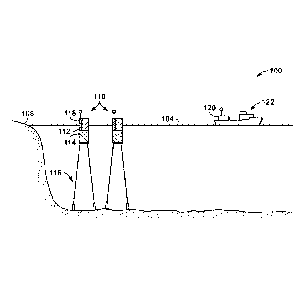
indicators (DHIs). However, this approach may lack the required fidelity to
provide accurate
assessments of the presence and volume of subsurface hydrocarbon accumulations
due to
poor imaging of the subsurface, particularly with increasing depth where
acoustic impedance
1
CA 2951281 2018-04-30
CA 02951281 2016-12-05
WO 2016/011388 PCT/US2015/040965
contrasts that cause DHIs are greatly diminished or absent. Further, non-
seismic hydrocarbon
detection technologies, such as potential field methods like gravity or
magnetics or the like,
provide coarse geologic subsurface controls by sensing different physical
properties of rocks,
but lack the fidelity to identify hydrocarbon accumulations. As such, the
conventional
approaches may merely provide guidance on where a basin seismic survey should
be
conducted, but do not significantly improve the ability to confirm the
presence of
hydrocarbon seeps or subsurface hydrocarbon accumulations.
[0005] Other conventional marine surveying may involve the use of manned
vessels or
vehicles to collect samples. See, e.g., American Standards and Testing
Association's
Standard Practice D4489. However, such sampling approaches are expensive due
to the
vessel deployment requirements and the number of samples is limited by the
amount of time
a vessel and its crew can remain on the body of water to perform operations.
Further,
samples obtained from the manned vessel's operations may fail to obtain
samples from a
target of interest or include samples that are compromised due to marine
vessel traffic or
other disturbances. As a result, the conventional approaches may provide a
limited coverage
area, may require certain amounts of lead time to prepare and deploy the
vessel and crew,
may involve additional verification steps to confirm a target of interest is
present because of
the delays in deployment, and may provide limited flexibility for adjusting a
course plan or
trajectory during operations (e.g., real-time or concurrent adjustments). As
such, manned
marine surveying approaches have various limitations for surveying operations.
[0006] Yet another approach for marine surveying may include remote sensing
coupled
with a sampling operations. This approach may be used to identify possible
features of
interest (e.g., oil slicks from seeps, red tide or a chemical pollutant) or
wildlife (e.g., invasive,
rare, threatened or endangered species locations). The remote sensing may be
performed
indirectly (e.g., with satellite or airborne imaging) or directly (e.g., via
observations and
sampling from a marine vessel). Then, a marine vessel can be deployed with a
manned crew
to determine the location of the observation and to obtain samples. However,
similar to the
discussion above regarding manned approaches, the deployment of a marine
vessel may be
time consuming and expensive to operate. Further, because the deployment
involves
processing remote sensing data and the deployment may involve delays, this
approach may
not be able to locate the ephemeral feature, as it is not performed in a
timely manner. That is,
the target or feature may have aged, dissipated, or moved to a different
location as a result of
changes in conditions, such as currents and/or wind. In addition, a chemical
associated with
2
CA 02951281 2016-12-05
WO 2016/011388 PCT/US2015/040965
the target may have to involve high concentrations to be detected and may have
to be at the
surface to be discernable via satellite or aircraft. Also, this approach may
have difficulties in
addressing and overcoming limitations from noise (e.g., signal to noise ratio
in processing of
the data). These difficulties may be a result of the problems of determining
background
levels present within a certain body of water and identifying anomalies as
compared to the
background levels, and then to locate anthropogenic sources that may not
persist over time.
Thus, this approach has additional limitations.
[0007] As a result, enhancements to marine surveying approaches are needed. In
particular,
marine surveying may include obtaining samples of biological orgin,
hydrocarbons and/or
chemicals, which may be used to enhance hydrocarbon exploration, hydrocarbon
development, and/or environmental monitoring of bodies of water with one or
more buoys.
The obtained samples may also provide biodiversity data at different trophic
levels, through
the analysis of environmental deoxyribonucleic acid (eDNA), which may provide
useful
information on the impact of an event or ongoing anthropomorphic features, for
waterborne
pathogens and for studying invasive or endangered species. These techniques
may efficiently
obtain samples from waterborne liquid hydrocarbons for indicators of a working
hydrocarbon
system in exploration areas, which may then be used to enhance basin
assessment and to
high-grade areas for further exploration.
SUMMARY OF THE INVENTION
[0008] In one embodiment, a method for identifying and sampling target
materials with
one or more buoys is described. The method includes: deploying one or more
buoys to a
location in a body of water, wherein at least one of the one or more buoys has
a buoy
monitoring section that includes a measurement component and a sampling
component;
obtaining measurement data associated with the body of water with a
measurement
component; determining whether target material is present in the measurement
data, wherein
the target material comprises one or more of biological, chemical, hydrocarbon
and any
combination thereof; and obtaining a sample of the target material with the
sampling
component; and storing the obtained sample.
[0009] In yet another embodiment, a buoy monitoring and sampling system is
described.
The system includes a buoy having a buoy monitoring section that includes a
measurement
component and a sampling component; wherein the measurement component is
configured to
obtain measurement data associated with the body of water and to identify a
target material;
3
CA 02951281 2016-12-05
WO 2016/011388 PCT/US2015/040965
and the sampling component is configured to obtain a sample.
BRIEF DESCRIPTION OF THE DRAWINGS
[0010] The foregoing and other advantages of the present disclosure may become
apparent
upon reviewing the following detailed description and drawings of non-limiting
examples of
embodiments.
[0011] Figures 1A to lE arc diagrams of a buoy monitoring system in accordance
with an
exemplary embodiment of the present techniques.
[0012] Figure 2 is a diagram of an exemplary buoy monitoring section in
accordance with
an exemplary embodiment of the present techniques.
[0013] Figure 3 is a flow chart for using remote sensing along with one or
more buoy to
perform marine surveying in accordance with an exemplary embodiment of the
present
techniques.
[0014] Figures 4A to 4E are diagrams for exemplary sampling modules in
accordance with
an exemplary embodiment of the present techniques.
[0015] Figure 5 is a diagram of an exemplary sample container in accordance
with an
exemplary embodiment of the present techniques.
[0016] Figure 6 is a diagram of an exemplary sample container having a motor
drive in
accordance with an exemplary embodiment of the present techniques.
[0017] Figure 7 is a diagram of an exemplary sample container configuration
having a
motor drive for the spool in accordance with an exemplary embodiment of the
present
techniques.
[0018] Figure 8 is a diagram of an exemplary sample assembly having multiple
sample
containers in accordance with an exemplary embodiment of the present
techniques.
[0019] Figure 9 is a diagram of an exemplary buoy in accordance with an
exemplary
embodiment of the present techniques.
[0020] Figure 10 is a diagram of an exemplary sample assembly and storage
component in
accordance with an exemplary embodiment of the present techniques.
100211 Figure 11 is a block diagram of a computer system that may be used to
perform any
of the methods disclosed herein.
4
CA 02951281 2016-12-05
WO 2016/011388 PCT/US2015/040965
DETAILED DESCRIPTION OF THE PREFERRED EMBODIMENTS
[0022] In the following detailed description section, the specific embodiments
of the
present disclosure are described in connection with preferred embodiments.
However, to the
extent that the following description is specific to a particular embodiment
or a particular use
of the present disclosure, this is intended to be for exemplary purposes only
and simply
provides a description of the exemplary embodiments. Accordingly, the
disclosure is not
limited to the specific embodiments described below, but rather, it includes
all alternatives,
modifications, and equivalents falling within the true spirit and scope of the
appended claims.
[0023] In the following detailed description section, the specific embodiments
of the
present disclosure are described in connection with preferred embodiments.
However, to the
extent that the following description is specific to a particular embodiment
or a particular use
of the present disclosure, this is intended to be for exemplary purposes only
and simply
provides a description of the exemplary embodiments. Accordingly, the
disclosure is not
limited to the specific embodiments described below, but rather, it includes
all alternatives,
modifications, and equivalents falling within the true spirit and scope of the
appended claims.
[0024] Various terms as used herein are defined below. To the extent a term
used in a
claim is not defined below, it should be given the broadest definition persons
in the pertinent
art have given that term as reflected in at least one printed publication or
issued patent.
[0025] The articles "the", "a" and "an" are not necessarily limited to mean
only one, but
rather are inclusive and open ended so as to include, optionally, multiple
such elements.
[0026] As used herein, "marine", means any body of water. The bodies of water
may
include oceans, seas, gulfs, lakes, rivers and streams, for example.
[0027] As used herein, the term "hydrocarbon system" refers to the
relationships between
required components and the processes required for the presence of any
subsurface
hydrocarbon accumulation as described by Magoon and Beaumont. See, e.g.,
Magoon and
Beaumont, The Petroleum System ¨ from source to trap: AAPG Memoir 60 (1994).
Subsurface hydrocarbon accumulations in a sedimentary basin include (1) the
presence of a
source rock from which hydrocarbons can be generated, (2) the burial of the
source rock to
sufficient temperatures and pressures to result in the generation and
expulsion of liquid
hydrocarbons from a source rock (source maturity), (3) presence of a reservoir
of sufficient
adequacy to store hydrocarbons, (4) migration of liquid hydrocarbons to and
accumulation in
a reservoir, and (5) a trap and a seal that prevents significant leakage of
hydrocarbons from
5
CA 02951281 2016-12-05
WO 2016/011388 PCT/US2015/040965
the reservoir. The relative timing of each of these components and processes
are utilized to
determine the existence of any accumulation.
[0028] The present techniques provide enhancements to marine surveying (e.g.,
hydrocarbon exploration, hydrocarbon development, environmental assessment
and/or
surveying techniques), which utilizes one or more buoys to collect samples.
The one or more
buoys may be used concurrently with the performance of remote sensing over a
region to
identify potential locations of target materials (e.g., potential biological,
chemical and/or
hydrocarbon locations). Also, the buoys may be used to collect samples from
the locations
on the body of water. The concurrent operations may include obtaining and
transmitting the
remote sensing data or information derived from the remote sensing data to one
or more
buoys. Then, one or more of the buoys may be deployed to the location (e.g.,
biological,
chemical and/or hydrocarbon location) for sampling operations.
[0029] In the present techniques, the remote sensing data is acquired,
interpreted and
communicated in near real-time or concurrently. The term, "near real-time",
means that
information is obtained, processed, and acted upon prior to buoy deployment
(e.g., one or two
weeks prior to buoy deployment) and/or during the buoy deployment. The term
includes
time delay between the acquisition of the remote sensing data and the time at
which such data
can be acted upon. The transmitted location may be used to move the buoy to
any identified
location (e.g., suspected biological, chemical and/or hydrocarbon location)
for sampling. The
.. term, "concurrent" or "concurrently", means that the information is
obtained, processed, and
acted upon at time intervals that overlap with each other. That is, the
acquisition, processing
and transmission of the remote sensing data may be performed within a first
time interval and
the buoy may be performing operations for a second time interval (e.g.,
performing the
deployment stage, sampling stage, etc.). The first time interval and the
second time interval
overlap during the performance of the method.
[0030] Beneficially, such techniques provide enhancements over conventional
approaches.
For example, environmental information is typically not obtained for a
regional scale, not
appropriately evaluated or sampled and may not be integrated with hydrocarbon
information.
Also, the present techniques combine remote sensing with buoy deployment and
sampling to
create a less expensive means of evaluating regions of interest by monitoring
target materials,
such as hydrocarbons, biodiversity and water body chemistry.
[0031] In one or more embodiments, the present techniques utilize a
combination of
satellite and/or airborne remote sensing techniques along with one or more
buoys to
6
CA 02951281 2016-12-05
WO 2016/011388 PCT/US2015/040965
characterize and map the body of water in concurrent operations. The
combination of remote
sensing techniques along with buoys that obtains samples provides a more
detailed
characterization of the environmental features of the marine or aquatic
environment over
many different scales. The data collected may include one or more of
biological, chemical,
or hydrocarbon data and any combination thereof.
[0032] The remote sensing operations (e.g., satellite and/or airborne) may
include synthetic
aperture radar (SAR) along with other techniques. Remote sensing involves
obtaining
measurements over the body of water. As an example, remote sensing refers to
the use of
sensors mounted on orbiting satellites to acquire synthetic aperture radar
(SAR) images
and/or other types of data that indicate the area of interest. The remote
sensing data may be
integrated with other data to further enhance the process and provide
different scales of
information about a region of interest. For example, the remote sensing data
may be
combined with measurement data, which may be provided from a marine vessel
(e.g., vessels
performing other duties such as seismic and acoustic imaging, multibeam
echosounder, side-
scan sonar, sub-bottom profiler; magnetic and gravity surveying) and sampling
data from the
buoy.
100331 The sampling is performed by a buoy, which may include autonomous
control to
operate the performance of various tasks. The buoy may include one or more
components
configured to perform various tasks, such as acquiring samples and/or
detecting chemical,
biological or physical anomalies, which may be indicatative of changes in
environmental
factors. For example, the buoy may include a sampling component, which is
utilized with the
measurement component, communication component and/or location modules to
enhance
operation of the system.
[0034] In one or more embodiments, the present techniques may be used to
perform
enhanced marine surveying. The method may include obtaining a potential
location of target
materials using remote sensing data, acoustic measurements, shipboard
measurements or
other similar data; based on the remote sensing data deploying one or more
buoys to the
potential location (e.g., biological, chemical and/or hydrocarbon location);
and obtaining a
sample of target materials (e.g., water, biological material, chemicals,
hydrocarbons and/or
other target materials) with the buoy. The method may include performing
remote sensing
(e.g., synthetic aperture radar (SAR)) in a survey area to identify the
potential location to
sample. The target material may include information for biodiversity at
different trophic
levels, through analysis of using environmental deoxyribonucleic acid (eDNA).
As an
7
example, the target materials may include waterborne liquid hydrocarbons
and/or aquatic
organisms in a marine environment.
[0035] Further still, in some other embodiments, the present techniques
involve an
autonomous buoy monitoring configuration. In the autonomous buoy monitoring
system, one
or more buoys may include measurement components, sampling components,
communication
components and/or location components to enhance operation of the system. The
system and
method include one or more buoys that use sensors (e.g., part of the
measurement
components) to monitor its integrity or operation (e.g., anchor failure,
storage containers are
used or below a threshold, boom splitting and/or failure, or buoy sinking). In
addition, the
system may include one or more buoys that arc equipped with sensors (e.g.,
part of the
measurement component) that may determine whether one of the portions of the
system is
being contacted by target material (e.g., biological, chemical and/or
hydrocarbons). If any of
the buoy events occur, one or more of the buoys may send a communication to a
command
unit, which may be a marine vessel or airborne vessel that deploys and
retrieves the buoys,
alerting the control unit of the situation. The control unit may manage
notifications or other
actions to have the repair and/or replacement of the event associated with the
buoy.
[0036] The sampling component may include one or more different components to
obtain
samples of target materials. One or more of these sample collection and
storage techniques
may also be utilized with the buoy system described herein.
[0037] The buoy system may include a configuration of buoys that may be
deployed to
cover a specific target location. While the buoys may be permitted to drift in
certain
embodiments, the buoy system is preferably disposed into a fixed location.
This location
may be near an area where slicks have been identified through remote sensing.
The
configuration of buoys may be determined based on the locations where target
materials (e.g.,
waterborne hydrocarbons) are expected to drift once they reach the surface of
the body of
water. This determination may be based on wind, currents and other weather or
environment
conditions. Various aspects of the present techniques are described further in
Figures IA to
11.
[0038] Figures 1A to 1 E are various diagrams 100, 130, 140, 150 and 160 of
buoy
monitoring systems in accordance with an exemplary embodiment of the present
techniques.
For example, Figure IA is a diagram 100 of a buoy monitoring system in
accordance with an
8
CA 2951281 2018-04-30
CA 02951281 2016-12-05
WO 2016/011388 PCT/US2015/040965
exemplary embodiment of the present techniques. The buoy monitoring system may
include
one or more buoys, such as buoys 110, that are in communication with a command
unit 120,
which is shown disposed on a ship 122. The buoys and the ship 122 may be
disposed in a
body of water 104 and the booms may be deployed to near a region of interest
for a target
material adjacent to a shore 108.
[0039] In this diagram 100, buoys may be deployed in a specific configuration
to detect
target materials (e.g., hydrocarbons floating on the surface of the body of
water 104). For
example, buoys 110 may include a floating section 112 that has a portion
partially submerged
in the body of water 104 and a portion that extends out of the water 104, a
skirt and ballast
section 114 that is located in the body of water 104, and an anchor section
116 utilized to
secure the buoy in a relatively fixed location. The floating section 112 is
configured to
maintain target materials from entraining over the buoy, and the skirt and
ballast section 114
is configured to maintain target material from entraining under the buoy.
Combined the
floating section 112 and the skirt and ballast section 114 are utilized to
either contain or
divert the target materials. The anchor section 116 may include one or more
anchors and
associated lines to secure the anchors to the skirt and ballast section 114.
If more than one
buoy is used, each buoy 110 may include these different sections 112, 114 and
116.
[0040] Further, the buoy 110 may include a buoy monitoring section 118 that is
utilized to
determine whether a buoy operation event has occurred. The buoy monitoring
section 118
may include power components, communication components, sampling components,
storage
components and/or measurement components. Each of these components may be
located
within a secure compartment to minimize exposure to water or other
environmental
conditions. Further, if more than one buoy is used, the buoy monitoring
section 118 may
include different components in each. For example, one may include the power
components,
communication components, sampling components, storage components and/or
measurement
components, while another buoy may include power components, sampling
components,
storage components and/or measurement components. The specific configuration
may be
adjusted based on the number of buoys and redundancy considerations. Further,
the buoy
monitoring section 118 may include a portion of the components integrated with
the floating
section 112, while another portion of the components may be disposed into a
tethered
floatation vessel or vessels that is able to maintain these components
separate from the buoy.
[0041] The power components may include a battery, wind, wave, and/or solar
powered
equipment. The different components or modules may be powered from the power
9
CA 02951281 2016-12-05
WO 2016/011388 PCT/US2015/040965
component or may include separate power sources for each of the respective
components or
modules. Also, the different components and modules may also utilize a
separate power
source as a redundant power supply in certain embodiments.
[0042] The communication component may include communication equipment that is
utilized with one or more antennas to communicate with one or more of other
buoys, internal
components or modules, and/or the command unit 120. The communication
equipment may
utilize technologies, such as radio, cellular, wireless, microwave or
satellite communication
hardware and software. Also, the communication equipment may include and
utilize any of a
variety of known protocols to manage the exchange of information (e.g.,
Ethernet, TCP/IP,
and the like). The communication equipment utilized may depend on the specific
deployment locations and configuration. For example, if two or more buoys are
located in
close proximity to each other, one buoy may include satellite communication
equipment
along with radio or wireless communication equipment, while the other buoys
may include
only radio or wireless communication equipment. In this manner, the buoy with
the satellite
communication equipment may handle communication to the command unit 120 for
the other
buoys. Alternately, each buoy may include each of measurement components
and/or
modules and communication components to operate independently.
[0043] The measurement component may include various modules that provide
information relating to buoy operation events. For example, the measurement
components
may include a global positioning system (GPS) module and sensors that monitor
buoy
location over time; a target material sensing module and sensors that monitor
for buoy
contact with target material present near or on the surface of the water; a
pressure module and
sensors that alarm if the buoy sinks below the surface of the water; an air
pressure module
and sensors that alarm if the air-pressure inside and inflatable buoy is
decreasing, and/or buoy
integrity module and sensors to determine if the buoy is damaged. Each of
these modules
may be utilized as separate modules in communication with separate or shared
sensors and/or
a common module and sensor configuration.
[0044] The sampling component may include various modules that acquire samples
of
target materials. The sampling components may include various sensors and/or
modules to
identify the target materials (e.g., waterborne hydrocarbons). For example,
the sensors and/or
modules may include ultraviolet sensors, flow-through optical sensors, active
ultra-violet
modules, visible and infrared light cameras and/or electromagnetic radiation
modules.
Further, the sampling components may include various sensors or modules to
acquire one or
CA 02951281 2016-12-05
WO 2016/011388 PCT/US2015/040965
more samples of the target materials. For example, the sensors and/or modules
may include
sampling containers, sampling materials, passive or active flow-through
modules, visible and
infrared light modules, electromagnetic radiation modules and/or other
sampling techniques.
[0045] The storage components may include various modules that acquire samples
of
target materials. The storage components may include various sensors and/or
modules to
store and maintained the samples of the target materials. For example, the
sensors and/or
modules may be configured to store the samples in individual compartments,
which are
isolated from each other to lessen any cross contamination. The storing of the
samples may
involve managing the storage temperature of the samples, which may be in the
range between
about -10 C and about 10 C, for hydrocarbon samples and between about -10 C
and about -
100 C, for biology samples. The storage components may be configured to store
multiple
samples over a deployment period that may range from weeks to months.
[0046] Further, the command unit 120 may be utilized as a central control
mechanism to
manage the one or more buoys disposed in the body of water, which may include
different
geographic areas. The command unit 120 may include power components,
communication
components and/or management components. The location of the command unit 120
is not
dependent on the buoy locations. Accordingly, the command unit 120 may be
disposed on a
vessel, such as ship 122, to facilitate timely response to any buoy events.
However, other
embodiments may include the command unit 120 being located at an onshore
location, on a
platform, or even in a helicopter or plane.
[0047] Figure 1B is a diagram 130 of a buoy monitoring system having a boom
132 in
accordance with an exemplary embodiment of the present techniques. While the
buoy
monitoring system may include many of the same components, as noted above in
Figure 1A,
this system may include one or more booms, such as boom 132 having a surface
section 134
and a subsurface section 136, which is secured to two buoys. The booms may be
disposed in
a body of water 104 and the booms may be deployed to further enhance the
identification and
collection of samples of a target material.
[0048] Booms may be connected together to manage the target materials floating
on and/or
near the surface of the body of water 104. For example, boom 132 may include a
surface
section 134, which is secured to the floating sections of two different buoys.
This surface
section may have a portion partially submerged in the body water 104 and a
portion that
extends out of the body of water 104. Similarly, the subsurface section 136
may be disposed
below the surface of the body of water 104 and may be secured to the skirt and
ballast
11
CA 02951281 2016-12-05
WO 2016/011388 PCT/US2015/040965
sections of the same buoys coupled to the surface section 134. The surface
section 134 may
be configured to maintain and manage target materials for sample collection,
while the
subsurface section 136 may be configured to maintain the surface section or
manage target
materials from entraining under the boom. Combined, the surface section 134
and the
subsurface section 136, may be utilized to manage or divert the target
materials for sampling
operations. In certain configurations, the boom 132 may also include an anchor
section (not
shown), which may include one or more anchors and associated lines to secure
the anchors to
the sections. If more than one boom is used, each boom may include these
different sections
134 and 136.
[0049] Figure 1C is a diagram 140 of a buoy monitoring system having various
buoys 142
deployed in a configuration over a region of interest 141 in accordance with
an exemplary
embodiment of the present techniques. In this diagram 140, a target material
144 is initially
detected within a region of interest 141. This region of interest 141 may be
defined by the
area within the deployed buoys 142, which may be the buoys described in Figure
1A. For
example, remote sensing, such as SAR imagery, may be used to detect
hydrocarbons on the
surface of a body of water. The buoys 142 may be disposed around the periphery
of the
target material 144 to form the interface area for the target material based
on the expected
movement. The configuration of the buoys may be specific to the expected drift
of the target
materials or may be specific to the region of interest if the drift direction
is not known (e.g.,
buoys are located in various possible drift directions). For example, the
deployed
configuration of the buoys 142 is based on the predicted movement of the
target material 144,
as shown by arrow 146.
[0050] Figure 1D is a diagram 150 of a buoy monitoring system having various
buoys 152
and 154 deployed in a configuration over a region of interest in accordance
with an
exemplary embodiment of the present techniques. In this diagram 150, a target
material 156
is drifting toward the buoys 152 and 154, which have a boom 157 secured to
each of the
buoys 152 and 154. Each of these buoys 152 and 154 may be embodiments of the
buoys
described in Figure 1A. In addition, this diagram 150 includes a sampling
component 158,
which may be a component of one of the buoys 152 and 154 or separate
component. The
sampling component 158 may use one or mechanisms to collect samples (e.g., via
deployment and retrieval of a sampling material, via a fluid capture
technique, via a solid
phase extraction (SPE) technique and/or the like.
[0051] Figure lE is a diagram 160 of an alternative view of the buoy
monitoring system
12
CA 02951281 2016-12-05
WO 2016/011388 PCT/US2015/040965
having various buoys 152 and 154 deployed in a configuration over a region of
interest in
accordance with an exemplary embodiment of the present techniques. In this
diagram 160,
the buoys 152 and 154, boom 157 and sampling component 158 are disposed on the
surface
162 of a body of water. Each of the buoys 152 and 154 may have anchor
sections, such as
anchor sections 166 and 168, disposed on the floor 164 of the body of water.
The anchor
sections are configured to maintain a fixed position for the buoys 152 and
154. After the
deployment, the samples may be collected and analyzed.
[0052] Figure 2 is an exemplary buoy monitoring section 200, which may be one
embodiment of the buoy monitoring section 118 of Figure 1A. In this Figure 2,
the
exemplary buoy monitoring section 200 includes a housing 202. The housing 202
may be a
sealed housing that protects the measurement component, storage component and
communication component from the environmental conditions. The housing may
enclose a
global positioning system (GPS) module 204 and associated GPS antenna 205, a
communication component 206 and associated communication antenna 207, a
pressure
module 208, a target sensing and integrity module 210, air-pressure module 219
and a power
component 212. Further, the housing may include a storage component 220 and a
sampling
component 222. The modules and components are provided power from the power
component 212 via power distribution lines 214. Similarly, the different
modules and
components may communicate with each other via communication lines 216. This
embodiment utilizes a central power and communication lines to manage the
operation in an
efficient manner.
[0053] To operate, the power component 212 may be utilized to supply power to
the
system (GPS) module 204, communication component 206, pressure module 208,
target
sensing and integrity module 210, air-pressure module 219, storage component
220 and a
sampling component 222. In this embodiment, the power component 212 includes a
solar
module 213 and batteries 215. The batteries 215 may provide power via the
power
distribution lines 214, which may include one or more cables, as an example.
The solar
module may include solar panels and associated equipment that are utilized to
convert solar
rays into power, which may be used to power the modules and components and
also to
recharge the batteries 215.
[0054] For communication, the communication component 206 is utilized to
exchange
information between the different modules and components and/or the command
unit via the
communication lines 216 and the communication antenna 207. The communication
13
CA 02951281 2016-12-05
WO 2016/011388 PCT/US2015/040965
component 206 may utilize the communication lines 216 to handle the exchange
of
information, such as measured data, status indications or other notifications,
between the
modules, such as the GPS module 204, pressure module 208, target sensing and
integrity
module 210, air-pressure module 219, storage component 220 and a sampling
component
222. The communication line 216 may include a bus, Ethernet cable, fiber
optics or other
suitable physical connection. In an alternative embodiment, the communication
between
modules may be via a wireless connection. Similarly, the communication
protocol may be
any protocol known to those skilled in the art.
[0055] To monitor for buoy operation events, the GPS module 204, the pressure
module
208, the air-pressure sensing and monitoring module 219, storage component 220
and target
sensing and integrity module 210 may be utilized to measure parameters
associated with the
operation of the buoy. For example, the GPS module 204 may be utilized to
determine
whether the current buoy location has changed above a certain threshold
relative to the initial
buoy location. This may be performed by comparing the buoy location at a first
and second
time period. The movement threshold may be associated with a specific linear
distance to
allow for different currents and wave action. For instance, the movement
threshold may be
less than 25 feet, 50 feet or even 75 feet. This movement threshold may be
adjusted based on
the GPS modules spatial sensitivity and/or the length of the lines utilized to
secure the buoy.
As another example, the pressure module 208 may be utilized to determine the
flotation
status of the buoy (e.g., if the current buoy flotation status has changed
relative to a certain
floatation threshold or to the initial buoy flotation status). Similar to the
GPS module, the
current buoy flotation status may be compared for a first and second time
period to determine
the amount of change in the buoy flotation status. As another example, the air-
pressure
sensing and monitoring module 219 may be utilized to determine the pressure of
air within
the floating section. Certain buoy may be configured to inflate the floating
section to float
and operate efficiently. Further still, the target sensing and integrity
module 210 may be
utilized to determine the presence of target material (e.g., hydrocarbons,
biology and certain
chemistries) and/or whether the integrity of the buoy is intact. This module
may compare the
target material or integrity from a first time period to a second time period,
respectively. The
thresholds may be determined from set amounts (e.g., predetermined graphs
based on the
target material being detected). The amount of change in the target material
status may
indicate that target material is contacting the buoy, which may result in
activating the
sampling component, while the amount of change in the integrity threshold may
indicate that
the buoy has been damaged. As a specific example, the target sensing sensors
(not shown)
14
CA 02951281 2016-12-05
WO 2016/011388 PCT/US2015/040965
may be communicating with the target sensing and integrity module 210 may
detect electrical
resistance and provide an indication of the electrical resistance along
respective lengths of the
buoy (e.g., the floating section, which may be the floating section 112 as
shown in Figure 1).
The electrical resistance indication (e.g., measured resistance or indication
of the measured
resistance) may be transmitted to and processed in the target sensing and
integrity module
210, which may determine whether the target material is present. As yet
another example,
the storage component 220 may monitor the number of samples and/or the
temperature of the
samples. For example, the storage component may include a temperature module
(not
shown), which is utilized to determine the temperature of the storage
containers associated
.. with the buoy. The temperature module may be utilized to indicate whether
the temperature
has below or is above a preferred storage temperature. For example, the
temperature module
may provide a notification when the storage temperature of the samples is
below about -10 C
and above about 10 C for hydrocarbon samples and/or above about -10 C and
below about -
100 C for biology samples. Also, the storage components may include a storage
container
.. module, which is configured to determine the status of the storage
containers. This module
may indicate the number of samples obtained and/or the number of sample
containers that
have not been used.
[0056] To perform sampling operations, the sampling component 222 may
include various
modules to perform different types of sampling and provide the samples to the
storage
component 220. For example, the sampling component 222 may include a sampling
material
module configured to deploy a sampling material via a spool into the body of
water and to
retract the sampling material into the sampling container. Also, the sampling
component 222
may include sampling tube module configured to obtain fluid into a sampling
container or
tube and seal the sampling container. The sampling component may also include
a sample
container module, which is utilized to manage the transfer of the sample
containers with the
storage component. These different modules are described further below.
[0057] The signatures measured from each of the target materials (e.g., seeps)
may be
analyzed according to disclosed methodologies and techniques herein to provide
information
about the environment (e.g., a hydrocarbon system). For example, for seeps,
the information
may be used to provide information about the environment. For example, for
seeps the
information may be used to discriminate between the different origins of
hydrocarbons
encountered at these seeps. In particular, methodologies and techniques
disclosed herein may
discriminate between hydrocarbons that have migrated directly to the surface
without
CA 02951281 2016-12-05
WO 2016/011388 PCT/US2015/040965
encountering a trap within which they can be accumulated (e.g., a first
source) and
hydrocarbons that have leaked from a subsurface accumulation (e.g., a second
source). If the
presence and volume of such a hydrocarbon accumulation can be identified, it
is possible
information about the hydrocarbons from such an accumulation can be determined
for
extraction. Further, the present techniques may be utilized to obtain
biological and chemical
data about the floor of the body of water and body of water, as well. For
example, the present
techniques may discriminate among the presence of different aquatic organisms,
which may
be utilized to indicate different aspects about the body of water.
[0058] As may be appreciated, natural seepage, aquatic organisms and/or
chemistry of a
body of water are often episodic, which makes the collection of samples of a
target material
difficult. A satellite image may indicate the likely presence of a target
material, such as
waterborne liquid hydrocarbons or aquatic organisms, but at a later time
period (e.g., hours
later) the waterborne liquid hydrocarbons may have dissipated and/or aquatic
organisms may
have migrated and may be undetectable upon arrival. For example, an area over
a few square
kilometers may have fairly consistent seepage, but the precise locations of
the seeping origins
and their waterborne liquid hydrocarbons may vary due to the meteorological or
other
environmental conditions.
[0059] Accordingly, each of the buoys may be configured to operate in various
modes of
operations. For example, once deployed, the buoy may enter a "target detection
mode". In
"target detection mode", the buoy may utilize various components to detect the
target
materials. As a specific example, to detect the waterborne liquid
hydrocarbons, the buoy may
use various sensors to identify the waterborne hydrocarbons, such as
ultraviolet technology.
See, e.g., Chase et al., 2010. Alternatively, the sensors may include flow-
through optical
sensors that are used to confirm the presence of hydrocarbons in the water.
See, e.g.,
Dalgleish et al., 2013. As yet another, the buoy may have active ultra-violet
modules that are
configured to excite aromatic compounds in hydrocarbons and to detect
resulting
fluorescence emissions from the surface of the body of water. The buoy may
also have
electromagnetic radiation modules (e.g., visible and infrared light cameras)
that can be used
to investigate larger areas around the buoy to locate hydrocarbons, fauna
and/or ice bergs, for
example.
[0060] Once the target materials are identified, then the buoy may enter into
"target
sampling mode". In this mode, the buoy deploys one of its sampling devices and
collects a
sample as appropriate for the type of target material to be collected. For
example, the
16
8126485106 17:26:59 05-
17-2016 22 127
PCT/US 2015/040 965 ¨ 18.05.2016
REPLACEMENT PAGE
sampling material or tube is spooled back into the container, and the
container is sealed shut.
This sealing may isolate the sampling material or sampling vessel from other
samples that are
obtained to lessen any contamination. Then, the buoy may resume "target
detection mode"
and/or "target sampling mode". As an example, after the buoy collects a
certain number of
samples (e.g., two or more samples) from the target materials, the buoy may
enter a "loitering
mode" for a certain period of time, until further instructions are provided or
until another target
material is identified. This prevents oversampling from a single location.
100651 Further, remote sensing may also be utilized to enhance the surveying.
The target
materials, such as waterborne liquid hydrocarbons or aquatic organisms,
identified by satellite
may be sporadic and not have a continuous presence for any considerable length
of time. The
use of buoys provides a mechanism to confirm the presence of the target
material with some
confidence prior to collecting a sample at its location. Without this ability,
there is a high
likelihood that a vast majority of the samples collected may contain no
significant amount of
target materials (e.g., hydrocarbons, biologic materials and/or chemical
materials). As such,
the buoy may have to spend considerable amounts of time searching for the
target material
(e.g., potential seepage locations and/or aquatic organisms).
[0066] As an example, the remote sensing may include the use of SAR
technology. SAR
images may be obtained for substantial amounts of the area of interest at
different intervals.
For example, the intervals may be two days, although the frequency of
acquisition, resolution
of images, and size and location of images may be adjusted for different
applications. Once
analyzed, buoys may be deployed, as appropriate, based at least partially on
the information
obtained from the SAR images. The method associated with one exemplary method
is further
described in Figure 3.
[00671
Figure 3 is a flow chart 300 for using one or more buoys to perform marine
surveying in accordance with an exemplary embodiment of the present
techniques. In this flow
chart 300, various blocks relate to identifying a region of interest, such as
blocks 302 to 306,
which may be referred to as the identification stage. Other blocks involve an
operation and
sampling stage, as shown in blocks 308 to 326. Finally, blocks 328 to 332
relate to further
operations stage that may include collecting the buoy and may include further
analysis of
samples that may be usefid for operations.
[00681 The identification stage is described in blocks 302 to 306. At block
302, a region of
interest is identified. The identification of a region of interest (e.g., area
of interest) may
include performing various operations prior to deployment of the buoy via
remote sensing.
- 17 -
Duration: 18.05.2016 00:15:53 - 18.05.2016 00:33:16. This page 22 of AMENDED
SHEET 2016 00:28:52
Received at the EPO on May 18, 2016 00:33:16. Page 22 of 27
CA 2951281 2016-12-06
CA 02951281 2016-12-05
WO 2016/011388 PCT/US2015/040965
The remote sensing survey may include satellite imagery and airborne surveys.
The remote
sensing techniques may include synthetic aperture radar (SAR) images and/or
other types of
data that indicate the presence of target material. For example, the
identification of a region
of interest may include identification of a region of interest for study
related to hydrocarbons,
the biodiversity of the area, studying the water chemistry of a region of
interest, identifying
the extent of an algae bloom or other feature that may interrupt food
supplies, fingerprinting a
specific compound to determine its source or any other reason that sampling of
fluids or
sediments may be useful. The remote sensing data or information may be used to
identify
areas (e.g., regions of interest) that have a higher probability of being of
useful for the survey.
Then, additional data for the area of interest, such as wind direction and
velocity for
calculating potential movements over time, may be analyzed to further refine
and verify the
locations of interest. At block 304, a plan for acquisition of remote sensing
data may
optionally be developed. The plan for acquisition of remote sensing data may
be developed
before or during the buoy deployment (e.g., concurrently with buoy
deployment). For
example, the buoy deployment plan may be developed after reviewing any
obtained data
regarding the regions of interest. This may involve planning to acquire
additional concurrent
data for the area of interest, which may be prior to buoy deployment and
continuing for the
duration of the buoy deployment. At block 306, the remote sensing data may
optionally be
acquired and interpreted. The remote sensing data (e.g., SAR data) may be
obtained prior to
and/or concurrently with the buoy deployment operations (e.g., during buoy
deployment).
The remote sensing data may not need to be obtained if the region of interest
is known or has
been identified from other sources.
[0065] With the identified region or area of interest, the operation and
sampling stage is
performed in blocks 308 to 326. At block 308, the one or more buoys are
transported for
deployment. The buoys may be deployed via a deployment vessel. The deployment
vessel
may include a marine vessel or an airborne vessel that is capable of
transporting the buoy to a
location in or near the body of water. Prior to deployment into the body of
water, the buoy is
loaded with the appropriate sensors, sampling containers and other equipment
that may be
utilized for collection of different types of samples. Then, at block 310, the
one or more
buoys are deployed into the body of water. The deployment of the buoys may
include
preparing the buoys for operations and beginning the operations of the buoy.
The
deployment of the buoys may include programming the buoys to be configured to
communication within the modules and components of the buoy, between modules
and
components of different buoys and/or the command unit. The deployment may also
include
18
CA 02951281 2016-12-05
WO 2016/011388 PCT/US2015/040965
placing one or more of the buoys into the body of water, moving the one or
more buoys into
the desired location, securing the one or more buoys at the desired location,
and verifying the
communication between the command unit with one or more of the components
and/or
modules associated with at least one of the buoys. The deployment may also
include
designing the configuration (e.g., geometry and layout plans for one or more
buoys) for the
region of interest. This determination may also include selecting
communication
configurations based on the configuration of buoys to manage the communication
exchange
between thc modules and components that are part of the buoys and/or the
command unit.
[0066] Once deployed, the operation of the buoys is monitored, as shown in
blocks 312
.. and 314. At block 312, the buoy operation events may be monitored. The
monitoring may
include obtaining information (e.g., measurement data, status indicators or
other signals that
represent a buoy operation event). The one or more buoys may be configured to
transmit
information within a set time window (e.g., every 10 seconds, 60 seconds, 5
minutes, or even
10 minutes), transmit information when polled by the command unit, or transmit
information
when a buoy operation event occurs (e.g., the different modules indicate that
the respective
status has changed enough to indicate a buoy operation event has occurred).
Then, at block
314, a determination is made whether to recapture the buoy. This determination
may be
made by receiving information from the one or more buoys and analyzing the
information, as
indicated above. This determination may be performed by the command unit
executing a set
of instructions on a computer system and providing an indication of the buoy
operation event
to an operator via a display and/or an audible signal. If no buoy operation
event has
occurred, then the process may continue to monitor for target material, as
shown in block
316. However, if a buoy operation event has occurred that needs recapture, the
buoy may be
recaptured, as shown in block 326.
[0067] At block 316, the buoy may monitor for target material at the location.
The target
identification monitoring may involve confirming that the identified area of
interest has the
target material. The monitoring may include determining the types of samples
to acquire,
such as water, biological material, chemicals, hydrocarbons and/or other
target materials
(e.g., types may include obtaining information about aquatic organisms or
hydrocarbons). As
part of the monitoring, the buoy may utilize one or more modules of the
measurement
components (e.g., sensors) to identify the target material. For example, the
sensors may
include ultrasound measurements, analyzing the water to detect hydrocarbons,
visible images
to detect large mammals or schools of fish; and/or deploying an unmanned
vehicle (e.g., a
19
CA 02951281 2016-12-05
WO 2016/011388 PCT/US2015/040965
balloon or other airborne vehicle) above the buoy to obtain and analyze
electromagnetic
radiation data (e.g., infrared and visible light data) to identify the fauna,
flora and/or
waterborne hydrocarbons. The use of the unmanned vehicle (e.g., a balloon) may
include
deploying the unmanned vehicle above the buoy, wherein the unmanned vehicle
has
electromagnetic radiation module (e.g., infrared and visible light detection
components);
obtaining electromagnetic radiation images (e.g., infrared and visible light
images) for the
region around the buoy and analyzing the electromagnetic radiation images
(e.g., infrared and
visible light images) to identify flora, fauna and/or hydrocarbons.
[0068] At block 318, one or more samples of target material are obtained. The
samples
may be obtained by the buoy, which may include samples of water, sediment,
hydrocarbons
and/or other liquids. As may be appreciated, the operation of the buoy, which
may be
automated, may include various processes that repeat during the sampling stage
or sample
collection operations (e.g., period of time that the buoy is obtaining
samples). For example,
the buoy may utilize the one or more measurement components, such as one or
more
measurement modules, to communicate with the control unit, to manage the
acquisition of the
samples, to obtain samples, to calculate operational and sample parameters, to
determine
adjustments to the operation of the buoy and to determine if additional
samples should be
obtained. Also, the buoy may obtain samples, which are associated with aquatic
organisms.
Exemplary measurement components are described further below. Then, the
samples may be
stored in or on the buoy, as shown in block 320. The storage of the samples
may include
storing the samples in individual compartments, which are isolated from each
other to lessen
any cross contamination. The storing of the samples may involve managing the
storage
temperature of the samples (e.g., between about 10 C and about -100 C),
which may be in
the range between about -10 C and about 10 C, for hydrocarbon samples and
between about
-10 C and about -100 C, for biology samples. Exemplary techniques to store
of the samples
are described further below, which may involve the use of a storage component
or module.
At block 322, onboard analysis may optionally be performed. The onboard
analysis may
include analyzing one or more of the samples to verify the target material is
present in the
sample and/or analyzing one or more of the samples near the time of
acquisition of the
sample. The onboard analysis may be performed by one or more components on the
buoy.
Then, a determination is made whether the operations are complete, as shown in
block 324.
The determination may include obtaining a specific number of samples and/or
obtaining
certain types of samples. Alternatively, as the samples may include different
information, the
determination may include analyzing one or more of the samples on the buoy via
respective
CA 02951281 2016-12-05
WO 2016/011388 PCT/US2015/040965
modules or components to determine whether additional samples should be
obtained. If the
sample collection operations are not complete, the buoy may be moved to
another potential
location, as shown in block 326. The moving of the buoy may be performed by an
unmanned
vehicle (e.g., unmanned surface vehicle and/or unmanned airborne vehicle) or
by the
deployment vessel. The unmanned may retrieve the buoy via a hook and reel
configuration,
magnet or other suitable retrieval method.
[0069] However, if the sampling operations are complete, the further
operations stage may
be performed, as shown in blocks 328 to 332. At block 328, the buoy may be
recaptured or
redeployed to another potential location of interest. The recapture and
redeployment of the
buoy may include transmitting the location of the deployment vessel or
unmanned surface
vehicle. Then, at block 330, the obtained samples may optionally be further
analyzed. The
further analysis of the samples may include removing the samples from the
buoy, providing
the samples to a laboratory to perform the analysis, performing the analysis
on a marine
vessel that deploys the buoy, and/or obtaining results from the buoy after it
performs the
analysis and further processing the information. The analysis (which may be
performed in a
laboratory or onboard a deployment vessel) may include using a fluorometry, a
gas
chromatography (GC), mass spectrometry (MS) and/or other suitable GC-MS or GC-
GC
equipment. Also, the analysis may include DNA sequencing or additional
techniques to
obtain water chemistry, biodiversity assessments and other characterizations
of the
environment. In particular, the analysis may include determining the presence
of particular
species or chemical elements. The samples may be subjected to multiple
independent
analysis technologies, such as clumped isotope geochemistry, noble gas
geochemistry, and
microbiology. Each of the analysis may be utilized to provide additional
information about
the hydrocarbons, biological and/or chemical content of the environment. Then,
in block
332, a determination is made whether additional surveying is needed. This
determination may
involve analyzing the data obtained from the further analysis, data obtained
from the onboard
analysis and/or operations in the area of interest. The additional surveying
may involve
biological surveying, chemical surveying and/or hydrocarbon surveying.
[0070] As an enhancement to the surveying, the sampling operations may lessen
contamination of the samples by removing or inactivating live microbes from
some of the
obtained samples. The removal of microbes may involve exposing the sample to a
compound
that kills or inhibits the activity of microbes or degrading enzymes as it is
being retrieved or
once the sample is within the compartment. For example, the configuration may
include a
21
CA 02951281 2016-12-05
WO 2016/011388 PCT/US2015/040965
pump and nozzle disposed within each sampling container. Alternatively,
sampling material
may include a compound that kills or inhibits the activity of living microbes
or degrading
enzymes captured by the sampling material. Microbes may be inactivated by
briefly
subjecting the sample to temperature, salinity, or other physico-chemical
treatments.
[0071] In addition, with the obtained samples, the buoy may also obtain other
measurement data, such as camera images, temperature data, mass spectrometric
data,
conductivity data, fluorometric data, and/or polarization data, for example.
The data can be
in the format of images, raw data with specific format for the component, text
files, and/or
any combination of the different types. Other sensors may include
functionality to provide
chemical specificity of applied sensors (e.g., mass spectrometry). The
measurements from
these sensors may provide guidance on sampling strategy and location.
[0072] With the obtained samples and associated data, biodiversity may be
modeled based
on the analysis of the samples. The analysis of the samples may be integrated
with other data
to enhance or verify a model. As an example, the sample analysis data may be
organized
with the location of the buoy, and/or another location to correlate the sample
analysis data
with other measurements or models of the subsurface geology. That is,
different types of
data may be integrated based on location information associated with the
respective data to
enhance the characterization operations. For example, sample analysis data may
be integrated
with photographic images and/or sonic data in a region. Beneficially, the
sample analysis
data provides an enhancement in the marine surveying of bodies of water. In
particular, the
method may be utilized prior to drilling operations to establish a baseline
for environmental
conditions, such as biological and plant diversity as well as for water
chemistry, for example.
The environmental conditions may be collected over different periods of time
(e.g., months,
years and other suitable periods of time) and may be integrated with
hydrocarbon data (e.g.,
hydrocarbon models, seismic data and/or other suitable hydrocarbon data) to
provide an
integrated perspective of the area of interest.
100731 As yet another enhancement, the present techniques may involve the use
of one or
more buoys with an unmanned surface vehicle (USV) and/or unmanned airborne
vehicle
(UAV). For example, one or more sample containers may be acquired by a buoy at
a
potential location of target materials in the body of water. The buoy may
drop, lower, launch
or otherwise dispose one or more sample containers into the body of water.
Once disposed in
the body of water, the sampling container may contact the target materials.
Then, the
sampling container, which may include a sampling material, which has adhered
(e.g., sorbed
22
CA 02951281 2016-12-05
WO 2016/011388 PCT/US2015/040965
and/or adsorbed) target materials or an acquired fluid and/or sediment sample,
is retrieved. In
addition, a UAV and/or USV may be used to retrieve the samples or the buoy.
The UAV
and/or USV may then store the obtained samples, which may involve the storing
of the
samples by managing the temperature (with a suitable range for the given
samples) within the
sample containers on the UAV and/or USV. Then, the UAV and/or USV may be
return to
the deployment vessel or other suitable location for retrieval.
[0074] To locate the buoys for retrieval, the buoy may include locating
components. That
is, the buoy may include a locating beacon (e.g., an audible notification or
other such
communication equipment) and the unmanned vehicle may be configured to detect
and
navigate to the locating beacon. The unmanned vehicle may have a propulsion
component, a
communication component and/or a storage component. The propulsion component
may be
configured to maneuver the unmanned vehicle, the storage component may be
configured to
store the sample containers and the communication component may be configured
to
communicate signals associated with the operation of the unmanned vehicle. To
manage the
temperature of the samples, the storage component (e.g., a heating and/or
cooling module or
component) configured to maintain the temperature within the sampling
container within a
specified range. As an example, an unmanned vehicle having a propulsion
component, a
communication component, and a sample collection component may be used with
one or
more buoys to manage the deployment of the buoys and the samples collections
from the
buoys. The propulsion component may be configured to maneuver the unmanned
vehicle,
while the sample collection component may be configured to obtain one or more
samples
from the buoy, and the communication component may be configured to
communicate with
the buoy.
[0075] The sample containers may include various configurations. For
example, the
.. sample containers may include sample material or sample vessel, as noted
above, along with
a spool or may include other configurations to obtain samples, such as open
tubes that seal at
a certain depth or the like. Alternatively, the sample container may be a
canister that has the
sampling material sealed within the canister's housing. The sample container
may include
sensor or active component that is utilized to detect the presence of a target
material. For
example, the sample container may be configured to: maintain the sampling
material sealed
within the sample container if a particular target material (e.g.,
hydrocarbon, biological or
chemical substance) is not detected; and unseal the sample container to
provide interaction
between the sampling material and the target material in a body of water when
the target
23
CA 02951281 2016-12-05
WO 2016/011388 PCT/US2015/040965
material is detected. As another example, the sample container may be
configured to:
maintain the sampling vessel sealed within the sample container if a
particular target material
(e.g., hydrocarbon, biological or chemical substance) is not detected; and
unseal the sample
container to provide interaction between the sampling vessel and the target
material in a body
of water when the target material is detected. Further, the sealing and
unsealing operation
may also be configured to be on a timer, remotely activated or any other
suitable techniques.
In particular, the sample container may be configured to seal the canister
after a set period of
time once the canister has been unsealed.
[0076] To collect samples, the buoy may include various sampling containers.
For
example, obtaining of the samples may be performed with the buoy having an
assembly
including 50 to 100 individual sampling containers. Each sample container
includes
sampling material or sampling vessel that is deployed from the sample
container and then
retrieved back into the sample container. For the sampling material
configuration, the target
materials are contacted with the sampling material adhere to the material, and
then the
sampling device is retrieved back into the sampling container. The sampling
material may be
TFE-fluorocarbon polymer screening fabric and may have a thickness of about
0.1
millimeters (mm) to 0.7 mm, or more preferably about 0.3 mm. The sampling
container is
sealed and temperature-controlled for the duration of the buoy deployment.
Other sample
containers may be lowered to a specific depth, opened, filled, and sealed.
These containers
may also be maintained in a temperature controlled environment.
[0077] Figures 4A to 4E are diagrams 400, 430, 440, 450 and 460 for exemplary
sampling
modules in accordance with an exemplary embodiment of the present techniques.
In Figure
4A, a diagram 400 of a detection and sampling module may include a pump 402
coupled to
an inlet conduit 404, a target measurement device 406 (e.g., fuorometer or
mass
spectrometer), a filter 408, valve 414, bypass conduit 416 and a solid phase
extraction (SPE)
module 410, which is coupled to a discharge conduit 412. In this
configuration, a pump 402
draws target material (e.g., water and waterborne liquid hydrocarbons) from
the body of
water. The pump 402 is used to actively move the fluids, which may include
liquids, gases
and/or solids, from the body of water through the inlet conduit 404 into the
target
measurement device 406. The fluid is analyzed in the target measurement device
406 to
determine if the target material (e.g., hydrocarbons) is present. The fluid is
normally directed
by the valve 414 to flow directly to the discharge conduit 412 through the
bypass conduit
416. If the target measurement device 406 indicates that the buoy is in
contact with target
24
CA 02951281 2016-12-05
WO 2016/011388 PCT/US2015/040965
material (e.g. waterborne hydrocarbons), then the valve 414 directs at least a
portion of the
fluid through filter 408, which includes filter media, and the SPE module 410
for a period of
time. The SPE module 410 may be a cartridge that is placed into a sample
container to
isolate the sample from other samples. Solid in the fluids along with target
materials (e.g.,
hydrocarbons) may be adsorbed or captured by the filter media and target
material in the fluid
may be adsorbed onto the SPE material, while the remaining fluid continues on
to the
discharge conduit 412. The remaining portion of the fluid at the valve 414 is
passed through
the bypass conduit 416 to the discharge conduit 412. The portions arc combined
and passed
through the discharge conduit 412. After the sample collection period, the
valve 414 is
adjusted back to the position that directs the flow of fluids to the discharge
conduit 412
through the bypass conduit 416. The used filter and SPE module (e.g., SPE
cartridge) may be
removed from the bypass conduit 416 and an unused assembly may be inserted to
replace the
used filter 408 and SPE module 410. Beneficially, this configuration does not
involve
deployment or retrieval of sampling material. The described module has strong
synergies
with a buoy equipped with a flow-through fluorometer for the purpose of
indicating the
presence or waterborne liquid hydrocarbons.
[0078] Further, in other embodiments, other mechanisms may be used to detect
the
presence of target material. In such embodiments, the valve 414 may be
controlled by signals
from the target material detection module. Alternatively, the system may
include periodic
activation. For example, the valve 414 may be periodically positioned to
provide fluid from
the body of water to flow through the filter 408 and SPE module 410 to collect
one or more
samples.
[0079] In Figure 4B, a diagram 430 of sampling module may include a flow
diverter 432
coupled to a sampling conduit 434 with a sampling material 436. In this
configuration, a
fluid is passed through the flow diverter 432 into the sampling conduit 434 to
interact with
the sampling material. Then, the flow of fluids may be interrupted and the
sampling conduit
434 having the sampling material 436 may be removed from operations and stored
as a
sample. The sampling conduit may be sealed at both ends and/or placed into a
sampling
container for storage to isolate the sample.
[0080] Beneficially, this configuration, integrates a larger volume of water
to accumulate
target materials (e.g., hydrocarbons) to useable levels. The sampling module
is a flow-tube
accumulator, which may be a passive configuration that can be integrated with
other
detection systems to unseal the access to the sampling material. Being a
passive
CA 02951281 2016-12-05
WO 2016/011388 PCT/US2015/040965
configuration, the movement of the tide and current may move the fluid through
the sampling
material, as shown along arrows 438. This configuration lessens power
consumption, while
providing an enhanced technique for collecting samples. Further, the proposed
flow-tube
accumulator is configured to extract (e.g., integrate) hydrocarbon droplets as
large quantities
of fluid are drawn through the sampling conduit 434.
[0081] Several configuration considerations may be considered for this sample
module.
For example, the platform may be attached to a variety of devices, such as the
buoys noted
above. In a shallow-water environment, the sampling module may be attached to
a tow body
or otherwise pulled through the body of water. In certain applications, the
drag on the
sampling module is a lesser concern because the tow body has considerable
drag. In deep
water applications, the sampling module may be towed behind or incorporated
within an
AUV or other submerged vessel. In other applications, power considerations may
dictate
lessening flow-related drag and may lead to different design choices (e.g., a
smaller tube).
Another possible platform may be more stationary, such as a buoy, where
volumes of water
are pulled through the sampling conduit 434 passively and/or using a pump to
extract from
volumes of water from a specific location.
100821 In another configuration consideration may include different tube
structures for the
sampling conduit 434 (e.g., funnel; geometric parameters (length, diameter);
active versus
protected zones). For example, the tube geometry may be adjusted. Parameters
to optimize
include the tube length 439 and diameter and the possible collecting funnel at
the intake.
Flow simulation considering these parameters (and the sampling geometry
discussed below)
may be used to maximize the capture and retention of colloidal hydrocarbon
droplets. An
optimal flow rate related to these geometric parameters may maximize the
capture of droplets
over a large filter surface area, while minimizing the stripping out of
previously captured
sample.
[0083] The flow modeling, as shown in Figure 4C, is a diagram 440 showing the
flow of
fluids through the sampling conduit 434. This diagram 440 highlights issues
like net drag,
pressure build up at the intake that diverts flow, parallel paths through the
collecting area, and
possible turbulent and quiescent regions. In particular, the flow passage
represented by
arrows 441 enter the sampling conduit 434, while the flow passages represented
by arrows
442 bypass the sampling conduit 434. Further, the flow passage as represented
by arrows
444 is within the sampling conduit 434, while the flow passages as represented
by arrows 446
are exiting the sampling conduit 434.
26
CA 02951281 2016-12-05
WO 2016/011388 PCT/ES2015/040965
[0084] In yet another embodiment, the sampling material may be adjusted for
geometry
and chemistry. The sampling material geometry may include an annular
collecting zone
surrounding the central flow channel. A large effective collecting surface
with many parallel
paths may be desirable to maximize capture with minimal net drag. The sampling
geometry
may include bead pack; pleated-folded sheet; mesh; sponge; wool; and/or fiber
rope. As an
example, Figure 4D is a diagram 450 of a bead pack 452, while Figure 4E is a
diagram of a
folded sheet 462. Further, the sampling material chemistry may include a
material lining in
the sampling conduit (e.g., collecting tube portion) may include one or more
materials. These
materials may include Teflon sheets or mesh, copper (Cu) or alloys (e.g.,
bronze wool and/or
to an antimicrobial), polydimethylsiloxane (PDMS), or silicone paste.
Materials may also be
coated (e.g., with C18 as in SPE tubes). The sampling material properties may
be
incorporated into the flow modeling, which may be modeled at different scales
to understand
local versus large-scale effects.
[0085] Figure 5 is a diagram of an exemplary sample container 500 in
accordance with an
exemplary embodiment of the present techniques. In this sample container 500,
sampling
material 504 may be disposed around a spool 502. The sampling material 504 may
be
attached to the spool 502 at one end, while the other end of the sampling
material 504 may be
attached to a buoyant weight 508. The buoyant weight 508 may be configured to
float on the
body of water to maintain the sampling material 504 in contact with the
surface of the body
.. of water, may be configured to sink within the body of water to maintain
the sampling
material 504 at a specific target depth and/or may be configured to contact
the sediments at
the bottom of the body of water. To control the distribution of sampling
material 504, a
guide member 506 may be disposed between the spool 502 and the buoyant weight
508. The
spool 502 may dispense and retrieve the sampling material 504 through the use
of a motor
.. and/or other mechanism (not shown). Beneficially, by having the sampling
material 504 in
an individual sample container, cross contamination from different samples may
be lessened.
[0086] As an example, the sampling material 504 may be deployed on a spool 502
that is
about 12 centimeters (cm) wide. If the configuration includes 50 to 100
individual sampling
containers, each of the individual sampling containers contains one such spool
502. The
spool 502 is actuated to activate the deployment and retrieval of the sampling
strip of the
sampling material 504. The end of the strip is weighted, such as the buoyant
weight 508, so
that tension exists on the strip to ensure proper deployment down to the
desired location (e.g.,
preventing the strip from being lifted and flapping due to wind) and proper
spooling upon
27
CA 02951281 2016-12-05
WO 2016/011388 PCT/US2015/040965
retrieval (e.g., slack in the line hinders smooth retrieval). The weight on
the end of the strip
is buoyant, so that it does not cause the strip to sink below the surface of
the body of water or
it does not cause the strip to sink below the preferred depth. A metal guide-
piece, such as
guide member 506, is also in place below the spool to aid in proper spooling
and to avoid
snagging of the strip on the opening of the sampling container during
retrieval. The guide
member may have rounded edges to lessen scraping the target material off of
the sampling
material during retrieval. The guide member may also be configured from two
rollers. The
guide member also prevents twisting during spooling. The buoyant weight 508
may be
configured to not pass through the guide member to provide a stopping
mechanism for the
spooling mechanism.
100871 The sample container 500 may also include other configurations that may
be
combined with the sampling material configuration. For example, a sampling
vessel, which
may replace the sampling material 504, may be coupled to the spool 502 to
acquire fluid
samples. The sampling vessel may be attached to the spool 502 at one end,
while the other
end of the sampling vessel may be attached to a buoyant weight 508. Similar to
the sampling
material configuration, the buoyant weight 508 may be configured to float on
the body of
water to maintain the sampling vessel in contact with the surface of the body
of water, may
be configured to sink within the body of water to maintain the sampling
material 504 at a
specific target depth and/or may be configured to contact the sediments at the
bottom of the
body of water. Beneficially, the sampling vessel may be placed individually
within a sample
container to lessen cross contamination from different samples.
[0088] In yet another example, an imaging module may replace the sampling
material 504
and may be coupled to the spool 502 to acquire images of portions of the body
of water. The
imaging module may be attached to the spool 502 at one end, while the other
end of the
imaging module may be attached to a buoyant weight 508. Similar to the
sampling material
and sampling vessel configuration, the buoyant weight 508 may be configured to
float on the
body of water to maintain the imaging module in contact with the surface of
the body of
water and/or may be configured to sink within the body of water to maintain
the sampling
material 504 at a specific target depth. Beneficially, the imaging module may
store images
on the buoy or may store the imaging module individually within a sample
container.
[0089] As may be appreciated, the sampling container may involve different
configurations. For example, the sampling container may be a rectangular prism
to maximize
the packing density of the containers and thus the quantity of samples onboard
for a given
28
CA 02951281 2016-12-05
WO 2016/011388 PCT/US2015/040965
space. These sampling containers may include various different types of target
materials in
the individual sampling containers. The bottom surface may be a swinging door
that is
opened and closed using an electric motor that is housed outside of the sample
container.
Actuators may be disposed outside of the sample container to avoid
contamination issues
caused by lubricant oil, etc. The door may swing open using a hinge at one end
of the sample
container, such that the sample material may exit the sample container using
gravity. The
door orientation may be configured to prevent the door from interfering with
the sample
material as it is deployed and retrieved (e.g., positioned at the end of the
sampling container
that is near the front of the buoy. When the door is opened, it should open as
wide as
possible, so as to avoid contacting or interfering with the sample material,
sampling vessel or
other sampling module. The hinge should be configured to lessen it as a source
of sample
contamination, so the materials and lubrication should be carefully
considered. The door
should make a tight seal when it is closed to isolate the sample material,
sample vessel or
other sampling module and oil sample from the environment. The doors may be
firmly
.. sealed even in extreme sea states where they are being rapidly accelerated
and decelerated
and being struck by waves. The seal may preferably be air and water tight. The
door may
also include a thermally insulating layer to reduce heat loss to the
environment. The motor
should be IP66 certified, which certifies that the device is dust tight and
can prevent water
ingress even while being washed down under high pressure. The rugged operating
environment makes this necessary. The door and motor drive described are shown
in Figures
6 and 7.
[0090] Figure 6 is a diagram of an exemplary sample container configuration
600 having a
motor drive for the door in accordance with an exemplary embodiment of the
present
techniques. In this configuration 600, the sample container 602 may include a
sampling
material 604 may be disposed around a spool 606. Similar to the discussion of
Figure 5, the
sampling material 604 may be attached to the spool 606 and use buoyant weight
and guide
member (not shown). In this configuration 600, a door 608 is disposed at the
end of the
sampling container adjacent to the body of water. The configuration 600
includes a first
electric motor 610 that may be used to operate the spool 606 and a second
electric motor 612
that is utilized to open and close the door 608. The first electric motor 610
is utilized to
operate the spool 606 to deploy and retrieve the sampling material 604. The
second electric
motor 612 is utilized to open and close the door 608, which may utilize a belt
or chain 614
and pulleys 616 and 618. As may be appreciated, other configurations may
include a sample
vessel or other sampling module instead of the sampling material.
29
CA 02951281 2016-12-05
WO 2016/011388 PCT/US2015/040965
[0091] Figure 7 is a diagram of an exemplary sample container configuration
700 having a
motor drive 710 or the spool 706 in accordance with an exemplary embodiment of
the present
techniques. In this configuration 700, the sample container 702 may include a
sampling
material 704 may be disposed around a spool 706. Similar to the discussion of
Figures 5 and
6, the sampling material 704 may be attached to the spool 706 and use buoyant
weight 708
and guide member 707. The electric motor 710 may be used to deploy and
retrieve the
sampling material 704 from the spool 706. The electric motor 710 is configured
to engage
with a shaft and a first gear 712, which is configured to engage with the
second gear 714.
The second gear 714 may be configured to engage with a shaft that coupled to
the spool 706.
[0092] Through this coupling, the electric motor 710 deploys and retrieves the
sampling
material 704. The spool 706 may be rotated by the electric motor 710 to deploy
and retrieve
the sampling strip of sampling material 704. The actuator may be placed
outside of the
container to avoid contamination, and may be placed on top of the sampling
container 702 to
reduce the footprint of the sample container 702. The rotational motion may be
transmitted
to the spool axle via gears 712 and 714 on the outside of the sample container
702. The
electric motor 710 and gears 712 and 714 may or may not need to have
additional housing
around them. The other end of the spool axle may be seated in a bearing hole
to provide free
rotation, while holding the axle in place. The motor 710 may be dust tight and
can prevent
water ingress even while being washed down under high pressure (e.g., IP66
certified). In
.. this configuration 700, the sample container's opening through which the
spool axle extends
may also be sealed. That is, it should be an airtight and water-tight seal to
avoid any
contamination. Additionally, the sealing material 704 may be considered as it
could be a
source of sample contamination. While it may be preferred to not use any
lubrication for the
spool axle (as shown in Figure 7), it should be configured to lessen any
sample contamination
.. from the lubrication. As may be appreciated, other configurations may
include a sample
vessel or other sampling module instead of the sampling material.
[0093] To enhance the operations, the spool may be configured to easily
install and remove
from the sample container. That is, the sample containers may be configured to
provide easy
removal and insertion for shipment to the lab. Accordingly, the configuration
may include a
design that provides a spool gear that is easy to remove (e.g., with a pin or
nut securing the
gear into the system). After the gear is removed, then the spool axle may be
pulled out of the
sample container, which results in the spool being free to drop out of the
sampling container.
A new spool may then installed by placing it into the container, sliding the
axle, which may
CA 02951281 2016-12-05
WO 2016/011388 PCT/US2015/040965
be keyed, through the spool, and securing the gear back on to lock the spool
in place. As an
example, the sampling container may be approximately 16 cm in width, 4 cm in
depth, and
11 cm in height with an additional 5 cm of height below the container to
accommodate the
swinging door.
.. [0094] The sample containers may be arranged into different configurations
and may
include different types of samples. For example, the sampling containers may
be arranged
and mounted within the sampling assembly, as shown below in Figure 8. Figure 8
is a
diagram of an exemplary sample assembly 800 having multiple sample containers
802a to
802n in accordance with an exemplary embodiment of the present techniques. In
this
.. configuration 800, the sample assembly may be a rectangular prism that
includes from 50 to
100 sampling containers 802a to 802n, which are also rectangular prisms. The
sampling
assembly may have a height 806, a width 808 and depth (not shown), which
provide the
dimensions of the rectangular prism. As an example, the sampling assembly 800
may be
approximately 0.6 meters (m) in width, 11 cm in depth, and 1 m in height. This
sampling
.. assembly of such dimensions may include 75 sampling devices. The diagram is
a view of the
doors for the sampling containers 802a to 802n, which may have one or more
electric motors
to open and close the doors and deploy and retrieve the sampling material from
within the
individual sampling containers 802a to 802n. The sampling assembly may include
additional
space above for the motor and other components (e.g., which may be housed
inside an
.. enclosure) and have an additional space of about 5 cm of height below the
container to
accommodate the swinging door for the sampling containers 802a to 802n.
[0095] The actual size of the sampling assembly depends largely upon the buoy
platform.
In the sampling assembly, a gap around each sampling container (e.g., between
2 cm to 4 cm
or about 3 cm) except where the containers are adjacent and connected to each
other in the
fore-aft direction. The fore and aft walls of the sample containers may be a
shared piece of
metal plate. The 3 cm gap may be utilized to accommodate the gear and belt
drives on either
side of the sampling containers and also to provide mechanism to flow a
cooling fluid
between the sampling containers. The temperature control components are
explained further
below.
[0096] In other configurations, the different types of samples may be stored
in different
portions of the buoy. For example, hydrocarbon samples may be stored in a
first portion that
is managed at a first temperature, while biological samples are stored in a
second portion that
is managed at a second temperature. Further, the chemical samples may be
stored with the
31
CA 02951281 2016-12-05
WO 2016/011388 PCT/US2015/040965
hydrocarbon samples or may be stored in a third portion that is managed at a
third
temperature.
[0097] To collect samples, the sampling assembly may be disposed on a buoy, as
shown in
Figure 9. Figure 9 is a diagram of an exemplary buoy 900 in accordance with an
exemplary
embodiment of the present techniques. In this diagram, the sampling assembly
906 is
disposed on a buoy 904, which includes various components 902, which may be
utilized for
communication, sampling, detection and/or identification, power distribution
and/or
propulsion along with managing autonomous operations, if necessary. The
sampling
assembly 906 may include various individual sample containers that are used to
obtain
samples (e.g., deploy the sampling material onto the surface of the body of
water). For
example, the sampling material, which may be a strip, is sized so that
approximately 1 m of
the sampling material is in contact with the water's surface during sampling.
The strip is then
dragged through the target materials based on the sampling pattern before
being retrieved
back into the sampling container, which is subsequently sealed shut. For
other
configurations, the sampling material is sized so that approximately 1 m of
the sampling
material is in contact with the body of water at the desired depth during
sampling.
100981 Further still, the materials of construction of the buoy and sampling
assembly are
evaluated to consider any possible contamination effects they may have on the
obtained
samples. Adequate freeboard may be preferred, so that the sampling material is
not lifted by
waves into the bottom surface of the sampling assembly during sampling
operations. The
configuration of the buoy may be such that sampling may occur without the
sampling
material coming in contact with any part of the vessel.
[0099] Further, the buoy 900 may also include heating and cooling or storage
component
908 configured to maintain the temperature of the samples within a specified
range. For
example, the sample temperatures for hydrocarbon samples should be maintained
above -
10 C (e.g., for hydrocarbons this prevents irreversible crystallization of
waxes). Samples for
microbial ecology may be preserved at temperatures lower than -10 C, such as
in a Dewar of
liquid nitrogen. As an example, the temperatures for biological samples may be
between
about -10 C and about -100 C or between about -20 C and about -100 C.
Further, if the
sample temperatures are too high, bacteria may degrade the sample.
Accordingly, storage
component 908 may maintain the samples at temperatures between about -10 C and
10 C,
temperatures between about -5 C and 10 C, and/or temperatures between about 4
C and 5 C,
which may be specified in ASTM D4489-95.
32
CA 02951281 2016-12-05
WO 2016/011388 PCT/US2015/040965
1001001 The cooling and heating or storage components 908 may include various
modules
to operate. For example, the storage components 908 may include a mobile
temperature
management unit that maintains a heat transfer fluid. Exemplary mobile
temperature
management units are commercially available and utilized for the transport and
temperature
control of biological samples. In this configuration, the heat transfer fluid
should be
configured to not freeze or vaporize in expected temperatures that the buoy
may be exposed
to during operations. The heat transfer fluid should also be compatible with
the materials
with which it is in contact. The temperature of the heat transfer fluid is
controlled inside of
the mobile temperature management unit, and it is circulated inside of the
sampling assembly
to heat or cool the sample containers, keeping their temperatures in the
acceptable range.
1001011 As an example, Figure 10 is a diagram 1000 of an exemplary sample
assembly
1002 and storage component 1004 in accordance with an exemplary embodiment of
the
present techniques. In this diagram 1000, the sampling assembly 1002 is
disposed below
(e.g., closer to the body of water than) the storage component 1004. The
storage component
1004 may include various conduits, temperature control sensors, heat transfer
fluid and
pumps that are utilized to maintain the sample containers within the sample
assembly 1002
within a predetermined temperature range. As an example, the sampling assembly
1002 may
have a depth 1006 of 0.15 m, while the storage component 1004 may have a depth
1008 of
0.6 m. The length and width may vary, but may be similar to the sampling
assembly. As
noted above for the sampling assembly example, the storage component 1004 may
have a
length that is 1 m and the width is 0.6 m, which may be disposed over the
sampling assembly.
[00102] To maintain the temperature, the heat transfer fluid may be
circulated, as shown
by arrows 1010 and 1012, using a small pump located inside of the storage
component 1004
or elsewhere. For cold environments, the heat transfer fluid may be a water-
based fluid
combined with an anti-freeze agent to prevent ice from forming. For warmer
environments,
the heat transfer fluid may include water and/or seawater. Other fluids and
additives are also
considered and combined with the heat transfer fluid, as may be appreciated.
The heat
transfer fluid does not have to completely fill the areas of the sampling
assembly outside of
the individual sampling containers. That is, an air gap may be provided in the
top portion of
the sampling assembly, so that any electric motors are not submerged. Further,
the sampling
assembly may be compartmentalized to contain the heat transfer fluid below a
certain level to
reduce the amount of contact with the electric motors.
[00103] To manage the temperature, one or more thermocouples may be disposed
in each
33
CA 02951281 2016-12-05
WO 2016/011388 PCT/US2015/040965
sample container or adjacent to the sample containers to monitor the sample
temperatures.
This information may be stored (e.g., logged) and/or communicated to a control
unit that may
adjust the temperature by changing setting in the storage component 1004.
[00104] To provide quality assurance, a camera may be utilized to capture
different aspects
about the operations. That is, the camera may record interesting time segments
of sampling
operations in video or snapshot form and/or may be used to obtain images
associated with
aquatic organisms. The camera may specifically record the deployment and/or
sampling
operations for each sample. Further, the camera may be utilized to capture
biological data, as
well.
[00105] In one or more configurations, the samples may be processed on the
buoy via
measurement components. Alternatively, the samples may be transported to
another location
for analysis. The analyses may include chemical and isotopic analysis (e.g.
mass
spectrometry and/or fluorometry and/or analysis for noble gases and
isotopologues), sediment
analysis, biological analysis (e.g. DNA analysis), and/or other methods. See,
e.g., Chase, C.
R., Lyra, G., & Green, M. (2010, October). Real ¨ Time Monitoring of Oil Using
Ultraviolet
Filter Fluorometry. Sea Technology.
[00106] Data from the sensors onboard the buoy may be communicated back to
operators
via communication equipment (e.g., Iridium satellite) and stored and analyzed
in a database,
while the buoy is deployed. Commands may be sent to the buoy from the shore or
from a
manned vessel. While the communications may be based on a variety of
technologies, the
buoy may use an Iridium satellite link to provide the primary means for
communicating
navigation and sensor measurements to the remote operator. The same system may
also be
used as the primary means of relaying commands to the vehicle. When higher
bandwidth is
required, perhaps during sampling activities, the RUDICS satellite
communication system
may be used, for example.
[00107] In additional embodiments, the sensors include a target detection
modules (e.g.,
buoy-fluorometer(s)) to screen the screen potential target materials for
possible
anthropogenic contamination (e.g., diesel fuel) or other substances that
indicate that the target
materials are not sample contamination. Additionally, these sensors within a
buoy can be
used to map chemical or physical anomalies around target materials to locate
the potential
discharge locations. The analysis of the target materials may provide
information based on
biological and chemical sampling of fluids, gases, and sediments
34
CA 02951281 2016-12-05
WO 2016/011388 PCT/US2015/040965
[00108] In one or more embodiments, the buoy may include other components to
perform
the operations. For example, the buoy may include a housing that encloses one
or more of a
communication component and associated antenna, a sample component, another
measurement component, a power component and a propulsion component on one or
multiple buoys. The modules and components may be provided power from the
power
component via power distribution lines (not shown). Similarly, the different
modules and
components may communicate with each other via communication lines. The
central power
and communication lines may be enclosed to be isolated from the environment
and to manage
the operation in an efficient manner.
[00109] To operate, the power component may be utilized to supply power to the
various
components. For example, the power component may provide power to the
communication
component and the other measurement components and temperature regulation
components.
The power component may include a battery, motor and/or solar powered
equipment. The
batteries may provide power via the power distribution lines, which may
include one or more
cables, as an example. The motor may turn fuel into power, which may be used
to power the
modules and components and also to recharge the batteries.
[00110] The communication component may be utilized to exchange information
between
the different modules and components and/or the command unit via the
communication lines
and the communication antenna. The communication component may utilize the
communication lines to handle the exchange of information, such as measured
data, status
indications or other notifications between the modules, such as the sample
component, the
other measurement components, the power component and the propulsion
component. The
communication lines may include a bus, Ethernet cable, fiber optics or other
suitable physical
connection. In an alternative embodiment, the communication between modules
may be via
a wireless connection. Similarly, the communication protocol may be any
protocol known to
those skilled in the art. The communication components may include
communication
equipment that is utilized to communicate with one or more of other buoys,
marine vessels
and/or command units. The communication equipment may utilize technologies,
such as
radio, cellular, wireless, microwave or satellite communication hardware and
software.
[00111] To sample and measure the target materials, the sample component may
be
utilized to measure various features of the target materials. Examples of
different
measurement components and the associated techniques to obtain measurements
are noted
further above.
CA 02951281 2016-12-05
WO 2016/011388 PCT/US2015/040965
[00112] In other embodiments, the present techniques provide an enhanced
marine
surveying method that obtains information for biodiversity at different
trophic levels, such as
environmental deoxyribonucleic acid (eDNA) (e.g., environmental assessment and
monitoring). The
present techniques may provide useful information on various
environmental features, including biodiversity, chemistry, and ambient
physical properties.
[00113] Persons
skilled in the technical field will readily recognize that in practical
applications of the disclosed methodology, it is partially performed on a
computer, typically a
suitably programmed digital computer. Further, some portions of the detailed
descriptions
which follow are presented in terms of procedures, steps, logic blocks,
processing and other
symbolic representations of operations on data bits within a computer memory.
These
descriptions and representations are the means used by those skilled in the
data processing
arts to most effectively convey the substance of their work to others skilled
in the art. In the
present application, a procedure, step, logic block, process, or the like, is
conceived to be a
self-consistent sequence of steps or instructions leading to a desired result.
The steps are
those requiring physical manipulations of physical quantities. Usually,
although not
necessarily, these quantities take the form of electrical or magnetic signals
capable of being
stored, transferred, combined, compared, and otherwise manipulated in a
computer system.
[00114] It should be borne in mind, however, that all of these and similar
terms are to be
associated with the appropriate physical quantities and are merely convenient
labels applied
to these quantities. Unless specifically stated otherwise as apparent from the
following
discussions, it is appreciated that throughout the present application,
discussions utilizing the
terms such as "processing" or "computing", "calculating", "comparing",
"determining",
"displaying", "copying," "producing," "storing," "adding," "applying,"
"executing,"
"maintaining," "updating," "creating," "constructing" "generating" or the
like, refer to the
action and processes of a computer system, or similar electronic computing
device, that
manipulates and transforms data represented as physical (electronic)
quantities within the
computer system's registers and memories into other data similarly represented
as physical
quantities within the computer system memories or registers or other such
information
storage, transmission or display devices.
[00115] Embodiments of the present techniques also relate to an apparatus for
performing
the operations herein. This apparatus may be specially constructed for the
required purposes,
or it may comprise a general-purpose computer selectively activated or
reconfigured by a
computer program stored in the computer (e.g., one or more sets of
instructions). Such a
36
CA 02951281 2016-12-05
WO 2016/011388 PCT/US2015/040965
computer program may be stored in a computer readable medium. A computer-
readable
medium includes any mechanism for storing or transmitting information in a
form readable
by a machine (e.g., a computer). For example, but not limited to, a computer-
readable (e.g.,
machine-readable) medium includes a machine (e.g., a computer) readable
storage medium
(e.g., read only memory ("ROM"), random access memory ("RAM"), magnetic disk
storage
media, optical storage media, flash memory devices, etc.), and a machine
(e.g., computer)
readable transmission medium (electrical, optical, acoustical or other form of
propagated
signals (e.g., carrier waves, infrared signals, digital signals, etc.)).
[00116] Furthermore, as will be apparent to one of ordinary skill in the
relevant art, the
modules, features, attributes, methodologies, and other aspects of the
invention can be
implemented as software, hardware, firmware or any combination of the three.
Of course,
wherever a component of the present invention is implemented as software, the
component
can be implemented as a standalone program, as part of a larger program, as a
plurality of
separate programs, as a statically or dynamically linked library, as a kernel
loadable module,
as a device driver, and/or in every and any other way known now or in the
future to those of
skill in the art of computer programming. Additionally, the present invention
is in no way
limited to implementation in any specific operating system or environment.
[00117] Further, one or more embodiments may include methods that are
performed by
executing one or more sets of instructions to perform modeling enhancements in
various
stages. For example, the method may include executing one or more sets of
instructions to
perform comparisons between thresholds current statuses or indications along
with
transmitting data between modules, components and/or sensors.
[00118] As an example, a computer system may be utilized and configured to
implement
on or more of the present aspects. The computer system may include a
processor; memory in
communication with the processor; and a set of instructions stored on the
memory and
accessible by the processor, wherein the set of instructions, when executed,
are configured to:
receive a transmitted signal from the buoy; determine whether the transmitted
signal indicates
that a buoy operation event has occurred; provide one or more of a visual
indication and
audible notification associated with the buoy operation event, if a buoy
operation event has
occurred; and store the updated status in memory if a buoy operation event has
not occurred.
Further, the determination of whether the transmitted signal indicates that
the buoy operation
event has occurred may include a set of instructions, when executed,
configured to: compare
current buoy location to an initial buoy location; and compare the difference
between the
37
CA 02951281 2016-12-05
WO 2016/011388 PCT/US2015/040965
locations with a threshold; if the difference greater than the threshold, then
indicate that a
buoy operation event has occurred; and if the difference is less than or equal
to the threshold,
then indicate that a buoy operation event has not occurred. These initial
locations may be
stored in memory or transmitted from the buoy. Also, the determination of
whether the
transmitted signal indicates that the buoy operation event has occurred may
include a set of
instructions, when executed, configured to: compare the measured resistance to
a resistance
range; and if the measured resistance is within the resistance range, then
indicate that a buoy
operation event has occurred; and if the measured resistance is outside the
resistance range,
then indicate that a buoy operation event has not occurred. The resistance
range may be a
predetermined range for hydrocarbons resistance, and/or may include a range
that indicates
that the circuit has been disconnected (e.g., indicating that the skirt
section has been
damaged. Further still, the determination of whether the transmitted signal
indicates that the
buoy operation event has occurred may include a set of instructions, when
executed,
configured to: compare the measured pressure to a pressure range of
hydrocarbon resistance;
and if the measured pressure is within the pressure range, then indicate that
a buoy operation
event has occurred; and if the measured pressure is outside the pressure
range, then indicate
that a buoy operation event has not occurred. The pressure range may be the
preferred
operational pressure range for the flotation section and/or the pressure range
may indicate
that water is present at the sensor location.
[00119] As an example, Figure 11 is a block diagram of a computer system 1100
that may
be used to perform any of the methods disclosed herein. A central processing
unit (CPU)
1102 is coupled to system bus 1104. The CPU 1102 may be any general-purpose
CPU,
although other types of architectures of CPU 1102 (or other components of
exemplary system
1100) may be used as long as CPU 1102 (and other components of system 1100)
supports the
inventive operations as described herein. The CPU 1102 may execute the various
logical
instructions according to disclosed aspects and methodologies. For example,
the CPU 1102
may execute machine-level instructions for performing processing according to
aspects and
methodologies disclosed herein.
[00120] The computer system 1100 may also include computer components such as
a
random access memory (RAM) 1106, which may be SRAM, DRAM, SDRAM, or the like.
The computer system 1100 may also include read-only memory (ROM) 1108, which
may be
PROM, EPROM, EEPROM, or the like. RAM 1106 and ROM 1108 hold user and system
data and programs, as is known in the art. The computer system 1100 may also
include an
38
CA 02951281 2016-12-05
WO 2016/011388 PCT/US2015/040965
input/output (I/O) adapter 1110, a communications adapter 1122, a user
interface adapter
1124, and a display adapter 1118. The I/0 adapter 1110, the user interface
adapter 1124,
and/or communications adapter 1122 may, in certain aspects and techniques,
enable a user to
interact with computer system 1100 to input information.
[00121] The 1/0 adapter 1110 preferably connects a storage device(s) 1112,
such as one or
more of hard drive, compact disc (CD) drive, floppy disk drive, tape drive,
etc. to computer
system 1100. The storage device(s) may be used when RAM 1106 is insufficient
for the
memory requirements associated with storing data for operations of embodiments
of the
present techniques. The data storage of the computer system 1100 may be used
for storing
information and/or other data used or generated as disclosed herein. The
communications
adapter 1122 may couple the computer system 1100 to a network (not shown),
which may
enable information to be input to and/or output from system 1100 via the
network (for
example, a wide-area network, a local-area network, a wireless network, any
combination of
the foregoing). User interface adapter 1124 couples user input devices, such
as a keyboard
1128, a pointing device 1126, and the like, to computer system 1100. The
display adapter
1118 is driven by the CPU 1102 to control, through a display driver 1116, the
display on a
display device 1120. Information and/or representations of one or more 2D
canvases and one
or more 3D windows may be displayed, according to disclosed aspects and
methodologies.
[00122] The architecture of system 1100 may be varied as desired. For example,
any
suitable processor-based device may be used, including without limitation
personal
computers, laptop computers, computer workstations, and multi-processor
servers.
Moreover, embodiments may be implemented on application specific integrated
circuits
(ASTCs) or very large scale integrated (VLSI) circuits. In fact, persons of
ordinary skill in the
art may use any number of suitable structures capable of executing logical
operations
according to the embodiments.
[00123] In one or more embodiments, the method may be implemented in machine-
readable logic, such that a set of instructions or code that, when executed,
performs
automated sampling operations from memory. That is, the buoy may be configured
to
operate in an autonomous mode. As an example, operating in an autonomous
manner may
include sampling the potential target materials without the interaction of an
operator. In such
configurations, the buoy may include a control unit, which may be the computer
system 1100
as noted in Figure 11. During the deployment, the buoy may detect targeted
materials. The
deployment may also include inserting certain equipment (e.g., certain
monitoring
39
CA 02951281 2016-12-05
WO 2016/011388 PCT/US2015/040965
components) into the buoy for use in sampling operations. As an example, the
deployment
may include lowering the buoy from the deck of a marine vessel into the body
of water or
dropping the buoy into the body of water from an airborne vehicle.
[00124] The control unit may manage the operations of the communication
components,
sampling components, measurement components, power components and storage
components. The control unit may be configured to adjust the operation of the
detection and
identification components. That is, the control unit may have the detection
and identification
components perform the detection operations in a specific sequence. For
example, the
operations may involve deploying the unmanned vehicle (e.g., balloon) with
detection
equipment to identify target materials. Then, the target material detection
module (e.g.,
fluorometer and/or wavelength detection components) may be utilized. Further,
the control
unit may also control the sampling operations. As noted above, the sampling
operations may
be controlled by the control unit to obtain a certain number of samples, the
duration the
samples are in contact with the target material and other such operational
aspects.
[00125] One or more of the following paragraphs may be utilized with the
processes,
apparatus, and systems, provided above:
1. A method for identifying and sampling target materials with one or more
buoys,
comprising:
deploying one or more buoys to a location in a body of water, wherein at least
one of
the one or more buoys has a buoy monitoring section that includes a
measurement component
and a sampling component;
obtaining measurement data associated with the body of water with a
measurement
component;
determining whether target material is present in the measurement data,
wherein the
target material comprises one or more of biological, chemical, hydrocarbon and
any
combination thereof; and
obtaining a sample of the target material with the sampling component; and
storing the obtained sample.
2. The method of paragraph 1, wherein the at least one of the one or more
buoys has a
storage component configured to maintain the sample within a specific
temperature range.
3. The method of paragraph 2, wherein the temperature is maintained with
the
CA 02951281 2016-12-05
WO 2016/011388 PCT/US2015/040965
temperature range between about -10 C and about -100 C.
4. The method of paragraph 2, wherein the temperature is maintained with
the
temperature range between about -10 C and about 10 C.
5. The method of any one of paragraphs 1 to 4, wherein the buoy monitoring
section
further comprises a communication component and wherein deploying the one or
more buoys
comprises programming the one or more buoys to be able to communication with
the
command unit.
6. The method of paragraph 5, wherein deploying the one or more buoys
comprises
programming the one or more buoys to be able to communicate with another one
or more
buoys.
7. The method of any one of paragraphs 1 to 6, wherein each of the one or
more buoys
has a floating section that is partially disposed in the body of water and
extends out of the
body of water, a skirt and ballast section beneath the floating section, and
an anchor section
that secures the buoy at a relatively fixed location.
8. The method of any one of paragraphs 1 to 7, wherein the obtaining
measurement data
comprises obtaining an indication whether the floating section is in contact
with
hydrocarbons.
9. The method of any one of paragraphs 1 to 7, wherein the obtaining
measurement data
comprises obtaining an indication whether the integrity of the floating
section is intact.
10. The method of any one of paragraphs 1 to 9, further comprising
performing remote
sensing in a survey area to identify the potential location of the target
material.
11. The method of any one of paragraphs 1 to 10, wherein obtaining the
sample of the
target material comprises:
contacting sampling material from one of a plurality of sample containers with
the
target material; and
retrieving the sampling material having adhered target material as the
obtained sample
into one of the plurality of sample containers.
12. The method of any one of paragraphs 1 to 10, wherein obtaining the
sample of the
target material comprises:
unsealing a sampling vessel to obtain a fluid;
41
CA 02951281 2016-12-05
WO 2016/011388 PCT/US2015/040965
sealing the sampling vessel with the fluid disposed within the sampling
vessel;
retrieving the sampling vessel having the fluid disposed within the sampling
vessel as
the obtained sample into one of a plurality of sample containers.
13. The method of any one of paragraphs 1 to 10, wherein obtaining the
sample of the
target material comprises:
passing a fluid through a sampling conduit to interact with a sampling
material;
interrupting the fluid passing through the sampling conduit; and
using the sampling conduit as the sample.
14. The method of any one of paragraphs 1 to 10, wherein obtaining the
sample of the
.. target material comprises:
passing a fluid through a filter;
passing the fluid through a solid phase extraction module; and
using one or more of the filter and the solid phase extraction module as the
sample.
15. The method of any one of paragraphs 1 to 14, further comprising
determining to obtain
the sample based on an indication in the measurement data that the target
material is present.
16. The method of paragraph 15, wherein determining to obtain the sample
based on an
indication in the measurement data that the target material is present
comprises:
pumping a fluid from the body of water through a target measurement device to
indicate the presence of the target material; and
notifying the sampling component to obtain a sample if the target material is
present.
17. The method of any one of paragraphs 1 to 16, wherein the target
material is chemical
or biological materials.
18. The method of any one of paragraphs 1 to 16, wherein the target
material is
hydrocarbons.
19. The method of any one of paragraphs 1 to 18, wherein obtaining the
sample of the
target material comprises:
acquiring one or more images with an imaging module associated with at least
one
sampling container; and
retrieving the sampling container as the obtained sample into one of the
plurality of
42
CA 02951281 2016-12-05
WO 2016/011388 PCT/US2015/040965
sample containers.
20. The method of any one of paragraphs 1 to 19, wherein the one or more
buoys
comprise at least two buoys coupled together with a boom, wherein the boom is
configured to
direct fluids toward a sample collection location.
21. A buoy monitoring and sampling system comprising:
a buoy having a buoy monitoring section that includes a measurement component
and
a sampling component; wherein the measurement component is configured to
obtain
measurement data associated with the body of water and to identify a target
material; and the
sampling component is configured to obtain a sample.
22. The system of paragraph 21, further comprising a command unit; and
wherein the buoy includes a communication component; wherein the communication
component is configured to communicate data with the command unit.
23. The system of any one of paragraphs 21 to 22, wherein the buoy includes
a floating section that is partially disposed in the body of water and extends
out of the
body of water,
a skirt and ballast section beneath the floating section, wherein the skirt
and ballast
section is configured to maintain proper buoy orientation relative to the
water surface; and
an anchor section that secures the buoy at a relatively fixed location
24. The system of any one of paragraphs 21 to 23, wherein the buoy further
includes a
power component that is configured to provide power to one or more of the
measurement
component and the sampling component.
25. The system of paragraph 24, wherein the power component includes a
battery and
equipment configured to utilize one or more wind, waves, and/or solar to
generate power for
the buoy.
26. The system of any one of paragraphs 21 to 25, wherein the sample
component
comprises a sample assembly having a plurality of individual sampling
containers.
27. The system of paragraph 26, wherein one or more of the plurality of
individual
sampling containers has a sampling material disposed around a spool within the
sampling
container.
28. The system of paragraph 27, wherein the one or more of the plurality of
individual
43
CA 02951281 2016-12-05
WO 2016/011388 PCT/US2015/040965
each of the sampling containers has buoyant weight coupled to the sampling
material.
29. The system of paragraph 28, wherein each of the sampling containers has
a guide
member disposed between the spool and the buoyant weight.
30. The system of any one of paragraphs 26 to 29, wherein the sample
component
comprises a sampling electric motor configured to lower the sampling material
into the open
and close a door for one or more of the sampling containers.
31. The system of any one of paragraphs 26 to 30, wherein the sample
component
comprises a door electric motor configured to open and close a door for one or
more of the
sampling containers.
32. The system of any one of paragraphs 26 to 31, the sampling material is
TFE-
fluorocarbon polymer screening fabric.
33. The system of any one of paragraphs 26 to 32, wherein one or more of
the plurality of
individual sampling containers has a sampling vessel that is configured to
unseal the
sampling vessel to obtain a fluid; and seal the sampling vessel with the fluid
disposed within
the sampling vessel.
34. The system of any one of paragraphs 26 to 33, wherein one or more of
the plurality of
individual sampling containers has an imaging module that is configured to
acquiring one or
more images.
35. The system of any one of paragraphs 26 to 34, wherein one or more of
the plurality of
individual sampling containers comprises a sampling conduit configured to pass
a fluid from
the body of water through a sampling material within the sampling conduit.
36. The system of any one of paragraphs 26 to 35, wherein one or more of
the plurality of
individual sampling containers comprises a solid phase extraction module and a
filter,
wherein the filter is configured to pass a fluid through a filter to remove
solids and the solid
phase extraction module is configured to pass a fluid through the solid phase
extraction
material within the solid phase extraction module to interact with the target
material.
37. The system of any one of paragraphs 26 to 36, wherein the buoy further
comprises a
storage component configured to maintain the temperature within each of the
sampling
containers within a specified temperature range.
38. The system of paragraph 36, wherein the temperature is maintained with
the
temperature range between about -10 C and about -100 C.
44
CA 02951281 2016-12-05
WO 2016/011388 PCT/US2015/040965
39. The system of paragraph 36, wherein the temperature is maintained with
the
temperature range between about -10 C and about 10 C.
40. The system of any one of paragraphs 21 to 38, wherein the measurement
component
has a target detection module configured to identify target material and
notify the sampling
component if the target material is present.
41. The system of paragraph 40, wherein the target detection module is one
of a
fluorometer, mass spectrometer and any combination thereof.
42. The system of any one of paragraphs 21 to 40, further comprising an
unmanned
vehicle having a propulsion component, a communication component, and a sample
collection component, wherein the propulsion component is configured to
maneuver the
unmanned vehicle, the sample collection component is configured to obtain one
or more
samples from the buoy, and the communication component is configured to
communicate
with the buoy.
[00126] It should be understood that the preceding is merely a detailed
description of
specific embodiments of the invention and that numerous changes,
modifications, and
alternatives to the disclosed embodiments can be made in accordance with the
disclosure here
without departing from the scope of the invention. The preceding description,
therefore, is
not meant to limit the scope of the invention. Rather, the scope of the
invention is to be
determined only by the appended claims and their equivalents. It is also
contemplated that
structures and features embodied in the present examples can be altered,
rearranged,
substituted, deleted, duplicated, combined, or added to each other.