Note: Descriptions are shown in the official language in which they were submitted.
CA 02951302 2016-12-06
WO 2015/188254 PCT/CA2015/000370
HARVESTING HEADER KNIFE DRIVE ASSEMBLY
FIELD:
This invention is in the field of harvesting equipment, and in particular
relates to drive
assemblies used to actuate the cutter bars on crop cutting headers.
BACKGROUND:
Some known harvesting equipment employ harvesting headers to cut crops for
various
purposes, such as for windrowing or swathing, or for the feeding of a combine
harvester.
Attached to the front portion of a combine harvester or other equipment such
as for example a
swather) is the portion referred to as the header. A typical header is
equipped with a crop
cutting mechanism (often referred to as a cutter bar), and a conveyor deck or
surface behind
the cutter bar onto which cut crop material will fall for direction to a
windrow discharge or
into the combine. The header also typically includes a bat reel, which is
typically a reel
mounted between two rotational mounts at either end of the header with a
rotational power
drive attached thereto, with rotating bats that gather standing crop material
into the cutter bar
and transfer the cut crop onto a draper table.
With headers of increasing width, there are a number of manufacturing
parameters or
limitations with respect to the header frame which limit the ability to extend
the length (or
harvesting width) of the header. One limitation is the weight and complexity
of the
mechanical power system used to actuate the cutting mechanism such as a
cutting knife, as
the width of the header increases.
In known headers, a cutting knife is typically driven by either a hydraulic or
mechanical
drive. The drive mechanism translates power derived from a central location of
the
1
CA 02951302 2016-12-06
WO 2015/188254 PCT/CA2015/000370
harvesting header to an outer end of the harvesting header, where
reciprocating motion may
be applied, to cause the cutting knife to move back and forth in its guide and
cut crop
material that comes into contact or close proximity with the cutting
mechanism. An issue
with such an approach is that, whether hydraulics or mechanical power are used
to drive the
cutting knife, the addition of a reciprocating drive mechanism at the outer
end of the
harvesting header results in the addition of significant outboard weight to
the header, causing
balance issues. Additionally, by providing the necessary components to these
drives add
significant weight to the header as well. Finding a way to minimize the weight
of cutting
knife drive components in a harvesting header is desirable.
Translating rotational power from the combine or other power unit, or even
providing
hydraulic power, to a knife drive assembly located at one or both ends of
header table, results
in significant mechanical complexity during construction and maintenance of
the knife drive
mechanism. In addition to the relatively large number of parts typically
involved in the
construction and maintenance of known harvesting headers, it can be difficult
to perform in-
field service on this type of the knife drive assembly. A way to drive the
cutting knife of
harvesting headers which minimized or at least reduced the number of parts,
for repair
purposes or otherwise, would be desirable in the industry as a means of
streamlining repair
and maximizing or at least increasing harvesting header uptime in the field.
Another issue with known knife drives used in known harvesting headers is that
of vibration
during operation of the harvesting header. Particularly, in a harvesting
header knife drive that
drives the cutting knife along the entire width of the harvesting header from
a single drive
point / location at one end of the harvesting header, there can be significant
vibration of the
harvesting header and the entire combine harvesting unit as the knife
operates. Even in
known knife drives that are centrally located near the center line of the
harvesting header,
vibration has been an issue. A way to minimize, or least reduce, the amount of
vibration of
the header, and that would maximize or increase the efficiency of the unit, as
well as the level
of operator comfort, is desirable.
2
CA 02951302 2016-12-06
WO 2015/188254 PCT/CA2015/000370
Another limitation associated with known harvesting headers is the
interruption, or
interference, with an otherwise streamlined or low profile at the cutter bar
on the harvesting
header. The interruption or interference impedes the efficacy of the
harvesting header overall
and can interfere with crop flow. Typical central drive solutions for cutting
knives in a
harvesting header are typically either flush on the bottom of the cutter bar
with the drive
components protruding on top, or are flush to the top of the cutter bar with
drive components
protruding out the bottom. Any non-conformity or significant height difference
in the area of
the draper deck and the cutting bar acts as a barrier to crop flow. A knife
drive for use with a
harvesting header having a sufficiently low profile at the cutter bar to allow
for normal or low
skid plate profiles under the cutter bar would allow for the cutting knife to
be positioned as
low as possible to perform near the ground.
Additionally, some known center cutting knife drives utilize a gearbox that is
quite wide and
deep, resulting in a negative impact on crop flow and performance, and limit
additional cutter
bar features. For example, some known harvesting headers often include rock
traps and other
features. The ability to include such features near the cutter bar on a
harvesting header where
a conventional center cutting knife drive is used is limited, due to the space
consumed by the
drive components.
SUMMARY:
The present invention attempts to address a number of limitations in the known
center knife
drives used on harvesting headers. In one embodiment, a unitary knife drive
assembly is
provided, which may be easily installed on, or removed from, a harvesting
header as a
.. "unit"), minimizing or at least reducing maintenance requirements and time,
as well as
providing significant performance advantages.
In one embodiment, a unitary knife drive assembly is provided which is a knife
drive
mounted near the center line of the harvesting header and translates rotary
drive power from
3
CA 02951302 2016-12-06
WO 2015/188254 PCT/CA2015/000370
an input shaft to reciprocating motion to be applied to two bifurcated knife
sections along the
cutter bar at the front of the header. A drive paddle may be provided, which
extends beneath
the draper table of the header, and the drive arm extends pivotably upward
from the rearward
end of the paddle towards the drive pulley, which can be attached to the
rotational power
.. source. A left and right eccentric wheel or disc (each hereinafter referred
to as "eccentric")
may be attached through a bearing and about a shaft along with a driven pulley
near the
rearward end of the drive paddle. Rotational force may be provided from the
drive pulley to
the driven pulley by a drive belt.
The left and right eccentrics may be configured such that a left and right
push rod attached to
them provides equal and opposite pushing motion to the left and right push
rods. The left or
right push rods may extend forward along the drive paddle to the knife head
area of the drive
paddle, where they will exert their pushing and pulling force upon left and
right bell cranks
configured to provide back-and-forth motion when attached to the bifurcated
knife sections.
Movement of the majority of the components of a knife drive assembly to the
rear of the
header and reduces the weight on the cutter bar as well as allows for a
minimized profile of
the cutter bar. It may also allow for the cutter bar to operate as close as
possible to the
ground and for crop material to flow over the cutter onto the draper.
Unitary construction simplifies the manufacture and installation of the knife
drive assembly.
A relatively small amount of hardware is required to mount this knife drive
assembly, attach
it to the respective bifurcated knife sections and engage the input rotation
source.
In addition to a knife drive assembly for a harvesting header, there is also
disclosed a
harvesting header including the unitary knife drive assembly in accordance
with the
remainder of the present invention. Using the knife drive assembly of the
present invention,
which may be mounted near the center line of the header, in conjunction with
the bifurcated
knife described herein, may result in a harvesting header that has a
relatively desirable low
profile along the length of the cutter bar, minimized weight at the outside
edges of the header,
4
CA 02951302 2016-12-06
WO 2015/188254 PCT/CA2015/000370
and minimized vibration in operation by virtue of the fact that the two
bifurcated blade
sections move equally in opposite directions at the same time.
According to one aspect of the present invention, there is provided a knife
drive assembly for
a harvesting header configured to move at least one knife in transverse
motion. The assembly
comprises: (a) a rotation interface mechanism configured and operable to
couple with a
rotating output shaft of an external power source to cause rotation of a
rotating member; (b) a
first movement conversion mechanism operable to convert the rotation of the
rotating
member to reciprocating longitudinal movement of at least one longitudinally
extending
movement member; and (c) a second movement conversion mechanism operable to
convert
the reciprocating longitudinal movement of the at least one longitudinally
extending
movement member to transverse reciprocating movement of the at least one
knife.
According to another aspect of the present invention, there is provided a
header for a piece of
agricultural equipment. The header comprises: a header frame; a cutter bar
assembly having
at least one transversely oriented knife; and a knife drive assembly mounted
longitudinally
between an inward region of a frame of the header and the cutter blade
assembly.
According to another aspect of the present invention, there is provided a
knife drive assembly
for a harvesting header configured to move at least one knife in transverse
motion. The
assembly comprises: (a) means for coupling with a rotating output shaft of an
external power
source to cause rotation of a rotating member; (b) means for converting the
rotation of the
rotating member to longitudinal movement of at least one longitudinally
extending movement
member; and (c) means for converting the longitudinal movement of the at least
one
longitudinally extending movement member to transverse movement of at least
one knife.
According to another aspect of the present invention, there is provided a
header for a piece of
agricultural equipment. The header comprises: a header frame; a cutter bar
assembly having
at least one transversely oriented knife; and a knife drive assembly mounted
longitudinally
5
between an inward region of a frame of the header and the cutter blade
assembly. The knife
drive assembly comprises: (a) means for coupling with a rotating output shaft
of an external
power source to cause rotation of a rotating member; (b) means for converting
the rotation of
the rotating member to reciprocating longitudinal movement of at least one
longitudinally
extending movement member; and (c) means for converting the reciprocating
longitudinal
movement of the at least one longitudinally extending movement member to
transverse
reciprocating movement of at least one knife.
According to another aspect of the present invention, there is provided a
knife drive assembly
for a harvesting header configured to move at least one knife in transverse
motion. The
assembly comprises: (a) a rotation interface mechanism configured and operable
to couple with
a rotating output shaft of an external power source to cause rotation of a
rotating member; (b)
a first movement conversion mechanism operable to convert a rotational input
provided by a
rotational power source to drive at least one longitudinally moving member in
reciprocating
longitudinal movement; and (c) a second movement conversion mechanism operable
to convert
the reciprocating movement of the at least one longitudinally moving member to
drive at least
one knife in transverse motion.
According to another aspect of the present invention, there is provided a
knife drive assembly
for a harvesting header configured to move at least one knife in transverse
motion, the assembly
comprising: (a) a rotation interface mechanism configured and operable to
couple with a
rotating output shaft of an external power source to cause rotation of a
rotating member; (b) a
first movement conversion mechanism operable to convert the rotation of the
rotating member
to reciprocating longitudinal movement of at least one longitudinally
extending movement
member; (c) a second movement conversion mechanism operable to convert the
reciprocating
longitudinal movement of the at least one longitudinally extending movement
member to
transverse reciprocating movement of at least one knife; wherein the rotating
member is a first
rotating member, and further comprising a second rotating member operably
connected to the
first rotating member such that rotation of the first rotating member causes
rotation of the
6
Date Recue/Date Received 202 1-1 1-16
second rotating member the first movement conversion mechanism further
comprises: a first
eccentric interconnected to the second rotating member and mounted for
rotation with the
second rotating member about a common axis; wherein the first eccentric has an
eccentric
member positioned at a radial distance away from the common axis and the
member is operable
to rotate about the common axis; and wherein the at least one longitudinally
extending
movement member is interconnected to the eccentric member such that in
operation during
rotation of the first eccentric the eccentric member travels in a path around
the common axis,
resulting in reciprocating longitudinal movement being imparted to the at
least one
longitudinally extending movement member wherein the at least one
longitudinally extending
movement member is a first longitudinally extending movement member and
wherein the
assembly further comprises a second longitudinally extending movement member;
and wherein
the first movement conversion member further comprises: a second eccentric
interconnected
to the second rotating member and the first eccentric and being mounted for
rotation with the
second rotating member and the first eccentric about the common axis, the
second rotating
member operable to drive the first eccentric and the second eccentric about
the common axis;
and wherein: the second eccentric has an eccentric member positioned at a
radial distance away
from the common axis; the first longitudinally extending movement member is
coupled to the
eccentric member of the first eccentric such that in operation during rotation
of the first
eccentric the eccentric member of the first eccentric travels in a path around
the common axis,
which result in longitudinal movement being imparted to the first
longitudinally extending
movement member; and the second longitudinally extending member is coupled to
the
eccentric member of the second eccentric such that in operation during
rotation of the second
eccentric the eccentric member of the second eccentric travels in a path
around the common
axis, which results in longitudinal movement being imparted to the second
longitudinally
extending movement member; wherein the movement of the eccentric member of the
first
eccentric and the first longitudinally extending movement member is out of
phase with the
movement of the eccentric member of the second eccentric and the second
longitudinally
extending movement member.
6a
Date Recue/Date Received 202 1-1 1-16
According to another aspect of the present invention, there is provided a
knife drive assembly
for a harvesting header configured to move at least one knife in transverse
motion, the knife
drive assembly comprising: (a) a first movement conversion mechanism operable
to convert
rotation of a rotational input power source to reciprocating longitudinal
movement of at least
one longitudinally extending movement member; (b) a second movement conversion
mechanism operable to convert the reciprocating longitudinal movement of the
at least one
longitudinally extending movement member to transverse reciprocating movement
of at least
one knife wherein the first movement conversion mechanism and the second
movement
conversion mechanism are supported on a longitudinally configured support
frame; wherein
the support frame comprises a first portion supporting at least part of the
rotation interface
mechanism; the first portion having a first end region pivotally inter-
connected at a pivotal
inter-connection to a first end region of a second portion of the support
frame; wherein the first
portion of the support frame is pivotally adjustable relative to the second
portion of the support
frame; wherein during operation of the harvesting header, the first portion of
the support frame
is pivotally movable relative to the second portion of the support frame at
the pivotal inter-
connection of the first end region of the first portion of the support frame
and the first end
region of the second portion of the support frame.
According to another aspect of the present invention, there is provided a
header comprising: (i)
a main frame; (ii) a cutter bar assembly mounted to the main frame, the cutter
bar assembly
having at least one knife; (iii) a knife drive assembly mounted to the main
frame and extending
longitudinally between an inward region of the main frame and the cutter bar
assembly,
wherein the knife drive assembly is configured to drive the at least one knife
in transverse
motion; and wherein the knife drive assembly comprises: (a) a rotation
interface mechanism
configured and operable to couple with a rotating output shaft of an external
power source to
cause rotation of a rotating member; (b) a first movement conversion mechanism
operable to
convert the rotation of the rotating member to reciprocating longitudinal
movement of at least
one longitudinally extending movement member; (c) a second movement conversion
mechanism operable to convert the reciprocating longitudinal movement of the
at least one
6b
Date Recue/Date Received 202 1-1 1-16
longitudinally extending movement member to transverse reciprocating movement
of at least
one knife; (d) a knife drive assembly support frame extending generally
longitudinally, having
a first portion and a second portion, the first portion having a first end
region inter-connected
to a first end region of a second portion of the support frame; the support
frame operable to
support the at least one longitudinally extending movement member in the
reciprocating
longitudinal movement; wherein: the first portion of the support frame has a
second end located
inward of the first end; the second portion of the support frame has a second
end located
longitudinally opposite of the first end and is interconnected to the cutter
bar assembly to
provide a first support location for the support frame; the support frame is
supported on the
main frame at a second support location proximate the inter-connection of the
first portion and
the second portion of the support frame.
According to another aspect of the present invention, there is provided a
header comprising: a
main frame; a cutter bar assembly mounted to the main frame, the cutter bar
assembly having
at least one knife; a draper assembly mounted to the main frame, the draper
assembly having a
draper table operable for moving a cut crop; a knife drive assembly mounted to
the frame and
extending longitudinally between an inward region of the main frame of the
header and the
cutter blade assembly, wherein the knife drive assembly is configured and
operable to move
the at least one knife in transverse motion, the knife drive assembly
comprising: (a) first
movement conversion mechanism operable to convert rotation of a rotational
input power
source to reciprocating longitudinal movement of at least one longitudinally
extending
movement member; (b) a second movement conversion mechanism operable to
convert the
reciprocating longitudinal movement of the at least one longitudinally
extending movement
member to transverse reciprocating movement of at least one knife; (c) a
support frame
extending generally longitudinally and supporting the at least one
longitudinally extending
movement member, the support frame having a first portion and a second
portion, the first
portion having a first end region inter-connected to a first end region of a
second portion of the
support frame; the first portion of the support frame having a second end
located inward of the
first end and the first portion at least in part supporting at least part of
the first movement
6c
Date Recue/Date Received 202 1-1 1-16
conversion mechanism; the second portion of the support frame having a second
end located
outward of the first end and being interconnected to the cutter bar assembly
to provide a support
location for the support frame; wherein the support frame of the knife drive
assembly extends
underneath the draper table.
According to another aspect of the present invention, there is provided an
eccentric drive
apparatus comprising: a central rotary bearing device having a transverse axis
of rotation; a
first rotatable flywheel mounted for rotation to the rotary bearing device
about the axis on a
first transverse side of the rotary bearing device; a second rotatable
flywheel mounted for
rotation to the rotary bearing device about the axis on a second transverse
side of the rotary
bearing device transversely opposite to the first transverse side of the
rotary bearing device; a
first eccentric hub releasably fixedly mounted to the first flywheel; the
first eccentric hub
having an eccentric connection location operable for connection to a first
longitudinal drive
member; the angular position of the first eccentric hub relative to the first
flywheel being
operable to be selectively varied; a second eccentric hub releasably fixedly
mounted to the
second flywheel, the second eccentric hub having an eccentric connection
location operable
for connection to a second longitudinal drive member; the angular position of
the second
eccentric hub relative to the second flywheel being operable to be selectively
varied.
According to another aspect of the present invention, there is provided an
eccentric drive
apparatus comprising: a central rotary bearing device having a transverse axis
of rotation; a
flywheel mounted for rotation to the rotary bearing device about the axis; an
eccentric hub
releasably fixedly mounted to the flywheel; the eccentric hub having an
eccentric connection
location operable for connection to a longitudinal drive member; the angular
position of the
eccentric hub relative to the flywheel being operable to be selectively
varied.
According to another aspect of the present invention, there is provided a
header comprising: (i)
a main frame; (ii) a cutter bar assembly mounted to the main frame, the cutter
bar assembly
having at least one knife; (iii) a knife drive assembly mounted to the main
frame and extending
6d
Date Regue/Date Received 2021-11-16
longitudinally between an inward region of the main frame and the cutter bar
assembly,
wherein the knife drive assembly is configured to drive the at least one knife
in transverse
motion; and wherein the knife drive assembly comprises: (a) a rotation
interface mechanism
configured and operable to couple with a rotating output shaft of an external
power source to
cause rotation of a rotating member; (b) a first movement conversion mechanism
operable to
convert the rotation of the rotating member to reciprocating longitudinal
movement of at least
one longitudinally extending movement member; (c) a second movement conversion
mechanism operable to convert the reciprocating longitudinal movement of the
at least one
longitudinally extending movement member to transverse reciprocating movement
of the at
least one knife; (d) a knife drive assembly support frame extending generally
longitudinally,
having a first portion and a second portion, the first portion having a first
end region pivotally
inter-connected at a pivotal inter-connection to a first end region of a
second portion of the
support frame; the support frame operable to support the at least one
longitudinally extending
movement member in the reciprocating longitudinal movement; wherein: the first
portion of
the support frame has a second end region located inward of the first end
region; the second
portion of the support frame has a second end region located longitudinally
opposite of the first
end region and which is interconnected to the cutter bar assembly to provide a
first support
location for the support frame; the support frame is supported on the main
frame at a second
support location proximate the inter-connection of the first portion and the
second portion of
the support frame; wherein the second portion of the support frame comprises
an open channel
member having vertical rigidity and extending longitudinally and connecting to
the cutter blade
assembly and the first portion of the support frame is rigid; the rotation
interface mechanism
being located at the second end region of the first portion of the support
frame, and the second
end region of the second portion of the support frame supporting the second
movement
conversion mechanism, the first portion of the support frame being pivotally
movable relative
to the second portion of the support frame at the pivotal inter-connection of
the first end region
of the first portion of the support frame and the first end region of the
second portion of the
support frame.
6e
Date Recue/Date Received 202 1-1 1-16
According to another aspect of the present invention, there is provided a
header comprising: (i)
a main frame; (ii) a cutter bar assembly mounted to the main frame, the cutter
bar assembly
having at least one knife; (iii) a knife drive assembly mounted to the main
frame and extending
longitudinally between an inward region of the main frame and the cutter bar
assembly,
wherein the knife drive assembly is configured to drive the at least one knife
in transverse
motion; and wherein the knife drive assembly comprises: (a) a rotation
interface mechanism
configured and operable to couple with a rotating output shaft of an external
power source to
cause rotation of a rotating member; (b) a first movement conversion mechanism
operable to
convert the rotation of the rotating member to reciprocating longitudinal
movement of at least
one longitudinally extending movement member; (c) a second movement conversion
mechanism operable to convert the reciprocating longitudinal movement of the
at least one
longitudinally extending movement member to transverse reciprocating movement
of the at
least one knife; (d) a knife drive assembly support frame extending generally
longitudinally,
having a first portion and a second portion, the first portion having a first
end region inter-
.. connected to a first end region of a second portion of the support frame;
the support frame
operable to support the at least one longitudinally extending movement member
in the
reciprocating longitudinal movement; wherein: the first portion of the support
frame has a
second end region located inward of the first end region; the second portion
of the support
frame has a second end region located longitudinally opposite of the first end
region and is
interconnected to the cutter bar assembly to provide a first support location
for the support
frame; the support frame is supported on the main frame at a second support
location proximate
the inter-connection of the first portion and the second portion of the
support frame; wherein
the second portion of the support frame comprises an open channel member
extending
longitudinally and connecting to the cutter blade assembly.
According to another aspect of the present invention, there is provided a
header comprising: a
main frame; a cutter bar assembly mounted to the main frame, the cutter bar
assembly having
at least one knife; a draper assembly mounted to the main frame, the draper
assembly having a
draper table operable for moving a cut crop; a knife drive assembly mounted to
the frame and
6f
Date Recue/Date Received 202 1-1 1-16
extending longitudinally between an inward region of the main frame of the
header and the
cutter blade assembly; wherein the knife drive assembly is configured and
operable to move
the at least one knife in transverse motion, the knife drive assembly
comprising: (a) a rotation
interface mechanism configured and operable to couple with a rotating output
shaft of an
external power source to cause rotation of a rotating member; (b) a first
movement conversion
mechanism operable to convert the rotation of the rotating member to
reciprocating
longitudinal movement of at least one longitudinally extending movement
member; (c) a
second movement conversion mechanism operable to convert the reciprocating
longitudinal
movement of the at least one longitudinally extending movement member to
transverse
reciprocating movement of at least one knife; (d) a support frame extending
generally
longitudinally and supporting the at least one longitudinally extending
movement member, the
support frame having a first portion and a second portion, the first portion
having a first end
region pivotally inter-connected at a pivotal inter-connection to a first end
region of a second
portion of the support frame; the first portion of the support frame having a
second end region
located inward of the first end region and the first portion at least in part
supporting the rotation
interface mechanism; the second portion of the support frame having a second
end region
located outward of the first end region and being interconnected to the cutter
bar assembly to
provide a support location for the support frame; wherein the support frame of
the knife drive
assembly extends underneath the draper table; the rotation interface mechanism
being located
at the second end region of the first portion of the support frame, and the
second end region of
the second portion of the support frame supporting the second movement
conversion
mechanism, the first portion of the support frame being pivotally movable
relative to the second
portion of the support frame at the pivotal inter-connection of the first end
region of the first
portion of the support frame and the first end region of the second portion of
the support frame.
According to another aspect of the present invention, there is provided a
header comprising: a
main frame; a cutter bar assembly mounted to the main frame, the cutter bar
assembly having
at least one knife, the cutter bar assembly being movable vertically upwards
and downward
relative to the main frame; a draper assembly mounted to the main frame, the
draper assembly
6g
Date Recue/Date Received 202 1-1 1-16
having a draper table operable for moving a cut crop, a knife drive assembly
mounted to the
frame and extending longitudinally between an inward region of the main frame
of the header
and the cutter blade assembly, and the knife drive assembly generally
extending beneath the
draper table; wherein the knife drive assembly is configured and operable to
move the at least
one knife in transverse motion, the knife drive assembly comprising: (a) a
rotation interface
mechanism configured and operable to couple with a rotating output shaft of an
external power
source to cause rotation of a rotating member; (b) a first movement conversion
mechanism
operable to convert the rotation of the rotating member to reciprocating
longitudinal movement
of at least one longitudinally extending movement member; (c) a second
movement conversion
mechanism operable to convert the reciprocating longitudinal movement of the
at least one
longitudinally extending movement member to transverse reciprocating movement
of at least
one knife; (d) a support frame extending generally longitudinally and
supporting the at least
one longitudinally extending movement member, the support frame; the support
frame having
a first end region located at least in part supporting the rotation interface
mechanism; the
support frame having a second end region located outward of the first end
region and being
interconnected to the cutter bar assembly; wherein the support frame of the
knife drive
assembly extends underneath the draper table; wherein the support frame is
only directly
connected to the main frame at a single pivotal support location at a medial
location of the
support frame and being operable such that the support frame may pivot about a
transverse axis
relative to the main frame at the pivotal support location as the cutter bar
assembly moves
vertically upwards and downwards relative to the main frame; the rotation
interface mechanism
being located at the first end region of the support frame, and the support
frame supporting the
second movement conversion mechanism.
According to another aspect of the present invention, there is provided a
header comprising: (i)
a main frame; (ii) a cutter bar assembly mounted to the main frame, the cutter
bar assembly
having at least one knife; (iii) a knife drive assembly mounted to the main
frame and extending
longitudinally between an inward region of the main frame and the cutter bar
assembly,
wherein the knife drive assembly is configured to drive the at least one knife
in transverse
6h
Date Recue/Date Received 202 1-1 1-16
motion; and wherein the knife drive assembly comprises: (a) a rotation
interface mechanism
configured and operable to couple with a rotating output shaft of an external
power source to
cause rotation of a rotating member; (b) a first movement conversion mechanism
operable to
convert the rotation of the rotating member to reciprocating longitudinal
movement of at least
one longitudinally extending movement member; (b) a first movement conversion
mechanism
operable to convert the rotation of the rotating member to reciprocating
longitudinal movement
of at least one longitudinally extending movement member; (c) a second
movement conversion
mechanism operable to convert the reciprocating longitudinal movement of the
at least one
longitudinally extending movement member to transverse reciprocating movement
of the at
least one knife; (d) a knife drive assembly support frame extending generally
longitudinally,
having a first portion and a second portion, the first portion having a first
end region pivotally
inter-connected at a pivotal inter-connection to a first end region of a
second portion of the
support frame; the support frame operable to support the at least one
longitudinally extending
movement member in the reciprocating longitudinal movement; and wherein: the
first portion
of the support frame has a second end region located inward of the first end
region; the second
portion of the support frame has a second end region located longitudinally
opposite of the first
end region and which is interconnected to the cutter bar assembly to provide a
first support
location for the support frame; the support frame is supported on the main
frame at a second
support location proximate the inter-connection of the first portion and the
second portion of
the support frame; the rotation interface mechanism being located at the
second end region of
the first portion of the support frame, and the second end region of the
second portion of the
support frame supporting the second movement conversion mechanism, the first
portion of the
support frame being pivotally movable relative to the second portion of the
support frame at
the pivotal inter-connection of the first end region of the first portion of
the support frame and
the first end region of the second portion of the support frame; and wherein
the second
movement conversion mechanism comprises: a first bell crank device operable to
convert the
reciprocating longitudinal movement of the first longitudinally extending
movement member
to reciprocating transverse movement; a first bearing device operably
interconnected to the first
bell crank device; wherein the first bell crank device is interconnected to an
end portion of the
6i
Date Recue/Date Received 202 1-1 1-16
first longitudinally extending movement member and to the first bearing
device; wherein the
first bearing device is operably connected to the first knife; and wherein the
second movement
conversion mechanism comprises: a second bell crank device operable to convert
the
reciprocating longitudinal movement of the second longitudinally extending
movement
member to reciprocating transverse movement; a second bearing device operably
interconnected to the first bell crank device; wherein the second bell crank
device is
interconnected to an end portion of the second longitudinally extending
movement member
and to the first bearing device; wherein the second bearing device is operably
connected to the
second knife; and further comprising a laterally extending top cap member that
interconnects
the first bell crank device and the second bell crank device which is operable
to fix the lateral
positions of the first and second bell crank devices relative to each other;
wherein during
operation longitudinal movement of the first longitudinally extending movement
member
imparts a rotation of the first bell crank device and wherein the rotation of
the first bell crank
device imparts transverse movement of the first bearing device and the first
knife connected
thereto; and wherein during operation longitudinal movement of the second
longitudinally
extending movement member imparts a rotation of the second bell crank device
and wherein
the rotation of the second hell crank device imparts transverse movement of
the second bearing
device and the second knife connected thereto.
According to another aspect of the present invention, there is provided a
header comprising: a
main frame; a cutter bar assembly mounted to the main frame, the cutter bar
assembly having
at least one knife; a draper assembly mounted to the main frame, the draper
assembly having a
draper table operable for moving a cut crop; a knife drive assembly mounted to
the frame and
extending longitudinally between an inward region of the main frame of the
header and the
cutter blade assembly; wherein the knife drive assembly is configured and
operable to move
the at least one knife in transverse motion, the knife drive assembly
comprising: (a) a drive
mechanism operable to drive reciprocating longitudinal movement of at least
one
longitudinally extending movement member; (b) a movement conversion mechanism
operable
to convert the reciprocating longitudinal movement of the at least one
longitudinally extending
6j
Date Recue/Date Received 202 1-1 1-16
movement member to transverse reciprocating movement of at least one knife;
(c) a support
frame extending generally longitudinally and supporting the at least one
longitudinally
extending movement member, the support frame having a first portion and a
second portion,
the first portion having a first end region pivotally inter-connected at a
pivotal inter-connection
to a first end region of a second portion of the support frame; the first
portion of the support
frame having a second end region located inward of the first end region and
the first portion at
least in part supporting at least part of the drive mechanism; the second
portion of the support
frame having a second end region located outward of the first end region and
being
interconnected to the cutter bar assembly to provide a support location for
the support frame;
wherein the support frame of the knife drive assembly extends underneath the
draper table; the
at least part of the drive mechanism being located at the second end region of
the first portion
of the support frame, and the second end region of the second portion of the
support frame
supporting the movement conversion mechanism, the first portion of the support
frame being
pivotally movable relative to the second portion of the support frame at the
pivotal inter-
connection of the first end region of the first portion of the support frame
and the first end
region of the second portion of the support frame.
According to another aspect of the present invention, there is provided a
header comprising: a
header frame; a cutter bar assembly having at least one transversely oriented
knife; and a knife
drive assembly mounted longitudinally between an inward region of a frame of
the header and
the cutter blade assembly, wherein the knife drive assembly comprises: (a)
means for coupling
with a power source to cause rotation of a rotating member; (b) a means for
converting the
rotation of the rotating member to reciprocating longitudinal movement of
first and second
longitudinally extending movement members; (c) a means for converting the
reciprocating
longitudinal movement of the first and second longitudinally extending
movement members to
transverse reciprocating movement of at least one knife; wherein the movement
of the first
longitudinally extending movement member is out of phase with the movement of
the second
longitudinally extending movement member.
6k
Date Recue/Date Received 202 1-1 1-16
According to another aspect of the present invention, there is provided a
header comprising: a
main frame; a cutter bar assembly mounted to the main frame, the cutter bar
assembly having
at least one knife, the cutter bar assembly being movable vertically upwards
and downward
relative to the main frame; a draper assembly mounted to the main frame, the
draper assembly
having a draper table operable for moving a cut crop, a knife drive assembly
mounted to the
frame and extending longitudinally between an inward region of the main frame
of the header
and the cutter blade assembly, and the knife drive assembly generally
extending beneath the
draper table; wherein the knife drive assembly is configured and operable to
move the at least
one knife in transverse motion, the knife drive assembly comprising: (a) a
first movement
conversion mechanism operable to convert rotation of a rotational input power
source to
reciprocating longitudinal movement of at least one longitudinally extending
movement
member; (b) a second movement conversion mechanism operable to convert the
reciprocating
longitudinal movement of the at least one longitudinally extending movement
member to
transverse reciprocating movement of at least one knife; (c) a support frame
extending
.. generally longitudinally and supporting the at least one longitudinally
extending movement
member; the support frame having a first end region located at least in part
supporting at least
part of the first movement conversion mechanism; the support frame having a
second end
region located outward of the first end region and being interconnected to the
cutter bar
assembly; wherein the support frame of the knife drive assembly extends
underneath the draper
table; wherein the support frame is only directly connected to the main frame
at a single pivotal
support location at a medial location of the support frame and being operable
such that the
support frame may pivot about a transverse axis relative to the main frame at
the pivotal support
location as the cutter bar assembly moves vertically upwards and downwards
relative to the
main frame; and wherein the support frame supports the second movement
conversion
mechanism.
According to another aspect of the present invention, there is provided a
knife drive assembly
for a harvesting header configured to move at least one knife in transverse
motion, the assembly
comprising: (a) a rotation interface mechanism configured and operable to
couple with a power
61
Date regue / Date received 2021-11-25
source to cause rotation of a rotating member; (b) a first movement conversion
mechanism
operable to convert the rotation of the rotating member to reciprocating
longitudinal movement
of at least one longitudinally extending movement member; (c) a second
movement conversion
mechanism operable to convert the reciprocating longitudinal movement of the
at least one
.. longitudinally extending movement member to transverse reciprocating
movement of at least
one knife; and wherein the at least one longitudinally extending movement
member is a first
longitudinally extending movement member and wherein the knife drive assembly
further
comprises a second longitudinally extending movement member; the first
movement
conversion mechanism is operable to convert the rotational movement of the
rotating member
to create longitudinal reciprocating movement of both the first and second
longitudinally
extending members; the at least one knife drive comprises a first knife and a
second knife; the
second movement conversion mechanism is operable to convert the reciprocating
movement
of the first and second longitudinally extending movement members to drive
first knife and the
second knife respectively in transverse motion; wherein the longitudinal
reciprocating
movement of the first longitudinally extending movement member is
substantially 180 degrees
out of phase with the movement of the second longitudinally extending movement
member.
According to another aspect of the present invention, there is provided a
header comprising: a
header frame; a cutter bar assembly having at least one transversely oriented
knife; and a knife
drive assembly mounted longitudinally between an inward region of a frame of
the header and
the cutter blade assembly, wherein the knife drive assembly comprises: (a) a
means for
coupling with a rotational power source and operable to cause rotation of a
rotating member;
(b) a first means operable for converting the rotation of the rotating member
to reciprocating
longitudinal movement of first and second longitudinally extending movement
members; (c) a
second means operable for converting the reciprocating longitudinal movement
of the first and
second longitudinally extending movement members to transverse reciprocating
movement of
at least one knife; wherein the movement of the first longitudinally extending
movement
member is out of phase with the movement of the second longitudinally
extending movement
member.
6m
Date regue / Date received 2021-11-25
According to another aspect of the present invention, there is provided a
knife drive assembly
for a harvesting header configured to move at least one knife in transverse
motion, the assembly
comprising: (a) a rotation interface mechanism configured and operable to
couple with a power
source to cause rotation of a rotating member; (b) a first movement conversion
mechanism
operable to convert the rotation of the rotating member to reciprocating
longitudinal movement
of at least one longitudinally extending movement member; a second movement
conversion
mechanism operable to convert the reciprocating longitudinal movement of the
at least one
longitudinally extending movement member to transverse reciprocating movement
of at least
one knife; and wherein: the at least one longitudinally extending movement
member is a first
longitudinally extending movement member and wherein the knife drive assembly
further
comprises a second longitudinally extending movement member; the first
movement
conversion mechanism is operable to convert the rotational movement of the
rotating member
to create longitudinal reciprocating movement of both the first and second
longitudinally
extending members; the at least one knife drive comprises a first knife and a
second knife; the
second movement conversion mechanism is operable to convert the reciprocating
movement
of the first and second longitudinally extending movement members to drive
first knife and the
second knife respectively in transverse motion.
According to another aspect of the present invention, there is provided a
header comprising: a
header frame; a cutter bar assembly having at least one transversely oriented
knife; a knife
drive assembly comprising: (a) a means for coupling with a rotational power
source and
operable to cause rotation of a rotating member; (b) a first means operable
for converting the
rotation of the rotating member to reciprocating longitudinal movement of
first and second
longitudinally extending movement members; (c) a second means operable for
converting the
reciprocating longitudinal movement of the first and second longitudinally
extending
movement members to transverse reciprocating movement of first and second
knife members
in transverse movement.
6n
Date Recue/Date Received 2022-06-08
BRIEF DESCRIPTION OF THE DRAWINGS:
While the invention is claimed in the concluding portions hereof, example
embodiments are
provided in the accompanying detailed description which may be best understood
in
conjunction with the accompanying diagrams where like parts in each of the
several diagrams
are labeled with like numerals, and where:
Figure 1 is a perspective view of a known harvesting header, for the purpose
of
demonstrating the general area of installation of prior art knife drives
versus that of the present
invention;
Figure 2 is a figure depicting a known end knife drive in a harvesting header;
6o
Date Recue/Date Received 2022-06-08
CA 02951302 2016-12-06
WO 2015/188254 PCT/CA2015/000370
Figure 3 is a schematic view from the bottom of a harvesting header deploying
a knife
drive in accordance with one embodiment of the present invention;
Figure 4 is a perspective view of an embodiment of the knife drive assembly;
Figure 5 is a top perspective view of the knife drive assembly of Figure 4;
Figure 6 is a simplified side view of the knife drive assembly of Figure 4;
Figure 7 is a detailed top plan view of part of a harvesting header deploying
the knife
drive assembly of Figures 4 to 6;
Figure 7A is a similar top plan view as Figure 7, but with some parts of the
harvesting
header removed for illustrative purposes;
Figure 8 is a lower right side perspective view of a portion of the harvesting
header of
Figure 7 including the knife drive assembly of Figures 4 to 6;
Figure 9 is a lower left side perspective view of the portion of the
harvesting header
shown in Figure 8;
Figure 10 is an enlarged perspective view of components of a rotary bearing
assembly
of the knife drive assembly of Figures 4 to 6;
Figure 10A is an enlarged exploded view of the rotary bearing assembly of the
knife
drive assembly of Figures 4 to 6;
Figure 11 is a bottom plan view of the part of the harvesting header of Figure
7;
Figure 12 is a front left side perspective view of various components of the
knife
drive assembly of Figures 4 to 6;
Figure 13 is an enlarged front perspective bottom view of several components
of the
knife drive assembly of Figures 4 to 6;
7
CA 02951302 2016-12-06
WO 2015/188254 PCT/CA2015/000370
Figure 14 is an enlarged rear perspective view of some of the components of
the knife
drive assembly as shown in Figure 13;
Figure 15 is a top enlarged front perspective view of some other components of
the
knife drive assembly of Figures 4 to 6;
Figure 16 is a further enlarged top view of some other components shown in
Figure 15;
Figure 17 is further enlarged top front perspective view of some of the
components
shown in Figure 16; and
Figure 18 is a front perspective view of a end of a header employing the knife
drive
assembly of Figures 3 to 6.
DETAILED DESCRIPTION:
The following discussion provides many example embodiments of the inventive
subject
matter. Although each embodiment represents a single combination of inventive
elements,
the inventive subject matter is considered to include all possible
combinations of the
disclosed elements.
Harvesting headers are the cutting face attachment typically used with
agricultural equipment
such as a combine harvester or the like. The header typically includes a reel
rotatably
mounted approximately perpendicular to the working direction of travel of the
implement.
When the reel is rotated, feed crop material in the crop field is engaged by a
cutter bar
mounted along the front transverse side of the header. Once the crop material
is cut, the reel
will deposit that cut crop material into an auger or onto a draper
canvas/conveyor which will
feed it either to a discharge in the case of the swather or windrowing
machine, or into the
throat of a combine harvester etc.
8
CA 02951302 2016-12-06
WO 2015/188254 PCT/CA2015/000370
Figure 1 shows a prior art harvesting header. A propulsion unit 10 of a
combine harvester
has attached thereto a header 12. The header 12 includes a back frame portion
14 and side
strut supports 16 and 18. A reel 20 is secured for rotation to the side strut
supports 16
and 18. Also, at a front outward transverse side of the header is a cutter bar
assembly 22.
Cutter bar assembly 22 may comprise a knife section that may be driven in
transverse
reciprocating motion to cut crop that is engages with reel 20 of the header
12. Figure 1 also
demonstrates the center line of the harvesting header. In Figure 1, center
line 'CU is shown.
The center line is at the halfway point in the transverse direction along the
harvesting header
or half-way in the width of the harvesting header,
Figure 2 demonstrates a known end drive for a knife in a harvesting header.
Figure 2
illustrates the mechanical complexity of many of the prior art drives. In
Figure 2 an end
portion of a header 40 includes a support frame having upper beam 56 and lower
beam 58
interconnected by a series of spaced channels 60. Also provided is an arm
assembly 46
interconnected to the support frame. A draper 52 with draper belt 138 extends
transversely
between the support frame and a cutter bar assembly 68. The knife or sickle
assembly 72,
with knives 108 and knife guards 110, is supported on a transversely extending
bar of the
cutter bar assembly 68. A cutter bar drive assembly 112 is shown which
includes a gear drive
114, drive shaft 116, universal joint 118 and a gear box/epicyclic drive 120.
All these
components of the cutter bar drive assembly 112 are located at the end of the
header with
several relatively heavy components located in a outward position on or
proximate the cutter
bar. This configuration thus suffers from at least some of the drawbacks
referred to above.
General inventive concept:
In one embodiment, the knife drive assembly of the present invention can be
installed on the
harvesting header as a unitary component (ie. as a unit). Manufacture of a
unitary component
knife drive assembly, in addition to the other technical benefits outlined
herein, will allow for
significant advantages in terms of the efficiency of repair of the header in
the field if there is
9
CA 02951302 2016-12-06
WO 2015/188254
PCT/CA2015/000370
ever a failure or problem with the knife drive. The knife drive assembly can
be removed and
replaced with a minimum amount of tools and time, and replaced with another
unitary knife
drive assembly, and subsequently repaired for another "hot swap" replacement
operation into
a header if required.
By virtue of the fact that an embodiment of the knife drive assembly of the
present invention
is a single assembly, it provides for ease of manufacture, set up and rigidity
of the design.
This is not typical in current knife drive mechanisms in the industry.
Normally components
of the knife drive are located in various different parts of the table and are
connected by
various power transmission devices (e.g. hydraulic or mechanical) to the power
source on the
combine feed house ¨ typically an output shaft. The present new unified design
minimizes or
at least reduces weight and complexity, and reduces power losses resulting
from distributed
power transmission. Furthermore, it is conceived that connecting the unified
mechanical
assembly directly to the combine output shaft will result in significant
manufacturing
improvements and simplification, and significantly reduce the possibility of
distributed power
transmission loss.
Center mounted drive:
An embodiment of the unitary knife drive assembly of the present invention is
intended for
mounting near the center line of a harvesting header, such that it can be
directly connected to
available rotational power from the combine power unit with a minimum of
additional
mechanical components. This new design minimizes the overall weight of the
header by
reducing/minimizing additional mechanical components and the reduces/minimizes
the
complexity of the knife drive itself, in the process reducing power losses on
the overall unit
due to distributed power transmission issues. Mounting of the knife drive of
the present
invention in proximity to the center line of the harvesting header, resulting
in weight
minimization and minimized distributed power loss, is one of the first major
benefits of the
present design.
CA 02951302 2016-12-06
WO 2015/188254 PCT/CA2015/000370
By locating the knife drive in close proximity to the combine's power output
shaft, the need
for additional mechanical drivetrain to drive the knife on the header is
eliminated or at least
substantially reduced. This allows the knife to be directly driven from the
combine's output
shaft, with no other additional power transmission elements. This
reduces/minimizes friction
losses and power loss on the combine.
Central mounting of the knife drive assembly also moves the drive assembly
itself, which can
be somewhat weighty or heavy, closer to the transverse center of the table and
the combine.
Accordingly, central mounting of the knife drive provides for enhanced
performance and less
negative kinetic mass impact on the table. Many of the prior art systems have
the knife drive
mounted at the left or right extremities of the table in line with the cutter
bar at the furthest
forward position. The heavy mass of these knife drives combined with those
extreme distal
locations results in a negative impact on the mobility of the table and adds
unnecessary
stresses to the frame of the harvesting header, which must be reinforced
further to carry this
mass Accordingly, weight is minimized with the knife drive being centrally
located.
Additionally, minimizing the weight of the knife drive assembly decreases the
overall weight
of the harvesting header, and the distal weights at the ends of the table.
Accordingly, the
decreased weight allows for additional gross weight allowance to be used in
manufacturing a
wider header.
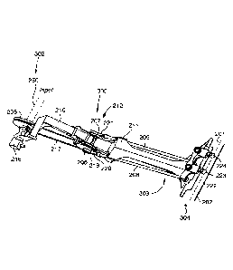
Figure 3 is a schematic view of a harvesting header 203, with a bifurcated
knife shown ¨
where the knife is divided into two similar, preferably substantially the
same, length knife
assembly sections 201, 202 at the front edge of the table. The direction and
stroke of travel
of the two knife assembly sections 201, 202 is shown at 'A' and 'W. The center
line of the
header is shown at 'CL'.
The general components of the knife drive assembly 204 of the present
invention (as shown
in Figures 3 ¨ 6) include: a drive paddle 211, a drive arm 210, a drive pulley
205, left and
11
CA 02951302 2016-12-06
WO 2015/188254
PCT/CA2015/000370
right eccentric wheels or discs 206 and 207 (referred to herein as an
"eccentric" or
"eccentrics" for simplicity), and left and right push rods 208 and 209. The
drive paddle 211
extends beneath the draper table of the harvesting header 203. The drive arm
210 extends
upward pivotally from the end of the drive paddle 211 towards the drive pulley
205. The
.. drive pulley 205 can be attached to the rotational power source on the
combine. The left and
right eccentrics 206 and 207 are connected to the left and right push rods 208
and 209. The
left and right eccentrics 206 and 207 are also connected, via the left and
right push rods 208
and 209, to left and right ball joints and bell cranks 223 and 224 at the
outward end of the
drive paddle 211, such that they will exert reciprocating horizontal movement
on the two
knife assembly sections 201 and 202.
Left and right push rods 208 and 209 are pivotally connected to the eccentrics
206 and 207,
such that the push rods are 180 out of phase. Accordingly, when the
eccentrics 206, 207 on
their shaft are rotated, by virtue of the connection point of each of the push
rods to their
respective eccentric, reciprocating movement in opposite direction, fully
synchronized, will
be provided. For example, knife assembly section 201 will reciprocally move
towards the
outer end of the header at the same time that knife section 202 moves towards
the opposite
end of the header. Ensuring that the knives of knife assembly sections 201,
202 are traveling
equal and opposite directions at all times is one of the key technical
benefits of the present
.. invention.
The embodiment shown in Figure 3 is illustrated in such a way that it would be
connected to
the right-hand side of the combine power unit, facing forward from the combine
operator
position. This is shown for demonstrative purposes ¨ it is as likely that in
most cases the
knife drive assembly would be connected to the right-hand side of the combine
power unit
but it will be understood that reflective manufacture of the knife drive
assembly of the
present invention for attachment to either the right-hand side or the left-
hand side of the
combine or other power unit is within the scope of the present invention.
12
CA 02951302 2016-12-06
WO 2015/188254 PCT/CA2015/000370
Bifurcated knife sections:
One of the key prior art issues which was desired to be addressed by the
creation of the
present drive assembly was to minimize vibration caused by the reciprocal
movement of the
knife on a harvesting header. The present invention may reduce or minimize
vibration by
providing two fully synchronized reciprocal drives for connection to two knife
sections 201,
202 extending in either direction from the point of drive attachment near the
center line of the
harvesting header 203. By providing two fully synchronized reciprocal drives
201, 202
which are 1800 out of phase with each other, vibration of the knives from
their reciprocal
movement is reduced to a minimum. The cooperation of a dual synchronized
reciprocal drive
with a bifurcated knife, whereby each bifurcated knife section will move
reciprocally in
synchronized out of phase movement as it is driven is explicitly contemplated
to comprise an
aspect of the present invention. Beyond just the unitary knife drive mechanism
of the present
invention, the overall concept of a dual synchronized reciprocal drive with
bifurcated knife
sections, which is directly mechanically driven by a mechanical drive in
accordance with the
remainder of the present invention is explicitly contemplated within the scope
of the present
invention.
The knife on a harvesting header may not be divided perfectly in half, since
it is explicitly
contemplated that the knife drive assembly of the present invention would be
mounted in
proximity but to one side of the center line of the header, extending forward
from the rear of
the header approximately parallel to the center line and approximately
perpendicular to the
orientation and direction of travel of the header. However, by bifurcating the
knife near the
center line of the header such that it is divided approximately in half, even
if not perfectly in
half, by provisioning two bifurcated knife sections 201, 202 of generally the
same size will
still result in the desired vibration minimization. Minimizing the vibration
of the device and
the knife is accomplished, in some embodiments, by ensuring that the two knife
assembly
sections travel in equal and opposite directions at all times.
13
CA 02951302 2016-12-06
WO 2015/188254 PCT/CA2015/000379
Unified mechanical element:
One of the primary benefits which is contemplated with respect to the present
invention, in
addition to the enhanced knife behavior which is achieved from the bifurcated
knife blade
operating in conjunction with the knife drive assembly, is that the knife
drive assembly of the
present invention can be manufactured as a reasonably streamlined and unitary
component,
which can be easily installed, replaced or swapped on the device. As is
stressed and outlined
herein, the fact that the knife drive assembly 204 can be manufactured in a
reasonably
compact and easily installed single component array, represents a significant
mechanical
enhancement over previous designs.
An embodiment of the knife drive assembly 204 of the present invention is
shown in Figures
4, 5, and 6. The knife drive assembly 204 includes a drive paddle 211, which
comprises the
front half of the drive structure and ensures a consistent geometry of the
drive package from
the rotational power input to the knife head. In a flex table application, the
drive paddle 211
will be pivoting structure underneath the draper deck and the connection point
for the floating
cutter bar. The drive paddle 211 may be manufactured in different lengths to
fit different
header tables, but as the drive paddle 211 is modified in length, the left and
right push rods
208, 209 will also need to be modified in length.
The drive paddle 211 may be connected to a drive arm 210. The drive arm 210
may be
pivotally interconnected to rotary bearing block assembly generally designated
212 for the
eccentrics 206, 207 at the rear of the drive paddle 211 and have a pivot
mechanism with a
locking pin 213. The pivot mechanism and the locking pin 213 allow for
adjustment during
installation of the unitary knife drive assembly 204, to move the drive arm
210 in the various
positions as dictated by the location of the combine's output shaft. Attached
at the rear end
215 of the drive arm 210 is a drive pulley 205 and a belt tensioner 216 may be
provided to
allow for the tensioning of the drive belt 217 once the knife drive assembly
204 is mounted
and appropriately positioned.
14
CA 02951302 2016-12-06
WO 2015/188254 PCT/CA2015/000370
Drive pulley 205 may be coupled to the output shaft of the combine harvester ¨
typically the
right-hand output shaft in the embodiments shown. The drive pulley 205 may be
sized in
diameter as required to achieve the correct knife speed in comparison or ratio
to the combine
output shaft speed. The drive pulley 205 engages, by way of a drive belt 217,
a driven pulley
218, which may be mounted with the left and right hand eccentrics 206, 207, as
described
below. When the input shaft from the combine applies rotational forces to the
drive pulley
205, the rotational forces are translated from the drive pulley 205, through
the belt 217, to the
driven pulley 218.
Near the pivoting point of attachment of the drive arm 210 to the drive paddle
211 is mounted
a bearing through which the eccentrics 206, 207 and the driven pulley 218 can
be connected.
As shown in Figures 4 to 6, the driven pulley 218 is co-mounted, geometrically
inside or
closer to the drive arm 210, to the right eccentric 206. The right eccentric
206, as will be
understood to those skilled in the art of mechanical design, may be a round
gear (or the like)
with a rotational attachment point to which an item can be rotatably attached
for the delivery
of eccentric motion as the eccentric 206 is rotated. The right eccentric 206
and the driven
pulley 218 need to be mounted such that the drive belt 217 does not inhibit
the rotation of the
right eccentric 206 or movement of the attached right push rod 208, and vice
versa. Attached
on the opposite side of the drive arm 210, coaxially with the driven pulley
218 and the right
eccentric 206, is a left eccentric 207.
Attached to the right eccentric 206 is a right push rod 208, which extends
forward along the
length of the drive paddle 211 towards the knife head attached thereto.
Similarly attached to
the left eccentric 207 is a left push rod 209, which similarly extends forward
along the length
of the drive paddle 211 towards the knife head thereof. In the embodiment
shown in Figures
3 to 6, right and left push rods 208, 209 are actually attached to their
respective eccentrics
206, 207 by a right connecting rod 220 and a left connecting rod 221,
respectively.
Connecting rods 220, 221 connect directly to the journal on the eccentrics
206, 207 to
CA 02951302 2016-12-06
WO 2015/188254 PCT/CA2015/000370
provide a stable point of rotation on one end and a fixing point for the
respective push rods on
the other end. It can be seen in Figures 4 to 6, that drive paddle 211
provides a retainer of
sorts for the right and left push rods 208, 209, as they are each moved by the
respective
eccentrics 206, 207.
At the distal end of the drive paddle 211, there is a knife end portion 222,
which is the portion
of the overall drive assembly 204 that connects to the bifurcated knife
assembly sections 201,
202. As can be seen, the right push rod 208 is connected to a right bell crank
223 on the
knife end portion 222. Bell crank 223 converts the fore and aft motion of the
right push rod
208 into a left and right motion at the knife end 222. In the embodiment
shown, the bell
crank 223 pivots on cartridge bearing. Similarly, the left push rod 209 is
connected to a left
bell crank 224 on the knife end 222, which will convert the fore and aft
motion of the left
push rod 209 into a left and right motion at the knife end 222. In the
embodiment shown, the
bell crank 224 pivots on cartridge bearings. As outlined elsewhere herein, the
eccentrics 206,
207 will be aligned in relation to each other and attached to their respective
push rods 208,
209 in such a way that the left and right motion at the left bell crank 224
will be
approximately equal and opposite to the left and right motion at the right
bell crank 223.
The right bell crank 223 will be connected to a right-hand bifurcated knife
section 201. and
the left bell crank 24 will be connected to a left-hand bifurcated knife
section 202. Various
precise means and connection of such cranks or similar motion conversion
apparatus to the
bifurcated knife sections 201, 202 will be understood by those skilled in the
art.
Dependent upon the size of the drive pulley 205, more or less adjustment may
be required to
put the required tension on the drive belt 217. One size of drive belt 217 can
be used for all
applications so the range of adjustment of this belt tensioner is quite wide.
If it was
alternatively desired to use belts that were closer in size to the combination
of pulleys etc.,
changing the drive belt 217 could also result in the functional need for less
ability to tension
the belt 217.
16
CA 02951302 2016-12-06
WO 2015/188254 PCT/CA2015/000370
Synchronized drive of two knives:
As is outlined elsewhere herein, bifurcating the knife on the harvesting
header 203 into two
knife assembly sections 201, 202 of similar length, and consistently applying
equal and
opposite reciprocal movement to each of those two knife assembly sections 201,
202 is a key
element of the present invention. Translation and transmission of eccentric
movement, 180
out of phase, to the two knife assembly sections 201, 202 from the rear of the
table, can be
done in a number of different ways by those skilled in the art of mechanical
design. It will be
understood that all such modifications or different approaches to achieving
the same
objective will be understood by those skilled in the art to be within the
scope of the present
invention.
Weight distribution:
The knife drive assembly 204 of the present invention may improve the weight
distribution of
assembled harvesting header 203 compared to prior art knife drives. Knife
drive assembly
204 is unitary and simpler in construction; thus, with the drive assembly 204
is light and can
be mounted relatively close to the center line of the harvesting header 203.
The unitary
construction has less weight to throw the harvesting header 203 off balance,
and applies less
torsional stress on the mounting hardware of the harvesting header 203 to the
combine (or
other power unit). The knife drive assembly 204, such as is disclosed herein,
is mounted in
proximity to the center line of a harvesting header 203 and provides opposed
reciprocal
movement to the bifurcated knife sections 201, 202 at the front of the header
table.
Accordingly, overall weight of the harvesting header 203 may be reduced and
the distal
weight at the distal end of the harvesting header 203 may also be reduced.
17
CA 02951302 2016-12-06
WO 2015/188254 PCT/CA2015/000370
In addition to reducing the weight of the harvesting header 203 at the distal
ends of the table,
by moving the heavier components of the knife drive assembly 204 to the rear
(inward side)
of the table, the weight of the drive assembly 204 at the cutter bar may be
reduced.
Single part knife speed adjustment:
Knife drive assembly 204 may allow for optimizing the knife speed for a wide
range of
applications. For example on different combines, the output shaft to which the
knife drive
assembly 204 can be coupled can have different output shaft speed. Center
mounted knife
drive assembly 204 allows for accommodation of varying output shaft speeds
without the
need to significantly alter the knife drive assembly 204. In this particular
embodiment, the
drive pulley 205 can be changed ¨ varied in diameter ¨ according to the common
output shaft
speed, in order to accomplish the desired gearing ratio and to achieve the
desired knife speed.
It may be sufficient to adjust the primary drive belt 217 (by tensioning or
loosening the drive
belt 217) to accommodate the variation in the diameter of the drive pulley
205. Accordingly,
the same drive belt 217 may be used for different output shaft speeds. As will
also be
understood to those skilled in the art, drive arm 210 may also be adjusted to
allow for
modification or positioning of the drive pulley 205 in an optimal location for
improved
alignment with the combine output shaft. Providing an adjustable drive arm
210, in
conjunction with the belt tensioner 216 and other related components, results
in the ability to
provide an angle adjustment to the positioning of the drive pulley 205 for
optimal alignment
with the combine output shaft.
Low profile at cutter bar:
One of the additional key benefits of the present invention is that knife
drive assembly 204,
when deployed on either a rigid or a flex table, does not interfere with crop
flow through and
over the knife onto the draper to the same extent as a least some known knife
drive
assemblies. With a very low profile at the cutter bar, the present invention
allows for a
18
CA 02951302 2016-12-06
WO 2015/188254 PCT/CA2015/000370
normal skid plate profile under the cutter bar which means the knife itself
can be positioned
as low as possible to the ground to perform at or near the ground in flex
cutting mode. In
addition to being deployable very close to the ground by virtue of the low
skid plate profile,
knife drive assembly 204 also allows for a low profile above the cutter bar
guards, lower than
the draper deck, which is needed to facilitate the crop flow onto the draper
after cutting. The
low profile at the cutter bar of knife drive assembly of the present invention
relative to the
other components of header 203, can be observed in the embodiment shown in
Figures 4
through 6.
Floating assembly for flex table:
Many harvesting headers deploy what is referred to as a flex table design, in
which portions
of the draper deck or the cutter bar float or flex relative to the header
frame to accommodate
deviations in the crop surface. Knife drive assembly 204 could be manufactured
to
.. accommodate a flex table design and with a flex table design coupled with
the low profile
provided at the front of the draper deck and in relation to the cutter bar
benefits may be
obtained and is one of the key benefits of the present invention.
Reduced mass at distal ends of the header:
Since the mechanical drive elements for the knife drive assembly 204 are
located at or
proximate the transverse center of the header table 214, the remainder of the
mass and the
end struts of the header 203 can be reduced in width and mass for optimal crop
dividing
performance. Positioning of knife drive assembly 204 at or proximate the
center of the table
eliminates the requirement for wide end struts on the header to encompass a
drive assembly.
A narrow end strut reduces the impact of the strut on the crop outside the
range of the cutting
knives as less crop material is damaged as the structure is pushed through it.
Knife drive
assembly 204 may allow for a header table to have the absolute minimum
structural width
required for the end struts to be reliable and stable.
19
CA 02951302 2016-12-06
WO 2015/188254
PCT/CA2015/000370
Header with dual reciprocating knife sections:
A harvesting header such as header 203 which employs a center mounted low-
profile knife
drive assembly 204, and provides fully synchronized and 180 out of phase
movement of two
bifurcated knife assembly sections 201, 202 is contemplated within the scope
of the present
invention. Rotational force from the combine is translated and applied to the
left and right
eccentrics 206, 207. The left and right pushrods 208, 209 (interconnected to
eccentrics 206,
207), in conjunction with low-profile bell crank devices 223, 224 attached to
the bifurcated
knife sections 201, 202, can result in the two knife assembly sections 201,
202 traveling in
equal and opposite directions.
The deployment of the knife drive assembly 204 and dual reciprocating knife
assembly
sections 201, 202 in accordance with the present invention, could be modified
for use on
.. many different types of harvesting header designs. It will be understood
that all such
modifications to implement the present invention in those type of headers are
all
contemplated within the scope of the present invention would not be conceived
to depart
from the general scope and intention hereof.
By way of overview with reference again to Figures 3 to 6, a first force and
movement
conversion mechanism designated 300, is operable to convert a rotational force
from a
rotational power source 302 (such as the output shaft 250 (Figure 4) provided
on a
propulsion unit 10 of a piece of agricultural equipment such as a combine
harvester or
swather (Figure 1) to drive at least one longitudinally moving member (such as
push rods
208, 209) in reciprocating longitudinal movement. A second force and movement
conversion
mechanism 304 is operable to convert the reciprocating longitudinal movement
of the at least
one longitudinally moving member to drive at least one knife (such as the
knives and knife
blades in knife assembly sections 201 or 202) in transverse reciprocating
movement that may
be substantially perpendicular to the longitudinal reciprocating movement.
CA 02951302 2016-12-06
WO 2015/188254 PCT/CA2015/000370
With reference to harvesting header 203, knife drive assembly 204 is
configured to receive
rotational power from rotational power source 302 such as the power take off
shaft 250 of a
propulsion unit 10 of a piece of agricultural equipment. Knife drive assembly
204 is operable
and configured to convert the rotational power and force from the rotational
power source
into longitudinal reciprocating motion of the push rods 208, 209, and to
translate the
longitudinal reciprocating motion of the push rods 208, 209 into transverse
reciprocating
motion. The knife drive assembly 204 is further configured and operable to
utilize the
transverse reciprocating motion to drive one or more knives (e.g. knife
assembly sections 201
and 202) in transverse reciprocating motion (as shown by arrows A and B in
Figure 3). The
transverse moving and oriented knives / knife assembly sections 201, 201 can
be used to cut
crops in a field when the header 203 is moved in a longitudinal direction in
the field by a
propulsion unit 10.
Now with reference to Figures 7 to 16, additional details of the construction
and operation of
a harvesting header 203 and its knife drive assembly 204 are provided. As
indicated above,
knife drive assembly 204 may include drive pulley 205, eccentrics 206, 207,
push rods 208
and 209, bell cranks 223 and 224, and knife assembly sections 201 and 202 that
have at least
one knife blades and typically a plurality of transversely oriented blades..
Drive pulley 205 is
connected to an output shaft 250 from a piece of equipment such as the
propulsion unit 10 of
a combine harvester or swather (Figure 7). Output shaft 250 is configured to
interface and
couple with drive pulley 205 and is and operable to drive pulley 205 in
rotation about a
pulley shaft 251 having an axis, with the shaft 251 being mounted and held in
a suitable
bearing device. Pulley shaft 251 passes through drive pulley 205 and extends
into a gear box
254. Output shafts 250 and 263 may each be configured as telescopic slip
shafts that will
allow for a limited amount of relative movement laterally and longitudinally
if and when
knife drive assembly 204 moves relative to the output shaft 250 of the combine
and input
shaft 259, to accommodate some mis-alignment that may occur during operation.
Gear box
254 converts the transversely oriented rotation of shaft 251 to the rotation
of output drive
21
CA 02951302 2016-12-06
WO 2015/188254 PCT/CA2015/000370
shaft 263 oriented in a longitudinal direction. With reference to Figure 8,
output shaft 263
may be operably coupled to input shaft 259. Input shaft 259 may be connected
to a drive
mechanism for a draper canvas 403 of a draper assembly 407.
Eccentric 206 is coupled to the drive pulley 205 by a drive belt 217 and
receives the
rotational power from the rotational power source through the drive belt 217.
The drive belt
217 thus rotates the eccentric 206. Push rod 208 is coupled to the eccentric
206 and receives
rotational power from the eccentric 206. Eccentric 206 thus moves the push rod
208 in
longitudinal motion. A bell crank 223 is coupled to push rod 208 and to the
knife section 201
and receives longitudinal forces from push rod 208. Bell crank 223 converts
the longitudinal
forces and longitudinal reciprocating movement from push rod 208 into
transverse forces and
transverse reciprocating motion of knife assembly section 201, as will
explained further
hereinafter.
In the embodiment illustrated in Figures 7 to 16, the rotational power
provided by an output
shaft 250 can be used to transversely move both left and right knife assembly
sections 201,
202. Drive pulley 205 is coupled to a rotary bearing block assembly 212 that
includes left
and right eccentrics 207, 206 mounted for rotation on a common axle about a
common
transversely oriented axis. Drive belt 217 thus rotates both the right and
left eccentrics 206,
.. 207. Right eccentric 206 and left eccentric 207 may be locked relative to
each other to rotate
180 degrees out of phase with each other. Right and left push rods 208, 209
are coupled to
the right and left and right eccentrics 206, 207 respectively. Left eccentric
207 moves the left
push rod 209 in longitudinal reciprocating motion, and the right eccentric 206
moves the right
push rod 208 in longitudinal reciprocating motion. Right and left bell cranks
223, 224 are
coupled to outward end portions of the right and left push rods 208, 209,
respectively, and
receive alternating longitudinal forces from the push rods 208, 209,
respectively. The right
and left right bell cranks 223, 224 translate the longitudinal alternating
forces into transverse
alternating forces causing transverse reciprocating motion of the right and
left knife assembly
sections 202, 201, respectively.
22
CA 02951302 2016-12-06
WO 2015/188254
PCT/CA2015/000370
The rotational power that is converted to reciprocating longitudinal movement
of the push
rods 208, 209 may be operable to move right and left knife assembly sections
202, 201
respectively in opposing transverse reciprocating motion by maintaining the
left and right
push rods 208, 209 in an out-of-phase relationship. For example, left push rod
209 may be
coupled to the left eccentric 207 at a nominal 0 degrees, and right push rod
208 may be
coupled to the right eccentric 206 at 180 degrees out of phase relative to
left push rod 209.
Left and right push rods 208, 209 would thus move in longitudinal movement at
180 degrees
out-of-phase relative to one another. Such an arrangement helps to reduce
vibrations
associated with transversely moving the knife sections 201, 202 due to
operating in
equivalently opposite directions. Vibrations produced by movement of the left
and right
eccentrics 207, 206, the left and right push rods 209, 208, and the left and
right knife
assembly sections 201, 202, will cancel out, or at least be substantially
reduced. Reduced
vibrations are expected to enhance both reliability (less downtime and less
maintenance) and
also increase operator comfort during use.
More details of knife drive assembly 204 are now provided with reference to
Figures 3, and 7
- 9. Figure 3 illustrates a schematic view of the bottom of the harvesting
header 203
deploying the knife drive assembly 204. The width 'W' of the harvesting header
203 in a
transverse direction is defined by the spacing of end struts 290, and may in
many example
embodiments range from 30 feet to 45 feet. Also shown in Figure 3 is the
center line 'CL' of
the harvesting header 203, which is at the halfway point of the transverse
width of the
harvesting header 203.
Knife drive assembly 204 generally extends from an area proximate inner
transverse side 291
of the header 203 to an outward side 293 of the harvesting header 203 (as
shown for example
in Figures 3 and in Figure 7A). In one embodiment (not shown), knife drive
assembly 204
extends substantially along or transversely straddles to some extent the
longitudinal center
line CL of the harvesting header 203. In other embodiments, knife drive
assembly 204
23
CA 02951302 2016-12-06
WO 2015/188254
PCT/CA2015/000370
extends longitudinally but is entirely spaced transversely a relatively short
distance to one
side of the center line CL of harvesting header 203 (i.e. either to the right
or left of the center
line).
Knife drive assembly 204 may include a longitudinally extending drive paddle
211 and a
longitudinally extending drive arm 210 each of which may be made from one or
more
suitably strong materials such as steel. Drive paddle 211 and drive arm 210
may be fixedly
or pivotally inter-connected to each other at adjacent or overlapping end
regions,
interconnected with rotary bearing block assembly 212 as will he explained
further
hereinafter. Drive arm 210 may have an integrally formed, transversely
extending, support
plate region 295. Support plate region 295 may have a pair of spaced,
orthogonal plate
extension portions 294a, 294b (see Figures 13 and 14) that may be
interconnected to a pair of
extension plates 292a, 292b with a bolt 320 passing through apertures in
plates 292a, 292b,
294a, 294b and being held in place by a nut 321. Plates 294a, 294b may pivot
relative to
plates 292a, 292b and may be used to support gear box 293, shaft 251, drive
pulley 205 and
output shaft 263 (see Figures 8, 13 and 14). The ability to pivot plates 294a,
294b relative to
plates 292a, 292b can also facilitate adjustment of the tension/tightness of
drive belt 217
depending upon the size of the drive pulley 205 that is being utilized. It
will be noted that
this assists in enabling knife drive assembly 204 to be readily configured /
modified to fit one
of several different types/brands/models of combine harvesters or other pieces
of agricultural
equipment by being able to easily vary the size/diameter of the drive pulley
205 that is
employed.
The longitudinally outward end of knife drive assembly 204, and in particular
the outward
knife end portion 222 of drive paddle 211, is mounted to the cutter bar
assembly 405 by
securing a transversely extending cutter bar mounting plate portion 279 of
drive paddle 211
(that may be integrally formed at the outward end of drive paddle 211) near
the outward side
293 of the header 203 directly to a cutter bar 280 (Figures 7 and 7A) by
nuts/bolts 297 or
24
CA 02951302 2016-12-06
WO 2015/188254 PCT/CA2015/000370
other releasable attachment mechanisms. Thus, knife drive assembly 204 can be
supported
on header 203 at a first location, proximate cutter bar assembly 405.
Knife drive assembly 204, and in particular drive paddle 211, may also be
supported at a
second location at a longitudinal distance from the cutter bar 280 towards the
inward side 291
of the header 203 by securing drive paddle 211 to elements of the support
frame of header
203. With particular reference to Figures 8 and 9, drive paddle 211 may be an
entirely rigid
portion of the support frame (which also includes drive arm 210) that supports
components of
knife drive assembly 204. The parts forming drive paddle 211 may be fixedly
interconnected
to each other such as for example by welding. Drive paddle 211 may nclude a
pair of
laterally spaced part, parallel and longitudinally oriented plates 281a, 281b
which may be
attached such as with releasable bolts 283a, 283b (Figures 8 and 9) to
corresponding frame
strut plates 282a, 282b that form part of the header frame supporting sub-
structure. Drive
paddle 211 can also pivot on and relative to frame strut plates 282a, 282b
about a transverse
axis defined by transversely oriented bolts 283, 283b. Pivoting drive paddle
211 is required
on a so-called flex table or draper where the cutter bar assembly 405 will
move vertically up
and down independently of the header frame. On a flex draper table header, it
can be
expected that there may be a relative movement of up to 9 inches of the cutter
bar 280 up and
down relative to the support fame of header 203. A limiting strap (not shown)
may be
provided proximate the outward end of drive paddle 211 attached to a strut
forming part of
the header frame and may attach to the outward end of drive paddle 211 with a
pin. The
limiting strap may be provided to limit the range of movement of the end of
paddle 211 to a
maximum of 9 inches from the frame strut. The pivot connection of the drive
paddle 211 will
permit knife drive assembly 204 as a whole to be re-oriented as the cutter bar
280 moves up
and down relative to the frame of the header 203. In operation, drive arm 210
will be fixedly
connected to drive paddle 210 and so when drive paddle 211 pivots at this
second location,
then so will drive arm 210 also pivot. However, since the length of drive arm
210 is typically
much shorter than the length of drive paddle 211, the inward end of drive arm
210 where the
connection to output shaft 250 is located will not rotated by such a great
distance (eg. about
CA 02951302 2016-12-06
WO 2015/188254
PCT/CA2015/000370
less than half ¨ such as only 4 inches maximum). This amount of pivoting
movement of
drive arm 210 can be accommodated at the inward end of drive arm 210. .
In a rigid table header, there will be substantially no relative
upward/downward movement of
the cutter bar 280 relative to the frame of the header and so there will be
substantially no
.. relative pivoting of the drive paddle 211 relative to frame strut plates
282a, 282h about the
transverse axis defined by transversely oriented bolts 283, 283b.
The result of the foregoing construction of knife drive assembly 204, is that
when it is desired
to remove or install a knife drive assembly 204 from header 203 this can be
accomplished in
a relatively easy manner by releasing/attaching bolts 297a/b, 283a/b at these
two locations of
drive paddle 211, so that knife drive assembly 204 can be removed/installed as
a complete
single unit. The removal process would also include disconnecting the drive
shafts 250 and
263 and the outer end of the drive paddle 211 will be disconnected (such as
being unbolted)
from cutter bar assembly 405.
When knife drive assembly 204 is detached from header 203, it can be properly
set up
including providing the necessary timing adjustments that may be required to
ensure the
correct operation of knife drive assembly 204 as explained herein, including
the appropriate
timing adjustments to the strokes of the eccentrics 206, 207 and their push
rods 208, 209.
.. Typically, no further adjustments of timing of the eccentrics 206, 206 and
their respective
push rods 208, 209 is required, once the knife drive assembly 204 has been
installed on
header 203. With respect to setting the proper timing adjustment, it will be
noted in
particular in Figure 13 that eccentric 206 / driven flywheel pulley 218 and
eccentric 207 have
transverse apertures passing there through. A
corresponding aperture 324 through an
extension plate 325 that is part of rotary bearing assembly 212 may also be
provided, such
that if a pin is passed through each of the apertures 323 in eccentric 206 /
driven flywheel
pulley 218 and eccentric 207 and through aperture 324 in plate 325, then a
person will know
that the timing of the relative rotations of the eccentrics 207, 208 is
correct. To complete the
timing adjustment, a person can, with front faces of the bell cranks 223, 224
and their
26
CA 02951302 2016-12-06
WO 2015/188254
PCT/CA2015/000370
respective knife bearing heads 225, 226 being parallel and aligned with each
other, the
outward ends of push rods 208, 209 can be threaded inwards/outwards until
there is a snug
fit. This will set the timing on all components from the eccentrics 206, 207
to the knife
bearing heads 225, 226.
With particular reference again to Figures 7 and 7A, header 203 may also
include draper deck
assembly 402 (sometimes also referred to as a draper table) and cutter bar
assembly 405, both
of which may be mounted in a conventional manner to the frame of the header
203. As can
be seen in Figures 7 and 7a, some sub-frame components (collectively numbered
289) extend
transversely and may provide at least partial support draper deck assembly
402. Draper deck
assembly 402 may include rollers such as roller 409 (see Figure 13) mounted in
a
conventional manner to support a draper canvas 403. Draper canvas 403 may
include
transverse slats 404. Figure 7A shows part of harvesting header 203 without
the draper
canvas 403 to illustrate the entirety of knife drive assembly 204, which lies
underneath draper
table 402, and extends from the inward side 291 of header 203 to the outer
side 293 of header
203.
With reference again to Figure 1 and 4-6, output shaft 250 from the propulsion
unit 10
(Figure 1) may be oriented generally perpendicular to knife drive assembly
204. Output shaft
250 has a proximal end attached to drive pulley 205 (e.g. by quick release
splines, a nut and
bolt, or by other attachment means known in the art) and a distal end
configured to couple
drive pulley 205 to output shaft 250. With reference to Figures 12 and 14,
drive pulley 205
may comprise an outer drive disc portion 1205, which may be bolted to a
cylindrical hub
section 1206. Hub section 1206 may be fixedly attached to shaft 251 and rotate
with shaft
251, which may be supported by bearings (not shown but included in the
gearbox). Outer
disc section 1205 may be made from a relatively soft metal material such as
grey iron casting
material whereas inner hub section 1206 may be made from a stronger material
such as a
strong steel. This can permit the larger diameter portion of the drive shaft
205 to dampen
27
CA 02951302 2016-12-06
WO 2015/188254
PCT/CA2015/000370
vibrations, while the central hub portion has the enhanced strength of a
material like steel,
and which also allows it to act a suitable bearing surface.
Drive pulley 205 is operably coupled to output shaft 250. This may be
accomplished for
example as follows: Output shaft 250 may be provided with a flange that may be
bolted on
the connection side to drive pulley 205. On the side connecting to the
propulsion unit 10,
there may be provided a splined shaft with a quick connect coupler, of the
type known in the
art. It should be noted that the connection of shaft 250 to drive pulley 205
may be the only
connection that includes bolts. The other shaft connections may be spline
shaft quick coupler
connections. Such connections provide ease of service and also permit some
degree of
flexibility since they may be telescopic to allow for adjustment / limited
movement.
Output shaft 250 is thus configured and operable to couple drive pulley 205 in
rotation about
shaft 251, which passes through drive pulley 205 and extends into a gear box
254. Gear box
254 converts the transversely oriented rotation of shaft 251 to the rotation
of an output drive
shaft 253 oriented in a longitudinal direction. With reference to Figure 8,
output shaft 253
may be operably coupled to input shaft 259. Input shaft 259 may drive a drive
mechanism
for a draper canvas 403 of a draper assembly 407.
As indicated above, also included as part of harvesting header 203 is draper
table 402. In one
example embodiment, draper table 402 has a draper canvas 403 made of
rubberized polyester
and has a width of about 42 inches. The draper canvas 403 has slats 404
extending from a
first end to a second end of the draper canvas 403. The slats 404 may be
oriented generally
perpendicular to the length of draper canvas 402. In one embodiment, the slats
404 are made
of fiberglass reinforced rubber slats.
Draper table 402 collects crop material that has been cut by the knife
assembly sections 201,
202. The draper table 402 is also divided into two transverse sections. Each
section moves
crop transversely from the sides towards the center line 'CL' of the
harvesting header 203;
28
CA 02951302 2016-12-06
WO 2015/188254
PCT/CA2015/000370
thereby transporting the collected crop into a table opening 406 where it can
be handled by a
center draper canvas 408. In addition to draper canvas 403, a second draper
canvas (not
shown in Figure 7) like draper canvas 403 and supported in a similar manner,
is included at
the opposite side of the table opening 406, which functions in substantially
the same manner
as draper canvas 403 but moves the collected crop in the transversely opposite
direction to
table opening 406. Once the cut and collected crop reaches the table opening
406 the cut
crop material can be deposited onto central draper canvas 408 which may move
the collected
crop inwards towards and into engagement with a central feed auger 410 for
further
processing into the combine harvester (not shown in Figure 7). A transversely
oriented
hinged door 411 may be provided adjacent to center draper canvas 408 and can
be opened
and closed in order to periodically remove debris / stuck crop material in the
vicinity of the
center draper canvas 408.
An overview of the functions performed by knife drive assembly 204 is now
provided with
reference to Figures 4 ¨ 6, showing knife drive assembly 204 detached from the
harvesting
header 203.
Knife drive assembly 204 may be considered to have three functional sections:
(1) a
rotational power interface 302; (2) a rotational-to-longitudinal force /
movement converter
300; and (3) a longitudinal-to-transverse force / movement converter 304. The
mechanical
components corresponding to these three functional sections are positioned
along the length
of the knife drive assembly 204, with the rotational power interface 302 at a
first end
proximate the output from source of rotational drive and extend from the first
end to a medial
region, the components corresponding to rotational-to-longitudinal converter
300 are located
in a medial region, and the components for the longitudinal-to-transverse
converter 304
extend from that medial region to but are mostly concentrated at a second end
of the knife
drive assembly located opposite the first end and are proximate the cutter
blade assembly
405.
29
CA 02951302 2016-12-06
WO 2015/188254
PCT/CA2015/000370
The rotational power interface 302 includes (amongst other things) the drive
pulley 205, a
driven pulley 218, a drive belt 217, and a belt tensioning! adjustment
mechanism 216.
With particular reference to Figure 14, belt tensioning mechanism 216 may
include a pivot
mounting structure for drive pulley 205 that includes plates 292a, 292b and a
pivot bolt 320.
A threaded rod 298 with adjustment nut 299 forms the adjustment point and
mechanism. Rod
298 is pivotally connected at one end to a pin 326 that extends between plates
292a, 292b.
The opposite end of rod 298 passes through a threaded block 327 that is held
between
extension plates 294a, 294b. By adjusting the amount of extension of rod 298
through
threaded block 327, the rotational angular position of the drive pulley 205
relative to drive
arm 210 can be modified about an arc. By adjusting the angular position of the
drive pulley
205 relative to drive arm 210, the tension of the drive belt 217 can be
adjusted and set.
Additionally, the pivoting movement of drive pulley 205 allows for drive belts
to be
removed/installed/replaced, including providing drive belts of different
configurations/lengths.
The rotational-to-longitudinal converter 300 includes the rotary bearing
assembly 212 which
includes (amongst other things) the right and left eccentrics 206, 207 (which
provide "Pitman
eyes"), the right and left push rods 208, 209, and left and right connecting
rods 220, 221
(which act as "Pitman arms").
With reference also to Figures 14-16, the longitudinal-to-transverse
force/movement
converter 304 also includes (amongst other things) a knife end portion 222 of
the drive
paddle 211, which is interconnected to components of the knife assembly
sections 201, 202
such as knife head bearings 255, 256, and knife heads 257, 258. Knife end
portion 222 of
drive panel 211 has mounted to it right and left bell cranks 223, 224, right
and left knife
bearing heads 226, 225, and left and right ball joints 227, 228 (Figures 14-
16).
CA 02951302 2016-12-06
WO 2015/188254
PCT/CA2015/000370
Returning again to Figures 4 to 6, rigid drive arm 210 extends generally from
a first end of
the knife drive assembly 204 toward the central / medial region of the knife
drive assembly
204.
At an inward end, drive arm 210 is inter-connected with drive pulley 205 as
described above.
At the opposite end, drive arm 210 is attached to plates 270a, 270b that are
interconnected
with a pivot pin connection 272 to drive paddle 211 and rotary bearing
assembly 212. As is
evident from Figures 13 and 14 in particular, a pivot pin 272 passing through
plates 270a,
270b, and corresponding end flanges 273a, 273b at the end of drive arm 210
provides for a
pivotal connection between drive arm 210 and paddle 211. Drive arm 210 may
also be
provided with a transversely oriented cylindrical tube 265 that may be
attached such as by
welding to an upper surface area 211a (Figure 13) of drive arm 210. Drive arm
210 can be
pivoted to, and locked at, one of several specific angular positions relative
to drive paddle
211 and rotary bearing assembly 212. The specific desired operating angle of
drive arm
relative to drive paddle 211 and bearing assembly 212 can be selected and then
locked in
place by use of a locking pin 213 (Figure 13) that may be received through one
of serveral
pairs of opposed apertures such as apertures 274a, 247b and through aligned
hollow tube 265
when the tube 265 is aligned with the pair of opposed apertures. The
pivoting are of drive
arm 210 relative to paddle 211 about pivot pin 272 is determined by the
position of locking
pin 213 as it extends between specific apertures in plates 270a, 270b. Several
sets of
apertures 274a, 274b may be provided so that the range of pivoting motion /
position of drive
arm 210 relative to drive paddle 211 may be selected. A plurality of opposed
pairs of
apertures 274a, 274b can be provided to accommodate alternate configurations
of different
types/brands/models of propulsion units 10 to which a header 203 having knife
drive
assembly 204 can be attached. A set of apertures can also be provided to
accommodate
transportation of the header 203 to which the knife drive assembly 204 is
attached, when the
header 203 is detached from the propulsion unit 10 and is being transported.
31
CA 02951302 2016-12-06
WO 2015/188254
PCT/CA2015/000370
The left and right eccentrics 207, 206 and the driven pulley 218 form part of
rotary bearing
block assembly 212, as will be described further hereinafter. Drive paddle 211
has first and
second ends, which extend from the center/medial region of drive assembly 204,
to a second
end region of the knife drive assembly 204, respectively. In some embodiments,
drive paddle
211 may be substantially or at least in part, a vertically rigid 1-beam shaped
structure. The
second outer end of drive paddle 211 can be attached with releasable
attachment devices to
the cutter bar 280 of cutter bar assembly 405.
The rotational power interface 302 receives an input rotational force from the
output shaft
250 from the propulsion unit 10 (Figure 1) and creates a rotational force at
the left and right
eccentrics 207, 206. In the rotational power interface 302, the drive bell 217
is attached to,
and engagingly extends between, the drive pulley 205 and the driven pulley
218. The driven
pulley 218 is operably interconnected to the left and right eccentrics 207,
206 on a common
rotational axis, as will be explained hereafter. Drive belt 217 thus couples
drive pulley 205 to
driven pulley 218 and to left and right eccentrics 207, 206. In operation, the
rotational power
interface 302 of knife drive assembly 204 receives rotational power through
the output shaft
250, thereby rotating the drive pulley 205. Drive pulley 205 rotates drive
belt 217, which in
turn rotates driven pulley 218 together with eccentrics 207, 206.
The rotational-to-longitudinal force converter 300 converts the rotational
forces at driven
pulley 218, into longitudinal forces at the left and right push rods 209, 208.
In the rotational-
to-longitudinal force converter 300, left and right and right eccentrics 207,
206 are attached to
left and right connecting rods 221, 220 respectively.
In particular, a first end of each of left and right connecting rods 221, 220
interface with and
are inter-connected to respective off-center rotating eccentric wrist pins
338, 339 (Figure
10A) of each of the eccentrics 206, 207. The rotation of eccentrics 207, 206
therefore causes
the connecting rods 221, 220 to move up and down, and longitudinally fore and
aft (ie inward
and outward) along the length of drive paddle 211 to generate longitudinal
alternating forces.
32
CA 02951302 2016-12-06
WO 2015/188254
PCT/CA2015/000370
Furthermore, a first end of left and right push rods 209, 208 is attached
(e.g. by bolt and nut,
or by other known attachment means) to a second end of the left and right
connecting rods
221, 220. The rotation of the eccentrics 207, 206 therefore also causes push
rods 209, 208 to
move up and down the along the length of the drive paddle 211 and
longitudinally to generate
longitudinal alternating forces.
The longitudinal-to-transverse force/movement converter 304 converts the
longitudinal forces
and reciprocating movement of left and right push rods 209, 208 into
alternating transverse
forces at, and reciprocating movement of, the left and right knife bearing
heads 225, 226,
knife head bearings 256, 255 and left and right knife heads 258, 257,
respectively. The left
and right bell cranks 224, 223 translate the longitudinal alemating forces of
the left and right
push rods 209, 208, respectively, into alternating transverse forces. The
transverse forces
engage the left and right knife bearing heads 225, 226. Knife bearing heads
225, 226 deliver
the transverse forces through knife head bearings 256, 255, to left and right
knife heads 258,
257, respectively, thereby moving the left and right knife assembly sections
201, 202 in
transverse reciprocating motion.
More details of various components of one embodiment of the knife drive
assembly 204 are
now provided with particular reference to Figures 8 ¨ 18. Drive pulley 205 is
circular and
may have a grooved outer edge to secure the drive belt 217 in position. In one
embodiment,
the drive belt 217 is a v-belt or micro-grooved belt. By providing such a belt
with some level
of slippage, the belt 217 acts as a clutch mechanism and can reduce the risk
of damage if
another part of the drive assembly mechanism were to lock up / seize. Driven
pulley 218 may
configured similarly to the drive pulley 205, having a circular shape and a
grooved outer edge
to secure the drive belt 217 in position. Drive belt 217 extends between drive
pulley 205 and
driven pulley 218, thereby causing the driven pulley 218 to rotate about a
transverse axis
when the drive pulley 205 receives a rotational force and rotates about a
substantially parallel
transverse axis.
33
CA 02951302 2016-12-06
WO 2015/188254
PCT/CA2015/000370
The ratio of the diameter of the drive pulley 205 to the diameter of the
driven pulley 218
influences the speed of rotation of the driven pulley 218 and thereby
influences the speed of
transverse reciprocating motion of the knives of the knife assembly sections
201, 202; i.e. the
cutting speed. Accordingly, adjusting the diameter ratio of the two pulleys
will influence the
cutting speed. Such an adjustment is most useful if the rotational power
received at the input
shaft 250 from the external rotational power source has a fixed speed. In some
embodiments,
the drive pulley 205 is user replaceable, thereby allowing users to alter the
cutting speed
easily. The size/external diameter of drive pulley 205 can be selected to
provide a suitable
rotational speed when connected to output shaft 250. For example, the diameter
of drive
pulley 205 may be selected to achieve a rotation speed of in the range of
approximately 550
rpm and 620 rpm.
Turning now to rotary bearing block assembly 212, this provides the mechanism
to convert
the rotation of the driven pulley 218 to provide longitudinal reciprocating
movement of the
push rods 208, 209. In overview, the rotary bearing block 212 comprises a
crankshaft
mechanism interconnected to and integrated with pitman arm/eye mechanism. With
particular reference to Figures 10 and 10A, rotary bearing block assembly 212
includes the
left eccentric 206 and the right eccentric 207, along with driven pulley 218.
Left eccentric
206 is formed as a combined integrally connected flywheel 360 / driven pulley
218. The left
eccentric 206 also includes a first hub 337. Right eccentric 207 is formed as
a flywheel 335
with a hub 336. Rotary block assembly also includes a rotary bearing journal
332 which
functions a crankshaft and has rotary bearings 342, 343.
Hub eccentric 337 is mounted to flywheel 360 / driven pulley 218 combination
by insertion
of the inner recessed portion 361 into an opening in flywheel 360 / driven
pulley 218 with
bolts 341 secured through the outer periphery of hub eccentric 337 into
threaded apertures in
a flange (not shown) in fly wheel 360 / driven pulley 218. Similarly hub
eccentric 336 is
mounted to fly wheel 335 by insertion of the inner recessed portion 362 of hub
eccentric 336
34
CA 02951302 2016-12-06
WO 2015/188254 PCT/CA2015/000370
into an opening in flywheel 335 and with bolts 342 secured through the outer
periphery of
hub eccentric 336 into threaded apertures in a flange (not shown) in flywheel
335.
The combination of hub eccentric 337 and flywheel 360/ driven pulley 218 are
mounted on a
raised saw tooth outer circumferential portion 342 of the rotary bearing
device 332. The saw
tooth portion 342 of bearing device 332 will mate with an interior saw tooth
profile in an
inner surface of hub 337 connected to flywheel 360 / driven pulley 218. A pin
354 is
provided to engage the saw tooth connection to provide the proper positioning
of hub 337
with bearing device 332. Similarly the combination of hub eccentric 336 and
flywheel 335
are mounted on a raised saw tooth outer circumferential portion 343 of the
rotary bearing
device 332. The saw tooth portion 343 of bearing device 332 will mate with an
interior saw
tooth profile in an inner surface of hub 336 connected to flywheel 335. A pin
352 is
provided to engage the saw tooth connection to provide the proper positioning
of hub 336
with bearing device 332. By employing pin 354 with the saw tooth connection of
hub 337
and pin 352 with the sawtooth connection of hub 336, it can be ensured that
hub 336 is
positioned in a 180 degrees out of phase relationship to hub 337.
A main axle bolt 330 passes through hub 337 and flywheel 360 / driven pulley
218
combination and through hub 336 and flywheel 335, within rotary bearing 332.
Axle bolt
330 joins with axle nut 344 to axially hold the entire combination of
components together
with and when the rotary bearing 332 mounted within bearing housing 331. Seals
333a, 333b
and seal washers 355, 356 are provided for roller bearings 342, 343. Bushings
353, 351 may
also be provided to assist with suitable alignment between hubs 337, 336 and
the rotary
bearing journal 332.
The combination of hub 337 and flywheel 360 / driven pulley 218, and hub 336
and flywheel
335, along with rotary bearing 332 are thus fixedly connected together and
rotate as one unit
within bearing housing 331. This combination functions as a crankshaft to
drive the
movement of the push rods 208, 209.
CA 02951302 2016-12-06
WO 2015/188254 PCT/CA2015/000370
Hub eccentrics 336, 337 and their corresponding flywheels 335 and 360 (along
with driven
pulley 218) will be rotated together with rotary bearing 332 about the
longitudinal axis of the
axle bolt 330, supported for rotation with axle bolt 330 and rotary bearing
332, within
.. housing 331, when drive belt 217 is caused to move by drive pulley 205.
A pitman arm/eye mechanism is provided for each hub 336, 337. With reference
to both
Figures 10 and 10A, for hub 337, a bearing 345 for the pitman eye is provided
and which is
mounted on wrist pin 338. The outer race of bearing 345 is held in place by a
snap ring 334.
.. The inner race of bearing 345 is held in place by a bolt 346 which passes
through a washer
347 and is received in a threaded aperture in wrist pin 338. The connecting
rod 221 (which
functions as a pitman arm) has an end with a circular aperture that is mounted
on bearing 345.
The outer race of bearing 345 is fixedly connected to the connecting rod 221.
The inner race
of bearing 345 is fixedly connected to the wrist pin 338. Thus, when wrist pin
338 rotates,
.. the outer race of the bearing 345 with the cnd of connecting rod 221
fixedly connected
thereto, will rotate relative to the inner race of bearing 345 and wrist pin
338.
The movement of hub eccentric 337 will cause an off-axis wrist pin 338 to
rotate around in a
planetary motion about the axis of the main axle bolt 330. It will be
appreciated that as pin
338 rotates around the axis of main axle bolt 330, connecting rod 220 will
undergo
reciprocating longitudinal motion that by virtue of the connection with push
rod 208 imparts
reciprocating longitudinal motion on push rod 208.
For hub 336, a bearing 348 for the pitman eye is provided and which is mounted
on wrist pin
.. 339. The outer race of bearing 348 is held in place by a snap ring 335. The
inner race of
bearing 348 is held in place by a bolt 349, which passes through a washer 350
and is received
in a threaded aperture in wrist pin 339. The connecting rod 220 (which also
functions as a
pitman arm) has an end with a circular aperture that is mounted on bearing
348. The outer
race of bearing 348 will be fixedly connected to an end of the connecting rod
220. The inner
36
CA 02951302 2016-12-06
WO 2015/188254 PCT/CA2015/000370
race is fixedly connected to the wrist pin 338. Thus when wrist pin rotates,
the outer race of
the bearing 345 with connecting rod 221 fixedly connected thereto, will rotate
relative to the
inner race of bearing 345 and wrist pin 338.
Similarly, the movement of hub eccentric 336 will cause and off-axis pin 339
to rotate around
in a planetary motion about the axis of the main axle bolt 330. It will then
be appreciated
that as pin 339 rotates around the axis of main axle bolt 330, connecting rod
221 209 will
undergo reciprocating longitudinal motion that by virtue of the connection
with push rod 209
imparts reciprocating longitudinal motion on push rod 200.
With reference to Figure 10, rotary bearings 342, 343 may include oil for
lubrication and an
oil sight glass tube / level gauge 328 so that a user can readily monitor if
the bearings contain
sufficient lubricant oil. Additionally, right and left hand clamps 329 that
surround housing
331 and rotary bearing 332 may be provided to hold the entire assembly fionly
to the drive
paddle 211 and its assembly.
Furthermore, it is also noted that the rotation of wrist pin 339 about the
axis of axle bolt 330
is off-set by 180 degrees relative to rotation of wrist pin 338. The result is
that the
longitudinal movement of push rod 208 is 180 degrees out of phase with the
longitudinal
movement of push rod 209.
In other words, when the left connecting rod 221 and it's push rod 209 are
fully extended
outwards (i.e. towards the knife head 22), the right connecting rod 220 and
its push rod 208
will be fully retracted (i.e. towards the drive pulley 205). And when the
connecting rod 220
and its push rod 208 are fully extended outwards (i.e. towards the knife head
22), connecting
rod 221 and its push rod 209 will be fully retracted (i.e. towards the drive
pulley 205). The
out-of-phase relationship of the left and right connecting rods 221, 220 and
their
corresponding push rods 208, 209 helps to reduce longitudinal vibrations as
the vibrations of
each of the rods and the knife assembly sections that they are connected to,
are in opposite
37
CA 02951302 2016-12-06
WO 2015/188254
PCT/CA2015/000370
directions and mostly cancel one another out. This is because the 180 degrees
out-of-phase
relationship of the left and right rods 209, 208 also ensures that the left
and right knife
assembly sections 201, 202 move in reciprocating, opposite transverse
directions relative to
one another. Similarly, the out-of-phase relationship of the rods 221, 220 to
reduce
transverse vibrations as the vibrations of each of the left and right knife
sections 201, 202 are
in opposite directions and mostly cancel one another out.
In one embodiment, push rods 209, 208 may each be made of a hollow tube formed
form a
suitable material such as steel. The hollow tubes allow the push rods 209, 208
to flex if
needed due to the longitudinal forces applied thereon. Connecting rods (pitman
arms) 221,
220, on the other hand, may be made of more rigid construction and material
such as cast or
forged steel and do not flex to a significant extent. The more stable
connecting rods 221, 220
therefore protect the eccentrics 207, 206 from the longitudinal forces applied
thereon, thereby
enhancing stability and long-term endurance of the rotary bearing block
assembly 212.
Turning now to Figures 15 to 18, bell cranks 223, 224, ball joints 228, 227,
knife bearing
heads 226, 225, knife head bearings 255, 256 knife heads 257, 258 and other
components
associated with the longitudinal-to-transverse force and movement converter
304 are
illustrated in detail. The longitudinal-to-transverse converter 304 moves left
and right knife
assembly sections 201, 202 in reciprocating transverse motion against and
through slots 261
in fixed guards 260. Fixed guards 260 have cutting edges, and in some
embodiments are
made of spring steel, forged steel, or other material having a relatively high
yield strength.
The movement of the left and right knife sections 201, 202 against the fixed
guards 260 and
through slots 261 is sufficient to cut crops in between the fixed guards 260
and knife
assembly sections 201, 202.
The knife end 222 of the drive paddle 211 is at the outward end portion of the
drive paddle.
Cutter bar mounting plate portion 279 of knife end 222 of paddle 211 may be
integrally
formed at the outward end of drive paddle 211, be positioned near the outward
side 293 of the
38
CA 02951302 2016-12-06
WO 2015/188254
PCT/CA2015/000370
header 203 and be mounted directly to a cutter bar 280 by nuts/bolts 297 or
other releasable
attachment mechanisms.
Knife end 222 of the paddle 211 may have generally 1' shaped right and left
bell cranks 223,
224. Bell cranks 223, 224 may be mounted for rotation about respective axes Yl
and Y2 (see
Figure 17) with suitable cartridge bearings 253, 252, which may be a cam
roller type bearing
with a high strength outer race. An example of a suitable bearing is the model
nos. RLR
CAM ¨ RBY3-0H-PC1 available from Ringball Corporation. At a first end of the
`L', the
right and left bell cranks 223, 224 receive longitudinal forces and from the
left and right push
rods 208, 209 respectively (as shown by arrows in Figure 16) with concordant
longitudinal
reciprocating movement. At a second end of the `L', the left and right bell
cranks 223, 224
output alternating transverse forces (as shown by arrows in Figure 16), to the
left and right
knife bearing heads 225, 226, respectively
The outward ends of the right and left push rods 208, 209 are attached to left
and right ball
joints 228, 227, respectively. Rod end units such as model BRTM made by DURBAL
can be
utilized to connect the push rods 208, 209 to the ball joints 228, 229. Ball
joints 228, 229
provide the interface between the bell cranks 223, 224 and the push rods 208,
209. Each ball
joint 228, 229 performs at least two specific functions: (1) to provide a
small degree of
freedom as the angle of motion between the push rods 208, 209 and bell cranks
223, 224 are
not identical; and (2) to provide a means of adjusting the timing of the
mechanism accurately.
The right and left ball joints 228, 227 have threaded shafts to receive
threaded second ends of
the left and right push rods 208, 209 respectively. The threaded second ends
can be locked
into place with a nut to secure the push rods 209, 208 at the appropriate
length. The left and
right ball joints 228, 227 also interface with the left and right bell cranks
223, 224 and
provide a degree of freedom (e.g. 3 ¨ 5 degrees) to the push rods 208, 209, as
the orientation
of the push rods 208, 208 and the bell cranks 223, 224 may not be identical.
39
CA 02951302 2016-12-06
WO 2015/188254
PCT/CA2015/000370
Right and left bell cranks 223, 224 are secured to mounting plate portion 279
of knife end
222 of paddle 211 by left and right bottom end caps (not shown), respectively.
This
connection secures the combination of components that form longitudinal-to-
transverse force
and movement converter 304 to the cutter bar mounting plate portion 279 and
thus to the
cutter bar assembly 405.
A top end cap 277 (see Figure 15; omitted in Figures 16 and 17) is also
provided and secures
the left and right bell cranks 223, 224 and the corresponding cartridge
bearings 253, 252 in
substantially fixed and/or stable position relative to each other (at least in
a transverse
direction). Each end of top end cap 277 is secured to an inner race of one of
the cartridge
bearings 252, 253 on a mating face. Nuts 285, 286 for bell cranks 223, 224
respectively are
used to tie together the assembly of the cutter bar mounting plate portion
279, the cartridge
bearings 253, 252 and top end cap 277, on the bearing inner race. The outer
race of cartridge
bearings 253 252 supports bell cranks 223, 224 which are captured and held
between the top
end cap 277 above, and the cutter bar mounting plate portion 279 below, during
rotation. The
use of top end cap 277 also enhances the overall stability during operation of
the knife drive
assembly 204, of the entire longitudinal-to-transverse force and movement
converter
mechanism 304 that includes the end of rods 208, 209, the ball joints 228,
227, bell cranks
223, 224 and knife bearing heads 225, 226, preventing or at least
significantly reducing wear
due to the deflection during operation.
Right and left bell cranks 223, 224 are also attached to right and left knife
bearing heads 226,
225, respectively, with in each case the use of two bolts. In one embodiment,
knife bearing
heads 225, 226 may be made of needle roller bearings, which use small
cylindrical rollers
(not shown). For example, knife head bearings may be model R1R-RNA6905
bearings
supplied by Ringball Corporation. The cylindrical rollers of the left and
right knife bearing
heads 225, 226 engage left and right knife head bearings255, 256 (Figures 16
and 17),
respectively. The left and right knife head bearings 255, 256 are a part of
the knife heads
257, 258, which are bolted to the right and left knife sections 202, 201,
respectively.
CA 02951302 2016-12-06
WO 2015/188254
PCT/CA2015/000370
Both of the knife assembly sections 201, 202 include triangular knife sections
262 bolted to a
common knife back plate. Fixed knife guards 260 are bolted in a fixed manner
to cutter bar
280. Knife assembly sections 201, 202 are separated into two separate
sections, each
corresponding with the left and right. Knife assembly sections 201, 202 move
in
reciprocating transverse directions due to the force applied by the right and
left knife bearing
heads 225, 226 to the right and left knife head bearings 255, 256. The guards
260 each
include a slot 261 (Figure 18) to allow the triangular knifes 262 to move in
the transverse
direction through the guards.
With particular reference to Figure 17, the furthest blade to the right in
knife section 202 is
blade 262a. Immediately adjacent to it on the right in Figure 17 is a fixed
blade 1262a.
When knife section 202 moves to the left (ie. the right as seen in Figure 17),
blade 262a will
slide through the slot 261a in guard 260a and will move over top of fixed
blade 1262a.
Similarly, it will be noted that the furthest blade to the left in knife
section 201 is blade 262b.
Immediately adjacent to it on the left is a fixed blade 1262b. When knife
section 201 moves
to the right (ie. the left as seen in Figure 17), blade 262b will slide
through the slot 261b in
guard 260b and will move over top of fixed blade 1262b.
It should be noted that when the left and right push rods 209, 208 are in an
out-of-phase
relationship relative to one another, the left and right knife assembly
sections 201, 202 will
also be in out-of-phase relationship relative to one another. In other words,
when the left
push rod 209 is fully extended (i.e. towards the knife head 222), the right
push rod 208 will
be fully retracted (i.e. towards the drive pulley 205), the left knife section
201 will be at the
extreme right position, and the right knife section 202 will be at the extreme
left position.
Each of the knife assembly sections 201, 202 will therefore move in an
opposite direction
relative to the another. Moving the knife sections 201, 202 in opposite
directions relative to
one another reduces transverse vibrations, as the vibrations will mostly
cancel out.
41
CA 02951302 2016-12-06
WO 2015/188254
PCT/CA2015/000370
Knife assembly sections 201, 202 may also be of equal of unequal lengths. With
reference to
Figure 3, the knife assembly sections 201, 202 are of equal (or near equal)
lengths when knife
drive assembly 204 extends at the center line of the harvesting header 203.
However, when
the knife drive assembly 204 extends at one side of the harvesting header 203
(i.e. either fully
to the right or left of the center line), then one of the knife assembly
sections 202, 201 is
typically going to be of greater length. Accordingly, to maintain the out-of-
phase
relationship between the knife assembly sections 201, 202, the shorter knife
section is over-
stroked, perhaps by about 1/2 inch, more than the longer section. This over-
stroking of the
shorter section can be accomplished by adjusting the position of one crank pin
/ wrist pin 338
so that the distance from the center of its hub 337 is greater than the
distance of the crank
pin / wrist pin 339 of its hub 336. Thus one pitman eye will have a slightly
larger rotational
diameter than the other pitman eye. This translates into a greater
longitudinal reciprocating
movement of rod 209 compared to rod 208. This translates into a greater
transverse
movement of knife assembly section 201 compared to knife assembly section 202
In operation, rotational power may be provided from the output shaft 250 of a
propulsion unit
10 for a piece of agricultural machinery such as a combine harvester. Rotation
of output
shaft 250 will rotate drive shaft 205 in rotation about its axis and this will
cause drive pulley
205 to rotate about the same axis. Rotation of drive pulley 205 will cause
drive belt 217 to
move. Movement of drive belt 217 will cause driven pulley 218 to rotate.
Rotation of
driven pulley 218 about its axis causes the entire crankshaft mechanism
including hub 337
and flywheel 360, hub 336 and flywheel 335, alone with rotary bearing 332 to
rotate as one
unit within bearing housing 331. The rotation of hubs 336, 337 causes the
pitman eye
connections at wrist pins 338, 339 to move in orbit around the central axis.
The movement
.. of wrist pins 338, 339, causes connecting rods (pitman arms) 221, 220 and
their
interconnected push rods 209, 208 to move in reciprocating longitudinal
movement. This
longitudinal movement of push rods 209, 208 in turn causes bell cranks 224,
223 respectively
to rotate about their axes causing knife heads 258, 257 to move transversely
in reciprocating
movement along with their knife assembly sections 201, 202 including knife
blades 262.
42
CA 02951302 2016-12-06
WO 2015/188254
PCT/CA2015/000370
Knife assembly sections are preferably configured to move out of phase with
each other,
preferably 180 degrees out of phase. With such reciprocating transverse
motion, knife
assembly sections 201 202 are operable to be able to cut crop material that
comes into
contact therewith.
It will be appreciated by those skilled in the art that changes could be made
to the various
aspects of the subject application described above without departing from the
inventive
concept thereof. It is to be understood, therefore, that this subject
application is not limited to
the particular aspects disclosed, but it is intended to cover modifications as
defined by the
appended claims
When introducing elements of the present invention or the embodiments thereof,
the articles
"a," "an," "the," and "said" are intended to mean that there are one or more
of the elements.
The terms "comprising," "including," and "having" are intended to be inclusive
and mean
that there may be additional elements other than the listed element.
43