Language selection

Search

Patent 2951397 Summary

Third-party information liability

Some of the information on this Web page has been provided by external sources. The Government of Canada is not responsible for the accuracy, reliability or currency of the information supplied by external sources. Users wishing to rely upon this information should consult directly with the source of the information. Content provided by external sources is not subject to official languages, privacy and accessibility requirements.

Claims and Abstract availability

Any discrepancies in the text and image of the Claims and Abstract are due to differing posting times. Text of the Claims and Abstract are posted:

  • At the time the application is open to public inspection;
  • At the time of issue of the patent (grant).
(12) Patent: (11) CA 2951397
(54) English Title: DOWNHOLE VIBRATORY BYPASS TOOL
(54) French Title: OUTIL DE DERIVATION DES VIBRATIONS DE FOND DE TROU
Status: Granted and Issued
Bibliographic Data
(51) International Patent Classification (IPC):
  • E21B 10/60 (2006.01)
  • E21B 7/24 (2006.01)
  • E21B 17/00 (2006.01)
(72) Inventors :
  • SCHULTZ, ROGER (United States of America)
  • FERGUSON, ANDY (United States of America)
(73) Owners :
  • THRU TUBING SOLUTIONS, INC.
(71) Applicants :
  • THRU TUBING SOLUTIONS, INC. (United States of America)
(74) Agent: MBM INTELLECTUAL PROPERTY AGENCY
(74) Associate agent:
(45) Issued: 2022-06-28
(86) PCT Filing Date: 2015-06-11
(87) Open to Public Inspection: 2015-12-17
Examination requested: 2020-06-02
Availability of licence: N/A
Dedicated to the Public: N/A
(25) Language of filing: English

Patent Cooperation Treaty (PCT): Yes
(86) PCT Filing Number: PCT/US2015/035381
(87) International Publication Number: WO 2015191889
(85) National Entry: 2016-12-06

(30) Application Priority Data:
Application No. Country/Territory Date
62/010,546 (United States of America) 2014-06-11

Abstracts

English Abstract

A downhole tool is disclosed herein that has an inlet for receiving fluid into a housing of the downhole tool. The downhole tool further includes a vibratory apparatus at least partially disposed within the housing of the downhole tool, the vibratory apparatus having an operational flow path disposed therein to operate the vibratory apparatus when fluid flowing through the operational flow path is above a predetermined pressure. Furthermore, the downhole tool has a bypass passageway disposed in the housing for providing an additional flow path for fluid through the downhole tool to prevent fluid from reaching the predetermined pressure in the operational flow path of the vibratory apparatus, the bypass passageway selectively blockable such that fluid in the operational flow path is increased above the predetermined pressure to activate the vibratory apparatus when the bypass passageway is blocked. A method of using the downhole tool is also disclosed.


French Abstract

L'invention concerne un outil de fond de trou qui comporte une entrée destinée à recevoir un fluide dans un boîtier de l'outil de fond de trou. L'outil de fond de trou comprend en outre un appareil vibrant disposé au moins partiellement dans le boîtier de l'outil de fond de trou, l'appareil vibrant comportant un trajet d'écoulement fonctionnel agencé à l'intérieur de celui-ci pour faire fonctionner l'appareil vibrant lorsqu'un fluide s'écoulant sur le trajet d'écoulement fonctionnel est au-dessus d'une pression prédéterminée. En outre, l'outil de fond de trou comporte un passage de dérivation disposé dans le boîtier pour assurer un trajet d'écoulement supplémentaire pour le fluide à travers l'outil de fond de trou pour empêcher le fluide d'atteindre la pression prédéterminée sur le trajet d'écoulement fonctionnel de l'appareil vibrant, le passage de dérivation pouvant être bloqué de manière sélective de telle sorte que la pression du fluide sur le trajet d'écoulement fonctionnel soit accrue de sorte à être supérieure à la pression prédéterminée pour activer l'appareil vibrant lorsque le passage de dérivation est bloqué. L'invention concerne également un procédé d'utilisation de l'outil de fond de trou.

Claims

Note: Claims are shown in the official language in which they were submitted.


THE EMBODIMENTS OF THE INVENTION FOR WHICH AN EXCLUSIVE PROPERTY
OR PRIVILEGE IS CLAIMED ARE DEFINED AS FOLLOWS:
1. A downhole tool, the tool comprising:
an inlet for receiving fluid into a housing of the downhole tool;
a vibratory apparatus at least partially disposed within the housing of the
downhole tool,
the vibratory apparatus having an operational flow path disposed therein to
operate the vibratory apparatus when fluid flowing through the operational
flow
path is above a predetermined pressure;
a bypass passageway disposed in the housing for providing an additional flow
path for
fluid through the downhole tool to prevent fluid from reaching the
predetermined
pressure in the operational flow path of the vibratory apparatus, the bypass
passageway selectively blockable such that fluid in the operational flow path
is
increased above the predetermined pressure to activate the vibratory apparatus
when the bypass passageway is blocked; and
a first screen disposed in the housing uphole of the vibratory apparatus to
direct a fluid
blocking member toward the bypass passageway and permit fluid to flow to the
vibratory apparatus.
2. The tool of claim 1 wherein the downhole tool further includes a second
screen to
prevent the fluid blocking apparatus from blocking fluid from entering the
operational flow path
of the vibratory apparatus.
3. The tool of claim 1 wherein the vibratory apparatus is disposed entirely
in the housing of
the downhole tool.
4. The tool of claim 1 wherein the bypass passageway includes a seat for
engagement with
a fluid blocking member.
12

5. The tool of claim 2 wherein the second screen is disposed at an inlet of
the operational
flow path of the vibratory apparatus.
6. The tool of claim 1 further comprising:
a second vibratory apparatus at least partially disposed within the housing of
the
downhole tool and downhole from the vibratory apparatus, the second vibratory
apparatus having an operational flow path disposed therein to operate the
second vibratory apparatus when fluid flowing through the operational flow
path
is above a predetermined pressure; and
a second bypass passageway disposed in the housing for providing an additional
flow
path for fluid through a portion of the downhole tool to prevent fluid from
reaching
the predetermined pressure in the operational flow path of the second
vibratory
apparatus, the second bypass passageway selectively blockable such that fluid
in the operational flow path of the second vibratory tool is increased above
the
predetermined pressure to activate the second vibratory apparatus when the
second bypass passageway is blocked.
7. The tool of claim 6 wherein the downhole tool includes a third screen
disposed in the
housing uphole of the second vibratory apparatus to direct a second fluid
blocking member
toward the second bypass passageway and permit fluid to flow to the second
vibratory
apparatus.
8. The tool of claim 7 wherein the downhole tool further includes a fourth
screen disposed
at an inlet of the operational flow path of the second vibratory apparatus to
prevent the second
fluid blocking apparatus from blocking fluid from entering the operational
flow path of the second
vibratory apparatus.
13

9. The tool of claim 6 wherein the second bypass passageway includes a seat
for
engagement with a fluid blocking member.
10. A method, the method comprising the steps of:
running a bottom hole assembly into a wellbore, the bottom hole assembly
includes a
downhole tool, the downhole tool comprising:
an inlet for receiving fluid into a housing of the downhole tool;
a vibratory apparatus at least partially disposed within the housing of the
downhole tool, the vibratory apparatus having an operational flow path
disposed therein to operate the vibratory apparatus when fluid flowing
through the operational flow path is above a predetermined pressure;
a bypass passageway disposed in the housing for providing an additional flow
path for fluid through the downhole tool to prevent fluid from reaching the
predetermined pressure in the operational flow path of the vibratory
apparatus, the bypass passageway selectively blockable such that fluid in
the operational flow path is increased above the predetermined pressure
to activate the vibratory apparatus when the bypass passageway is
blocked; and
a first screen disposed in the housing uphole of the vibratory apparatus to
direct
a fluid blocking member toward the bypass passageway and permit fluid
to flow to the vibratory apparatus;
flowing fluid into the bottom hole assembly to perform oil and gas operations;
initiating a vibratory operation in the wellbore;
stopping the vibratory operation in the wellbore; and
continuing to perform oil and gas operations.
14

11. The method of claim 10 further comprising the steps of:
initiating a second vibratory operation in the wellbore;
stopping the second vibratory operation in the wellbore; and
continuing to perform oil and gas operations.
12. The method of claim 10 wherein the downhole tool further includes a
second screen to
prevent the fluid blocking apparatus from blocking fluid from entering the
operational flow path
of the vibratory apparatus.
13. The method of claim 10 wherein the vibratory apparatus is disposed
entirely in the
housing of the downhole tool.
14. The method of claim 10 wherein the bypass passageway includes a seat
for
engagement with a fluid blocking member.
15. The method of claim 12 wherein the second screen is disposed at an
inlet of the
operational flow path of the vibratory apparatus.
16. The method of claim 10 further comprising:
a second vibratory apparatus at least partially disposed within the housing of
the
downhole tool and downhole from the vibratory apparatus, the second vibratory
apparatus having an operational flow path disposed therein to operate the
second vibratory apparatus when fluid flowing through the operational flow
path
is above a predetermined pressure; and
a second bypass passageway disposed in the housing for providing an additional
flow
path for fluid through a portion of the downhole tool to prevent fluid from
reaching
the predetermined pressure in the operational flow path of the second
vibratory
apparatus, the second bypass passageway selectively blockable such that fluid

in the operational flow path of the second vibratory tool is increased above
the
predetermined pressure to activate the second vibratory apparatus when the
second bypass passageway is blocked.
17. The method of claim 16 wherein the downhole tool includes a third
screen disposed in
the housing uphole of the second vibratory apparatus to direct a second fluid
blocking member
toward the second bypass passageway and permit fluid to flow to the second
vibratory
apparatus.
18. The method of claim 17 wherein the downhole tool further includes a
fourth screen
disposed at an inlet of the operational flow path of the second vibratory
apparatus to prevent the
second fluid blocking apparatus from blocking fluid from entering the
operational flow path of the
second vibratory apparatus.
19. The method of claim 16 wherein the second bypass passageway includes a
seat for
engagement with a fluid blocking member.
16

Description

Note: Descriptions are shown in the official language in which they were submitted.


CA 02951397 2016-12-06
WO 2015/191889
PCT/US2015/035381
DOWN HOLE VIBRATORY BYPASS TOOL
BACKGROUND OF THE DISCLOSURE
Field of the Invention
[0001] The
present disclosure relates to a downhole tool that permits
fluid to selectively bypass a vibratory tool.
Description of the Related Art
[0002]
Vibratory tools can be used in bottom hole assemblies (BHAs)
along with other tools that can use abrasive fluids, such as an abrasive
perforator. Flowing an abrasive fluid through a vibratory tool would, at
the very least, significantly reduce the life of the vibratory tool.
Additionally, pressure drop at a perforator can be reduced due to the
pressure drop across a vibratory tool.
[0003]
Accordingly, there is a need for a downhole tool that will
permit the abrasive fluid to bypass the vibratory tool until it is desired for
the vibratory tool to be used.
SUMMARY OF THE DISCLOSURE
[0004] This
disclosure is directed toward a downhole tool that
includes an inlet for receiving fluid into a housing of the downhole tool.
The downhole tool further includes a vibratory apparatus at least partially
disposed within the housing of the downhole tool, the vibratory apparatus
having an operational flow path disposed therein to operate the vibratory
apparatus when fluid flowing through the operational flow path is above a
predetermined pressure. Furthermore, the downhole tool has a bypass
passageway disposed in the housing for providing an additional flow path
for fluid through the downhole tool to prevent fluid from reaching the
1
SUBSTITUTE SHEET (RULE 26)

CA 02951397 2016-12-06
WO 2015/191889
PCT/US2015/035381
predetermined pressure in the operational flow path of the vibratory
apparatus, the bypass passageway selectively blockable such that fluid in
the operational flow path is increased above the predetermined pressure
to activate the vibratory apparatus when the bypass passageway is
blocked.
[0005] This
disclosure is also directed toward a method of using the
downhole tool described herein. The method includes the step of running
a bottom hole assembly into a wellbore. Fluid is then flowed into the
bottom hole assembly to perform oil and gas operations. A vibratory
operation can then be initiated in the wellbore. The method can then
include the step of stopping the vibratory operation in the wellbore. Once
the vibratory operation is stopped, a oil and gas operations are continued.
BRIEF DESCRIPTION OF THE DRAWINGS
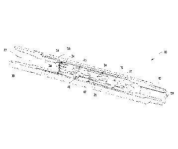
[0006] FIG. 1
is a perspective view of a downhole tool with a quarter
section removed and constructed in accordance with the present
disclosure.
[0007] FIG. 2
is a half cross-sectional view and half side elevation
view of the downhole tool constructed in accordance with the present
disclosure.
[0008] FIG. 3
is a partial cross-sectional view and perspective of the
downhole tool constructed in accordance with the present disclosure.
[0009] FIG. 4
is a cross-sectional view of the downhole tool
constructed in accordance with the present disclosure.
2

CA 02951397 2016-12-06
WO 2015/191889
PCT/US2015/035381
[0010] FIG. 5
is a cross-sectional view of the downhole tool turned
900 from the cross-sectional view shown in FIG. 4.
[0011] FIG. 6
is a perspective view of another embodiment of a
downhole tool with a quarter section removed and constructed in
accordance with the present disclosure.
[0012] FIG. 7
is a half cross-sectional view and half side elevation
view of the downhole tool shown in FIG. 6 and constructed in accordance
with the present disclosure.
DETAILED DESCRIPTION OF THE DISCLOSURE
[0013] The
present disclosure relates to a bypass tool 10 for running
down into a well as part of a bottom hole assembly (BHA). The bypass
tool 10 is used to divert the flow of fluid to a vibratory tool 12, which is
selectively in fluid communication with the bypass tool 10. The vibratory
tool 12 can be any tool known in the art for providing vibration and/or
agitation to a BHA to advance the BHA in the well, such as the Thru
Tubing Solutions, Inc.'s XRV, National Oilwell Varco's Agitator and Oil
State's Tempress tool.
[0014] The
fluid can flow around or through a portion of the vibratory
tool 12 and then be diverted to the vibratory tool 12 to operate the
vibratory tool 12. The vibratory tool 12 can be disposed within the
bypass tool 10, partially within the bypass tool 10 or positioned adjacent
to the bypass tool 10 on the downhole side of the bypass tool 10.
Generally, the vibratory tool 12 can include an, operational flow path 14
having an inlet 16 and an outlet 18. When fluid is permitted to flow into
3

CA 02951397 2016-12-06
WO 2015/191889
PCT/US2015/035381
the operational flow path 14, the vibratory tool 12 operates as intended.
It should be understood and appreciated that the vibratory tool 12 does
not have to be a completely separate tool. For example, the bypass tool
may include components that cause the bypass tool 10 to vibrate.
[0015]
Referring now to FIGS. 1-5, the bypass tool 10 includes a
housing 20, an inlet 22 for allowing fluid to flow into the bypass tool 10,
an outlet 24 for allowing fluid to flow out of the bypass tool 10, a bypass
passageway 26 disposed between the inlet 22 and outlet 24 for providing
an alternate flow path for fluid passing through the bypass tool 10, and a
screen 28 (or grate) to divert the flow of objects from the operational flow
path 14 of the vibratory tool 12. The bypass tool 10 also includes a top
adapter 30 for connecting the bypass tool 10 to a tool disposed above the
bypass tool 10 in the BHA and a bottom adapter 32 for connecting the
bypass tool 10 to other tools included in the BHA.
[0016] The
screen 28 is disposed downstream of the inlet 22 of the
bypass tool 10 and upstream of the vibratory tool 12 to block the flow of
objects to the operational flow path 14 of the vibratory tool 12 and permit
the flow of fluid to flow into the operational flow path 14 of the vibratory
tool 12 and the bypass passageway 26. The screen 28 can be sized and
shaped in any manner such that it prevents the flow of certain sized
objects from entering an annulus area 34 disposed adjacent to the inlet
16 of the operational flow path 14 of the vibratory tool 12. In one
embodiment, the screen 28 is a half cylinder shape to block the flow of
objects for half of an internal portion 36 of the bypass tool 10 upstream of
4

CA 02951397 2016-12-06
WO 2015/191889
PCT/US2015/035381
the vibratory tool 12. The screen 28 also acts to direct a fluid blocking
member 38 toward the bypass passageway 26 disposed in the bypass
tool 10.
[0017] In
another embodiment of the present disclosure, a second
screen 40 can be provided such that the second screen 40 is disposed at
the inlet 16 of the vibratory tool 12. The second screen 40 prevents the
fluid blocking member 38 from entering the operational flow path 14 of
the vibratory tool 12 and forces the fluid blocking member 38 into the
bypass passageway 26 wherein the fluid blocking member 38 will engage
a seat 42 (or shoulder) disposed in the bypass passageway 26 to prevent
the flow of fluid through the bypass passageway 26. When fluid is
blocked from flowing through the bypass passageway 26, the fluid is
forced to flow exclusively through the operational flow path 14 of the
vibratory tool 12 activating the vibratory tool 12 and causing it to
vibrate/agitate.
[0018] In use,
fluid is flowed into the inlet 22 of the bypass tool 10
and permitted to flow through the operational flow path 14 of the
vibratory tool 12 and the bypass passageway 26. When fluid is permitted
to flow through the operational flow path 14 and the bypass
passageway 26, the vibratory tool 12 is not generating a pressure drop,
thus there is no vibration or agitation occurring. When
vibration
characteristics are desired, the fluid blocking member 38 is pumped down
into the bypass tool 10. Due to the first and second screens 28 and 40,
the fluid blocking member 38 is directed toward the bypass

CA 02951397 2016-12-06
WO 2015/191889
PCT/US2015/035381
passageway 26 where the fluid blocking member 38 ultimately ends up
contacting the seat 42 disposed in the bypass passageway 26 to block the
flow of fluid through the bypass passageway 26. Once fluid is blocked
from flowing through the bypass passageway 26, all fluid is directed
toward the operational flow path 14 of the vibratory tool 12 which causes
the vibratory tool 12 to vibrate.
[0019] In yet
another embodiment of the present disclosure, shown
in FIGS. 6-7, the bottom hole assembly can include a second bypass
tool 50 to divert the flow of fluid to a second vibratory tool 52, which is
selectively in fluid communication with the second bypass tool 50. The
second vibratory tool 52 can be substantially the same as the first
vibratory tool 12. The fluid can flow around or through a portion of the
second vibratory tool 50 and then be diverted to the second vibratory
tool 52 to operate the second vibratory tool 52. The second vibratory
tool 52 can be disposed within the second bypass tool 50, partially within
the second bypass tool 50 or positioned adjacent to the second bypass
tool 52 on the downhole side of the second bypass tool 50. Generally, the
second vibratory tool 52 can include an operational flow path 54 having
an inlet 56 and an outlet 58. When fluid is permitted to flow into the
operational flow path 54 of the second vibratory tool 52, the second
vibratory tool 52 operates as intended. Similar to the first vibratory
tool 12, the second vibratory tool 52 does not have to be a completely
separate tool. For example, the second bypass tool 52 may include
components that cause the second bypass tool 52 to vibrate.
6

CA 02951397 2016-12-06
WO 2015/191889
PCT/US2015/035381
[0020] Similar
to the first bypass tool 10, the second bypass tool 50
includes a housing 60, an inlet 62 for allowing fluid to flow into the second
bypass tool 50, an outlet 64 for allowing fluid to flow out of the second
bypass tool 50, a bypass passageway 66 disposed between the inlet 62
and the outlet 64 of the second bypass tool 52 for providing an alternate
flow path for fluid passing through the second bypass tool 52, and a
screen 68 (or grate) to divert the flow of objects from the operational flow
path 54 of the second vibratory tool 52.
[0021] The
screen 68 is disposed downstream of the inlet 62 of the
second bypass tool 50 and upstream of the second vibratory tool 52 to
block the flow of objects to the operational flow path 54 of the second
vibratory tool 52 and permit the flow of fluid to flow to the operational
flow path 54 of the second vibratory tool 52 and the bypass
passageway 66 of the second bypass tool 50. The screen 68 can be sized
and shaped in any manner such that it prevents the flow of certain sized
objects from entering an annulus area 70 disposed adjacent to the
inlet 56 of the operational flow path 54 of the second vibratory tool 52.
In one embodiment, the screen 68 is a half cylinder shape to block the
flow of objects for half of the internal portion of the second bypass tool 50
upstream of the second vibratory tool 52. The screen 68 also acts to
direct a second fluid blocking member 72 toward the bypass passageway
66 in the second bypass tool 50.
[0022] In
another embodiment of the present disclosure, a second
screen 74 can be provided in the second bypass tool 50 such that the
7

CA 02951397 2016-12-06
WO 2015/191889
PCT/US2015/035381
second screen 74 is disposed at or near the inlet 56 of the second
vibratory tool 52. The second screen 74 of the second bypass tool 50
prevents the second fluid blocking member 72 from entering the
operational flow path 54 of the second vibratory tool 52 and forces the
second fluid blocking member 72 into the bypass passageway 66 of the
second bypass tool 50 wherein the second fluid blocking member 72 will
engage a seat 76 (or shoulder) disposed in the bypass passageway 66 of
the second bypass tool 50 to prevent the flow of fluid through the bypass
passageway 66. When fluid is blocked from flowing through the bypass
passageway 66 of the second bypass tool 50, the fluid is forced to flow
exclusively through the operational flow path 54 of the second vibratory
tool 52 activating the second vibratory tool 52, which would vibrate
and/or agitate the BHA.
[0023] It
should be understood that the second fluid blocking
member 72 is smaller than the first fluid blocking member 38, which
allows the second fluid blocking member 72 to flow through the bypass
passageway 26 disposed in the first bypass tool 10 and enter the second
bypass tool 50 and ultimately engage the seat 76 disposed in the bypass
passageway 66 of the second bypass tool 50. While not shown, it should
be understood and appreciated that there can be additional bypass tools
and vibratory tools implemented. For example, in the case of three
bypass tools, there would be a third fluid blocking member that was
smaller than the first and second fluid blocking members 38 and 72. This
would permit the third fluid blocking member to pass through the bypass
8

CA 02951397 2016-12-06
WO 2015/191889
PCT/US2015/035381
passageways 26 and 66 of the first and second bypass tools 10 and 50
and engage a seat disposed in a bypass passageway disposed in the third
bypass tool.
[0024] In use,
fluid is flowed into the inlet 22 of the first bypass
tool 10 and permitted to flow through the operational flow path 14 of the
first vibratory tool 12 and the bypass passageway 26 disposed in the first
bypass tool 10. The fluid is then permitted to flow from the outlet 24 of
the first bypass tool 10, into the inlet 62 of the second bypass tool 50 and
through the operational flow path 54 of the second vibratory tool 52 and
the bypass passageway 66 of the second bypass tool 50. When fluid is
permitted to flow through the operational flow paths 14 and 54 of the first
and second vibratory tools 12 and 52 and the bypass passageways 26
and 66 of the first and second bypass tools 10 and 50, the first and
second vibratory tools 12 and 52 are not generating a pressure drop, thus
there is no vibration occurring at either vibratory tool 12 or 52.
[0025] When
vibration characteristics are desired, the second fluid
blocking member 72 is pumped down into and through the first bypass
tool 10 (forced into and through the bypass passageway 26 of the first
bypass tool 10 via the first and second screens 28 and 40 of the first
bypass tool 10) and into the second bypass tool 50. Due to the first and
second screens 68 and 74 of the second bypass tool 50, the second fluid
blocking member 72 is directed toward the bypass passageway 66 of the
second bypass tool 50 where the second fluid blocking member 72
ultimately ends up contacting the seat 76 disposed in the bypass
9

CA 02951397 2016-12-06
WO 2015/191889
PCT/US2015/035381
passageway 66 of the second bypass tool 50 to block the flow of fluid
through the bypass passageway 66 of the second bypass tool 50. Once
fluid is blocked from flowing through the bypass passageway 66 of the
second bypass tool 50, all fluid is directed toward the operational flow
path 54 of the second vibratory tool 52 which causes the second vibratory
tool 52 to vibrate.
[0026] A
situation may be encountered where vibration of the first
vibratory tool 12 is desired in addition to the vibration of the second
vibratory tool 52, or after vibration of the first vibratory tool 12 has
ceased. In this situation, the first fluid blocking member 38 is pumped
down into the first bypass tool 10. Due to the first and second screens 28
and 40 of the first bypass tool 10, the first fluid blocking member 38 is
directed toward the bypass passageway 26 of the first bypass tool 10
where the first fluid blocking member 38 ultimately ends up contacting
the seat 42 disposed in the bypass passageway 26 of the first bypass
tool 10 to block the flow of fluid through the bypass passageway 26 of the
first bypass tool 10. Once fluid is blocked from flowing through the
bypass passageway 26 of the first bypass tool 10, all fluid is directed
toward the operational flow path 14 of the first vibratory tool 12, which
causes the first vibratory tool 12 to vibrate.
[0027] The
present disclosure is also directed to a method of using
the downhole bypass tool. The BHA can be run down into a wellbore.
Fluid can be flowed into and through the BHA to perform a variety of
downhole oil and gas operations. A vibratory operation can then be

CA 02951397 2016-12-06
WO 2015/191889
PCT/US2015/035381
initiated in the wellbore. The vibratory operation can be stopped and the
oil and gas operations can then be continued. A second vibratory
operation can be initiated in the wellbore. Similar to the first vibratory
operation, the second vibratory operation can be stopped and the oil and
gas operations can again be continued.
[0028] From the
above description, it is clear that the present
disclosure is well adapted to carry out the objectives and to attain the
advantages mentioned herein as well as those inherent in the disclosure.
While presently preferred embodiments have been described herein, it will
be understood that numerous changes may be made which will readily
suggest themselves to those skilled in the art and which are accomplished
within the spirit of the disclosure and claims.
11

Representative Drawing
A single figure which represents the drawing illustrating the invention.
Administrative Status

2024-08-01:As part of the Next Generation Patents (NGP) transition, the Canadian Patents Database (CPD) now contains a more detailed Event History, which replicates the Event Log of our new back-office solution.

Please note that "Inactive:" events refers to events no longer in use in our new back-office solution.

For a clearer understanding of the status of the application/patent presented on this page, the site Disclaimer , as well as the definitions for Patent , Event History , Maintenance Fee  and Payment History  should be consulted.

Event History

Description Date
Letter Sent 2022-12-05
Refund Request Received 2022-11-09
Inactive: Reply received: MF + late fee 2022-10-31
Inactive: Correspondence - MF 2022-09-16
Inactive: Correspondence - MF 2022-09-08
Inactive: Office letter 2022-08-10
Inactive: Reply received: MF + late fee 2022-07-11
Grant by Issuance 2022-06-28
Inactive: Grant downloaded 2022-06-28
Letter Sent 2022-06-28
Inactive: Cover page published 2022-06-27
Pre-grant 2022-04-07
Inactive: Final fee received 2022-04-07
Notice of Allowance is Issued 2022-01-06
Letter Sent 2022-01-06
Notice of Allowance is Issued 2022-01-06
Inactive: Approved for allowance (AFA) 2021-11-09
Inactive: Q2 passed 2021-11-09
Amendment Received - Voluntary Amendment 2021-09-29
Amendment Received - Response to Examiner's Requisition 2021-09-29
Maintenance Fee Payment Determined Compliant 2021-06-25
Examiner's Report 2021-06-23
Inactive: Report - No QC 2021-06-15
Common Representative Appointed 2020-11-07
Letter Sent 2020-06-23
Inactive: COVID 19 - Deadline extended 2020-06-10
Request for Examination Received 2020-06-02
Request for Examination Requirements Determined Compliant 2020-06-02
All Requirements for Examination Determined Compliant 2020-06-02
Inactive: COVID 19 - Deadline extended 2020-05-28
Change of Address or Method of Correspondence Request Received 2020-05-08
Common Representative Appointed 2019-10-30
Inactive: Cover page published 2017-01-05
Inactive: Notice - National entry - No RFE 2016-12-19
Inactive: First IPC assigned 2016-12-15
Inactive: IPC assigned 2016-12-15
Application Received - PCT 2016-12-15
National Entry Requirements Determined Compliant 2016-12-06
Letter Sent 2016-12-06
Application Published (Open to Public Inspection) 2015-12-17

Abandonment History

There is no abandonment history.

Maintenance Fee

The last payment was received on 2022-10-31

Note : If the full payment has not been received on or before the date indicated, a further fee may be required which may be one of the following

  • the reinstatement fee;
  • the late payment fee; or
  • additional fee to reverse deemed expiry.

Please refer to the CIPO Patent Fees web page to see all current fee amounts.

Fee History

Fee Type Anniversary Year Due Date Paid Date
Basic national fee - standard 2016-12-06
Registration of a document 2016-12-06
MF (application, 2nd anniv.) - standard 02 2017-06-12 2016-12-06
MF (application, 3rd anniv.) - standard 03 2018-06-11 2018-05-17
MF (application, 4th anniv.) - standard 04 2019-06-11 2019-04-29
Request for examination - standard 2020-07-06 2020-06-02
MF (application, 5th anniv.) - standard 05 2020-06-11 2020-06-02
MF (application, 6th anniv.) - standard 06 2021-06-11 2021-06-25
Late fee (ss. 27.1(2) of the Act) 2021-06-25 2021-06-25
Final fee - standard 2022-05-06 2022-04-07
MF (application, 7th anniv.) - standard 07 2023-06-12 2022-10-31
MF (patent, 8th anniv.) - standard 2023-06-12 2022-10-31
Late fee (ss. 46(2) of the Act) 2023-06-12 2022-10-31
MF (patent, 9th anniv.) - standard 2024-06-11 2024-06-07
Owners on Record

Note: Records showing the ownership history in alphabetical order.

Current Owners on Record
THRU TUBING SOLUTIONS, INC.
Past Owners on Record
ANDY FERGUSON
ROGER SCHULTZ
Past Owners that do not appear in the "Owners on Record" listing will appear in other documentation within the application.
Documents

To view selected files, please enter reCAPTCHA code :


To view images, click a link in the Document Description column. To download the documents, select one or more checkboxes in the first column and then click the "Download Selected in PDF format (Zip Archive)" or the "Download Selected as Single PDF" button.

List of published and non-published patent-specific documents on the CPD .

If you have any difficulty accessing content, you can call the Client Service Centre at 1-866-997-1936 or send them an e-mail at CIPO Client Service Centre.


Document
Description 
Date
(yyyy-mm-dd) 
Number of pages   Size of Image (KB) 
Representative drawing 2022-06-06 1 14
Description 2016-12-06 11 413
Representative drawing 2016-12-06 1 27
Claims 2016-12-06 6 184
Drawings 2016-12-06 4 133
Abstract 2016-12-06 1 74
Cover Page 2017-01-05 1 59
Claims 2021-09-29 5 178
Cover Page 2022-06-06 1 52
Maintenance fee payment 2024-06-07 7 268
Notice of National Entry 2016-12-19 1 193
Courtesy - Certificate of registration (related document(s)) 2016-12-06 1 103
Courtesy - Acknowledgement of Request for Examination 2020-06-23 1 433
Courtesy - Acknowledgement of Payment of Maintenance Fee and Late Fee 2021-06-25 1 433
Commissioner's Notice - Application Found Allowable 2022-01-06 1 570
National entry request 2016-12-06 10 288
International search report 2016-12-06 2 91
Maintenance fee payment 2018-05-17 1 26
Maintenance fee payment 2019-04-29 1 26
Maintenance fee payment 2020-06-02 1 27
Request for examination 2020-06-02 3 123
Examiner requisition 2021-06-23 3 153
Amendment / response to report 2021-09-29 18 820
Final fee 2022-04-07 5 134
Electronic Grant Certificate 2022-06-28 1 2,527
Maintenance fee + late fee 2022-07-11 2 42
Courtesy - Office Letter 2022-08-10 2 196
Maintenance fee correspondence 2022-09-08 1 28
Maintenance fee correspondence 2022-09-16 1 30
Maintenance fee + late fee 2022-10-31 2 45
Refund 2022-11-09 1 42
Courtesy - Acknowledgment of Refund 2022-12-05 1 166