Language selection

Search

Patent 2952668 Summary

Third-party information liability

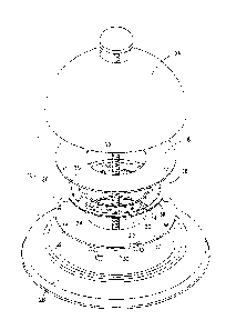
Some of the information on this Web page has been provided by external sources. The Government of Canada is not responsible for the accuracy, reliability or currency of the information supplied by external sources. Users wishing to rely upon this information should consult directly with the source of the information. Content provided by external sources is not subject to official languages, privacy and accessibility requirements.

Claims and Abstract availability

Any discrepancies in the text and image of the Claims and Abstract are due to differing posting times. Text of the Claims and Abstract are posted:

  • At the time the application is open to public inspection;
  • At the time of issue of the patent (grant).
(12) Patent Application: (11) CA 2952668
(54) English Title: SOLID STATE LIGHT ASSEMBLY FOR FLUSH MOUNTED LED LIGHTING FIXTURES
(54) French Title: ENSEMBLE D'ECLAIRAGE A SEMI-CONDUCTEURS POUR LUMINAIRES A DEL MONTES DE MANIERE AFFLEURANTE
Status: Examination
Bibliographic Data
(51) International Patent Classification (IPC):
  • F21K 9/00 (2016.01)
  • F21K 9/237 (2016.01)
  • F21S 8/04 (2006.01)
(72) Inventors :
  • TREADWAY, PATRICK (United States of America)
(73) Owners :
  • MAXLITE, INC.
(71) Applicants :
  • MAXLITE, INC. (United States of America)
(74) Agent: PIASETZKI NENNIGER KVAS LLP
(74) Associate agent:
(45) Issued:
(22) Filed Date: 2016-12-28
(41) Open to Public Inspection: 2017-06-30
Examination requested: 2021-11-22
Availability of licence: N/A
Dedicated to the Public: N/A
(25) Language of filing: English

Patent Cooperation Treaty (PCT): No

(30) Application Priority Data:
Application No. Country/Territory Date
62/273,025 (United States of America) 2015-12-30
62/287,144 (United States of America) 2016-01-26

Abstracts

English Abstract


An assembly is provided herein for a lighting fixture and for retrofitting a
flush mounted
light fixture to be provided with solid state lighting.


Claims

Note: Claims are shown in the official language in which they were submitted.

CLAIMS
What is claimed is:
1. A lighting fixture comprising:
a lighting unit including a plurality of light generating diodes and a driver
configured to
convert incoming alternating current power to direct current power for said
plurality of light
generating diodes;
a barrier sized and shaped to limit contact with said lighting unit, wherein
said barrier is
sufficiently light transmissive to permit light generated by said lighting
unit to pass therethrough;
and,
a plurality of stand offs mountingly supporting said barrier relative to said
lighting unit in
a spaced-apart relationship.
2. The lighting fixture of claim 1, wherein said barrier is made of glass.
3. The lighting fixture of claim 1, wherein said barrier is made of a
material which satisfies
UL 94 5VA flammability rating.
4. The lighting fixture of claim 1, further comprising a carrier,
5. The lighting fixture of claim 4, wherein said carrier is metallic.

6. The lighting fixture of claim 4, wherein said stand offs are fixed to
said barrier and to
said carrier.
7. The lighting fixture of claim 4, further comprising a thermal pad
located between said
lighting unit and said carrier.
8. The lighting fixture of claim 7, wherein said lighting unit is fixed to
said carrier.
9. The lighting fixture of claim 4, further comprising a thermal barrier
located between said
lighting unit and said carrier, said thermal barrier configured to conduct
heat from said lighting
unit to said carrier.
10. The lighting fixture of claim 9, wherein said lighting unit is fixed to
said carrier.
11. The lighting fixture of claim 1, wherein said stand offs are fixed to
said barrier and said
lighting unit.
12. The lighting fixture of claim 1, wherein said barrier includes a
central opening to allow
passage therethrough of mounting hardware for the lighting fixture.
13. The lighting fixture of claim 1, wherein said barrier at least overlaps
the light generating
diodes.
6

14. A retrofit assembly for flush mounted light fixtures, the assembly
comprising:
a lighting unit including a plurality of light generating diodes and a driver
configured to
convert incoming alternating current power to direct current power for said
plurality of light
generating diodes;
a barrier sized and shaped to limit contact with said lighting unit, wherein
said barrier is
sufficiently light transmissive to permit light generated by said lighting
unit to pass therethrough;
and,
a plurality of stand offs mountingly supporting said barrier relative to said
lighting unit in
a spaced-apart relationship.
15. The lighting fixture of claim 14, wherein said barrier is made of
glass.
16. The lighting fixture of claim 14, wherein said barrier is made of a
material which satisfies
UL 94 5VA flammability rating.
17. The lighting fixture of claim 14, further comprising a carrier.
18. The lighting fixture of claim 17, wherein said carrier is metallic.
19. The lighting fixture of claim 17, wherein said stand offs are fixed to
said barrier and to
said carrier.
7

20. The lighting fixture of claim 17, further comprising a thermal pad
located between said
lighting unit and said carrier.
21. The lighting fixture of claim 20, wherein said lighting unit is fixed
to said carrier.
22. The lighting fixture of claim 17, further comprising a thermal barrier
located between
said lighting unit and said carrier, said thermal barrier configured to
conduct heat from said
lighting unit to said carrier.
23. The lighting fixture of claim 22, wherein said lighting unit is fixed
to said carrier.
24. The lighting fixture of claim 14, wherein said stand offs are fixed to
said barrier and said
lighting unit.
25. The lighting fixture of claim 14, wherein said barrier includes a
central opening to allow
passage therethrough of mounting hardware for the lighting fixture.
26. The lighting fixture of claim 14, wherein said barrier at least
overlaps the light generating
diodes.
8

Description

Note: Descriptions are shown in the official language in which they were submitted.


CA 02952668 2016-12-28
SOLID STATE LIGHT ASSEMBLY
FOR FLUSH MOUNTED LIGHTING FIXTURES
BACKGROUND OF THE INVENTION
[0001] Flush mounted lighting fixtures, which are typically ceiling
mounted, are well
known in the prior art. These lighting fixtures are typically provided with
E26 sockets, or the
like, for incandescent bulbs, or GU24 sockets, or the like, for compact
fluorescent bulbs.
[0002] Solid state lighting, such as provided by light emitting diodes
(LED's), organic
light emitting diodes (OLED's), or polymer light emitting diodes (PLED's), has
been found to be
more energy efficient than incandescent or fluorescent lighting. Thus, there
has been a
movement to utilize solid state lighting over incandescent or fluorescent
lighting. Light fixtures
configured for incandescent or fluorescent lighting must be retrofitted to
accommodate solid
state lighting, if there is a desire to retain the light fixtures for use with
solid state lighting.
SUMMARY OF THE INVENTION
[0003] An assembly is provided herein for a lighting fixture and for
retrofitting a flush
mounted light fixture to be provided with solid state lighting.
BRIEF DESCRIPTION OF THE DRAWINGS
[0004] Figure 1 is an exploded view of a lighting fixture in
accordance with the subject
invention;
[0005] Figure 2 is an exploded view of a lighting fixture in
accordance with the subject
invention, and;
1

I[
CA 02952668 2016-12-28
[0006] Figure 3 is an exploded view of an assembly in accordance with
the subject
invention.
DETAILED DESCRIPTION OF THE INVENTION
[0007] With reference to the attached Figures, an assembly 10 may be
provided which
includes a carrier 12, a lighting unit 14, stand offs 16 and a protective
barrier 18. Preferably, the
carrier 12 is formed of metal, such as sheet metal or aluminum, and is sized
to accommodate the
lighting unit 14. The carrier 12 preferably has thermal conductive properties
to dissipate heat
generated by the lighting unit 14. The lighting unit 14 preferably includes a
printed circuit board
20 to which one or more light elements 22, which may be in the form of light
generating diodes,
such as LED's, OLED's, and/or PLED's, are electronically coupled to a driver
24. The driver 24
is configured to convert incoming alternating current power to direct current
power for the light
elements 22. Additional features may be included with the lighting unit 14,
including a dimmer,
detection sensors (e.g., motion detection) and/or a bluetooth or other
wireless receiver for
receiving control commands from a remote source. The lighting unit 14 may be
mounted or
affixed to the carrier 12 in any known manner.
[0008] The stand offs 16 are mounted or affixed, on one hand, to the
lighting unit 14
and/or the carrier 12, and, on the other hand, to the barrier 18, preferably
defining a space 26
therebetween. It is preferred that the stand offs 16 be mounted permanently to
the lighting unit
14 and the barrier 18, such as by gluing, fusing, riveting and the like, so
that the barrier 18 may
be only removed from the stand offs 16 through destructive means. The stand
offs 16 may be of
various materials which are stable in relatively warm environments, including
being of
polymeric material(s), e.g., nylon, and/or metal.
2

I[
CA 02952668 2016-12-28
[0009] The barrier 18 may be of glass or other materials (e.g.,
polymeric materials)
which satisfy UL 94 5VA flammability rating. It is also preferred that the
barrier 18 be
sufficiently light transmissive to permit light generated by the lighting unit
14 to pass
therethrough. The barrier 18 is sized and shaped to limit contact with the
lighting unit 14,
particularly where high voltage sources, the light elements 22 and other
components are
mounted, by a user. Preferably, the barrier has an outer footprint at least as
great as the light
elements 22 of the lighting unit 14 ¨ i.e., the outer footprint of the barrier
18 causes the barrier
18 to at least overlap completely the area of the light elements 22 of the
lighting unit 14. The
barrier 18 preferably overlaps the lighting unit 14 at a minimum and may be
formed with a
greater footprint from the lighting unit 14.
[0010] The assembly 10 is preferably provided as a pre-assembled kit
which is ready for
mounting. The assembly 10 may be formed in different shapes, including being
annular to allow
for mounting into a round flush mounted light fixture pan 28 with a center
space 30 permitting
mounting hardware 32 for a corresponding diffuser 34. Other shapes are
possible.
[0011] Optionally, a thermal pad or other conductive barrier (e.g., a layer
of grease) 36
(Figure 1) may be provided with the assembly 10, for example between the
lighting unit 14 and
the carrier 12. The thermal pad or conductive barrier 36 further acts to
conduct heat form the
lighting unit 14 to the carrier 12.
[0012] It is possible to provide the assembly 10 in pre-assembled sub-
elements, such as
the barrier 18, the stand offs 16 and the lighting element 14 being provided
unitarily with
separate assembly of the carrier 12 and the thermal pad or other conductive
barrier 36 if
provided.
3

I[
CA 02952668 2016-12-28
[0013] For retrofit, an existing socket or sockets is removed from the
pan 28 or other
base element of an existing light fixture such as a flush mounted light
fixture (which may be
ceiling mounted). The assembly 10 described herein may be secured to the pan
28 or base
element using screws or other known fasteners. The power supply wires which
were used to
provide standard alternating current power (e.g., 110/120 VAC or 220/240 VAC)
to the
socket(s), and are now disconnected, are connected to the driver 24 to provide
power thereto.
The carrier 12 may be ground to the base or pan 28 as well if necessary. The
power supply wires
may be pulled through an opening of the assembly 10 for possible easier
connection to the driver
24. With the alternating current power supply electrically coupled to the
driver 24, the lighting
unit 14 is fully powered to provide light.
[0014] As an alternative, the assembly 10 of the lighting unit 14, the
stand offs 16 and the
barrier 18 may be provided with a flush mounted light fixture, sold as a new
product. Here, the
assembly 10 is provided as the light source with no retrofitting required. The
carrier 12 and/or
the thermal pad or other-conductive barrier 36 may be optionally utilized.
4

Representative Drawing
A single figure which represents the drawing illustrating the invention.
Administrative Status

2024-08-01:As part of the Next Generation Patents (NGP) transition, the Canadian Patents Database (CPD) now contains a more detailed Event History, which replicates the Event Log of our new back-office solution.

Please note that "Inactive:" events refers to events no longer in use in our new back-office solution.

For a clearer understanding of the status of the application/patent presented on this page, the site Disclaimer , as well as the definitions for Patent , Event History , Maintenance Fee  and Payment History  should be consulted.

Event History

Description Date
Examiner's Report 2024-08-15
Amendment Received - Response to Examiner's Requisition 2024-02-14
Change of Address or Method of Correspondence Request Received 2024-02-14
Amendment Received - Voluntary Amendment 2024-02-14
Examiner's Report 2023-10-16
Inactive: Office letter 2023-10-05
Withdraw Examiner's Report Request Received 2023-10-05
Inactive: Report - No QC 2023-10-03
Inactive: Office letter 2023-09-29
Inactive: Delete abandonment 2023-09-29
Inactive: Adhoc Request Documented 2023-09-29
Inactive: Correspondence - Prosecution 2023-09-14
Deemed Abandoned - Failure to Respond to an Examiner's Requisition 2023-05-24
Examiner's Report 2023-01-24
Inactive: Report - No QC 2022-12-22
Letter Sent 2021-12-06
Request for Examination Requirements Determined Compliant 2021-11-22
Request for Examination Received 2021-11-22
All Requirements for Examination Determined Compliant 2021-11-22
Common Representative Appointed 2020-11-07
Common Representative Appointed 2019-10-30
Application Published (Open to Public Inspection) 2017-06-30
Inactive: Cover page published 2017-06-29
Inactive: IPC assigned 2017-01-09
Inactive: First IPC assigned 2017-01-09
Inactive: IPC assigned 2017-01-09
Filing Requirements Determined Compliant 2017-01-03
Inactive: Filing certificate - No RFE (bilingual) 2017-01-03
Letter Sent 2016-12-30
Application Received - Regular National 2016-12-30

Abandonment History

Abandonment Date Reason Reinstatement Date
2023-05-24

Maintenance Fee

The last payment was received on 2023-12-04

Note : If the full payment has not been received on or before the date indicated, a further fee may be required which may be one of the following

  • the reinstatement fee;
  • the late payment fee; or
  • additional fee to reverse deemed expiry.

Please refer to the CIPO Patent Fees web page to see all current fee amounts.

Fee History

Fee Type Anniversary Year Due Date Paid Date
Registration of a document 2016-12-28
Application fee - standard 2016-12-28
MF (application, 2nd anniv.) - standard 02 2018-12-28 2018-11-06
MF (application, 3rd anniv.) - standard 03 2019-12-30 2019-11-28
MF (application, 4th anniv.) - standard 04 2020-12-29 2020-11-25
Request for examination - standard 2021-12-29 2021-11-22
MF (application, 5th anniv.) - standard 05 2021-12-29 2021-11-22
MF (application, 6th anniv.) - standard 06 2022-12-28 2022-12-01
MF (application, 7th anniv.) - standard 07 2023-12-28 2023-12-04
Owners on Record

Note: Records showing the ownership history in alphabetical order.

Current Owners on Record
MAXLITE, INC.
Past Owners on Record
PATRICK TREADWAY
Past Owners that do not appear in the "Owners on Record" listing will appear in other documentation within the application.
Documents

To view selected files, please enter reCAPTCHA code :


To view images, click a link in the Document Description column. To download the documents, select one or more checkboxes in the first column and then click the "Download Selected in PDF format (Zip Archive)" or the "Download Selected as Single PDF" button.

List of published and non-published patent-specific documents on the CPD .

If you have any difficulty accessing content, you can call the Client Service Centre at 1-866-997-1936 or send them an e-mail at CIPO Client Service Centre.


Document
Description 
Date
(yyyy-mm-dd) 
Number of pages   Size of Image (KB) 
Claims 2024-02-14 6 342
Description 2016-12-28 4 133
Abstract 2016-12-28 1 4
Claims 2016-12-28 4 87
Drawings 2016-12-28 3 111
Representative drawing 2017-06-07 1 12
Cover Page 2017-06-07 1 37
Examiner requisition 2024-08-15 4 117
Amendment / response to report 2024-02-14 23 729
Change to the Method of Correspondence 2024-02-14 4 79
Filing Certificate 2017-01-03 1 203
Courtesy - Certificate of registration (related document(s)) 2016-12-30 1 102
Reminder of maintenance fee due 2018-08-29 1 111
Courtesy - Acknowledgement of Request for Examination 2021-12-06 1 434
Prosecution correspondence 2023-09-14 12 459
Change to the Method of Correspondence 2023-09-14 12 459
Courtesy - Office Letter 2023-09-29 1 195
Courtesy - Office Letter 2023-10-05 1 158
Examiner requisition 2023-10-16 5 216
Maintenance fee payment 2023-12-04 1 26
Maintenance fee payment 2018-11-06 1 25
New application 2016-12-28 14 1,682
Maintenance fee payment 2019-11-28 1 26
Maintenance fee payment 2020-11-25 1 26
Maintenance fee payment 2021-11-22 1 26
Request for examination 2021-11-22 3 100
Maintenance fee payment 2022-12-01 1 26
Examiner requisition 2023-01-24 5 216