Note: Descriptions are shown in the official language in which they were submitted.
CA 02952671 2016-12-15
TITLE OF THE INVENTION
POWER OVER ETHERNET EMERGENCY LIGHTING SYSTEM AND METHOD OF
DETECTING POWER LOSS OF A LINK SEGMENT THEREOF
CROSS REFERENCE TO RELATED APPLICATIONS
[0001] This application claims the benefit of U.S. Provisional Patent
Application No.
62/135,006 filed on March 18, 2015, titled "POWER OVER ETHERNET EMERGENCY
LIGHTING SYSTEM."
BACKGROUND OF THE INVENTION
TECHNICAL FIELD
[0002] The present invention relates to emergency lighting systems, and
more
particularly to providing emergency lighting systems powered by power over
Ethernet ("POE")
systems.
BACKGROUND ART
[0003] Lighting systems, particularly in commercial settings, are subject
to a number of
strict functional requirements set by various standard setting organizations.
Among these is the
requirement that emergency lighting be provided in the event of a loss of
building power. These
mandated emergency power systems must provide backup lighting for a
predetermined period of
time, must be tamper, fire, flood and earthquake resistant, and must meet
certain other functional
requirements. Conventionally, emergency lighting systems are provided as self-
contained units
installed in light fixtures, which include batteries charged by a dedicated
A/C power line.
[0004] The promulgation of IEEE standards for power-over-Ethernet ("POE"),
combined with the ubiquity of RJ45 Ethernet cabling in modern business and
residential
buildings, provides alternative means for building lighting. There are at
present two ratified
IEEE standards for POE: IEEE 802.3af and IEEE 802.3at. An Ethernet port
operating in
accordance with the IEEE 802.3af standard is capable of supplying 12.95 Watts
to powered
devices ("PDs") over a POE link. IEEE 802.3at defines the POE+ standard, which
enables the
delivery of up to 25.5W over a POE link. Current efforts are underway to
promulgate more
advanced POE standards (e.g., POE+ and POE-HO, which will specify equipment
capable of
supplying up to 90W over a POE link.
[0005] Realizing a POE link over the physical connections of Cat5+ Ethernet
cable is
done according to one of two alternatives, illustrated schematically in FIG. 1
As can be seen in
FIG. I, an RJ45 Ethernet cable 105 carries 8 conductors grouped as 4 twisted
pairs (110a,b and
1
CA 02952671 2016-12-15
WO 2016/149549 PCT/US2016/022964
115a,b), with two twisted pairs (e.g., 110, 115) forming a communication link
for a first port
(transmit and receive), and with the two remaining twisted pairs available as
spares (e.g.,
115a,b). In Alternative A, a DC voltage is supplied over data lines, across
center taps on internal
signal coupling transformers (120 a,b) connected across the pair of conductors
on each of the
transmit and receive twisted pairs. The DC voltage is then supplied from the
center taps of
another pair of transformers (125 a,b) across the receive-side twisted pairs
for the transmit and
receive lines. This DC voltage is supplied to a powered device 130 on the
receive end of the
link. In Alternative B of the POE standard, DC voltage is supplied through the
unused or spare
twisted pairs. Newer and proposed POE standards provide more power and faster
data using all
8 conductors. These methods require 4 Data transformers, where Power is
imposed on all pairs.
[0006] In recent years, with the declining cost and increased efficiency
of light emitting
diodes ("LEDs"), LED lighting has begun to replace fluorescent lighting in
commercial settings.
FIG. 2 is a schematic representation of a conventional LED lighting
installation powered by a
POE link, or more precisely, an Ethernet cable referred to under the POE
standards as a Port
Data Link Segment. 48V DC nominal is supplied over the link by power sourcing
equipment
("PSE") 205 (e.g., a POE switch, hub or midspan injector). The power is
superimposed on data
transmission wire pairs of an Ethernet link segment (e.g., 210a, b) carried on
a CATnx (e.g., Cat
5+) cable. The link segments (210a,b) supply power to a Powered Device (PD),
for example,
POE luminaire Lighting LED Driver 220, where the power is intelligently
extracted (i.e.,
separated from the data) at the PD. Power extraction occurs at a POE Lighting
LED Driver 220,
which appears to the PSE as any conventional PSE operating according to the
POE standards.
Power is then delivered by the driver 220 to LED lamps 225. In certain
conventional
implementations, driver 220 and LED lamps 225 are co-located in an LED
luminaire 215, which
is installed, for example at a ceiling light fixture.
[0007] In a typical AC Power System, certain luminaires (i.e., light
fixtures) are
designated as also emergency luminaires, which by code and accepted building
practice must
maintain illumination upon a loss of AC power. Luminaires are complete with
all the necessary
luminaire components; e.g., light sources (lamps, such as LEDs), a ballast or
lamp power supply
such as an LED driver), etc. If a luminaire is to also act as an emergency
luminaire, it is
outfitted with additional hardware enabling it to drive all or a portion of
the light sources (i.e.,
lamps) for emergency illumination in emergency-mode operation - a condition
triggered by the
loss AC power. Thus, the existing lamps in these luminaires are used both for
normal lighting
when AC power is supplied, and also for illumination in emergency-mode
operation when
normal AC power fails.
2
CA 02952671 2016-12-15
WO 2016/149549 PCT/US2016/022964
SUMMARY OF THE INVENTION
[0008] The invention is directed to an emergency lighting luminaire
powered by a POE
network connection deployed, for example, in the context of existing POE
lighting.
Embodiments of the invention include a first power enabled Ethernet link
segment, a
rechargeable emergency battery pack, a normal lighting LED driver, an LED
lamp, and a power
loss monitor. In certain embodiments, the first power enabled Ethernet
connects to a POE port
link segment. Further, the rechargeable emergency battery pack contains a
battery charger, a
rechargeable battery, and an emergency LED driver, which is connected to one
input of a
relaying device. Moreover, the other input of the relaying device is
electrically connected to a
normal lighting LED driver, which drives an LED lighting array under normal
operating
conditions and the output of the relaying device is connected to the LED lamp.
[0009] Embodiments of the invention further include a power loss monitor,
which
determines whether power is being provided over the normal lighting LED driver
or whether
there has been an interruption of power. When the power loss monitor detects a
loss of power
from the normal lighting LED driver, a controller, which is connected to the
power loss monitor,
connects one input of the relaying device to the LED lamp. However, when the
normal LED
driver has power, the other input of the relaying device is connected to the
LED lamp.
[0010] In certain embodiments, the emergency lighting luminaire further
comprises a
second POE input connectable to a power POE port link segment. When the first
POE input is
connected to the battery charger, the second POE input is connected to the
normal lighting LED
driver. Further, the first and second POE inputs are included in the emergency
battery pack,
which further includes a POE output that is connected to the second POE input
by a pass-
through loop. The POE output is also connected to the normal lighting LED
driver. In other
embodiments, the power loss monitor communicates with the normal lighting POE
link pass-
through loop.
[0011] In certain embodiments, the relaying device, adapted to form an
electrical
connection between the battery and the LED lighting array (or a stand-alone
emergency LED
array), is an electro-mechanical switch. In other embodiments, the relaying
device is a solid-
state device.
[0012] In certain embodiments, the POE emergency luminaire including the
battery
charged by a port link segment that is entirely independent from the port link
segment driving
normal lighting. In other embodiments, the system includes a battery charged
with DC power
via an auxiliary power output interface from the normal lighting LED driver,
which itself is
3
CA 02952671 2016-12-15
WO 2016/149549 PCT/US2016/022964
driven by a single POE port link segment. In other embodiments, the single POE
port link
segment supplies power to an emergency backup battery pack, which then
supplies normal
lighting power via a power bridge.
[0013] In certain embodiments, the power loss monitor is connected to a
first conductor
on a first POE data pair of a POE port link segment, and the power loss
monitor is connected to
a second conductor on a second data pair of the same POE port link segment.
The power loss
monitor capable of determining when a POE port link segment loses power, but
without
interfering with data communications on that link segment. In other
embodiments, the power
loss monitor further includes an opto-coupler, a resistor, and a Zener diode.
The power loss
monitor regulates current flowing through the LED of the opto-coupler based on
whether the
voltage differential between the first and second conductors exceeds a
predetermined threshold.
Further, the power loss monitor includes ferrite beads capable of filtering
connected between the
rectifying diode bridge and the first and second conductors. Moreover, the
first and second
conductors are connected to POE link segment over the first power over
Ethernet input.
[0014] Embodiments of the invention also provides a system for providing
emergency
backup power in a POE luminaire, which has a connection to a POE link segment,
a lamp driver
and a lamp. The system further contains a power loss monitor connected to
detect a loss of POE
power in the POE link segment and an emergency backup battery and lamp driver
connected to
supply power to the lamp when the power loss monitor detects a loss of POE
power in the POE
link segment.
[0015] Moreover, embodiments of the invention provides a method of
detecting power
loss in a POE link segment, comprising the steps of detecting a differential
DC voltage between
a first conductor in a first data pair on a POE link segment and a second
conductor in a second
data pair on the same POE link segment. In certain embodiments, the step of
detecting the
differential DC voltage includes detecting a decrease in current through a
measurement device
when the differential DC voltage between a first conductor in a first data
pair on a POE link
segment and a second conductor in a second data pair on the same POE link
segment drops
below a predetermined threshold.
BRIEF DESCRIPTION OF THE DRAWINGS
[0016] The invention will be more fully understood by referring to the
following
Detailed Description of Specific Embodiments in conjunction with the Drawings,
which are
embedded in the Detailed Description below.
[0017] Fig. 1 is a schematic illustration of a conventional Power-over-
Ethernet link.
4
CA 02952671 2016-12-15
WO 2016/149549 PCT/US2016/022964
[0018] Fig. 2 is a schematic illustration of a conventional LED-based POE
lighting
system.
[0019] Fig. 3 is a schematic illustration of a POE emergency lighting
luminaire having
two POE port links according to an embodiment of the invention.
[0020] Fig. 4 is a schematic illustration of an emergency POE battery
pack for use with
the luminaire of Fig. 3.
[0021] Fig. 5 is a schematic illustration of a POE emergency lighting
luminaire using an
auxiliary power link according to an embodiment of the invention.
[0022] Fig 6 is a schematic illustration of an emergency POE battery pack
for use with
the luminaire of Fig. 5.
[0023] Fig. 7 is a schematic illustration of a POE emergency lighting
luminaire using a
port power bridge according to an embodiment of the invention.
[0024] Fig. 8 is a schematic illustration of an emergency POE battery
pack for use with
the luminaire of Fig. 7.
[0025] Fig. 9 is a schematic diagram of a POE interface according to the
invention.
[0026] Fig. 10 is a circuit diagram of a power loss monitor according to
an embodiment
of the invention.
DETAILED DESCRIPTION OF SPECIFIC EMBODIMENTS
[0027] A detailed description of preferred embodiments of the invention
is set forth
below.
[0028] References throughout this specification to "one embodiment," "an
embodiment," "a related embodiment," or similar language mean that a
particular feature,
structure, or characteristic described in connection with the referred to
"embodiment" is included
in at least one embodiment of the present invention. Thus, appearances of the
phrases "in one
embodiment," "in an embodiment," and similar language throughout this
specification may, but
do not necessarily, all refer to the same embodiment. It is to be understood
that no portion of
disclosure, taken on its own and in possible connection with a figure, is
intended to provide a
complete description of all features of the invention.
[0029] In addition, the following disclosure may describe features of the
invention with
reference to corresponding drawings, in which like numbers represent the same
or similar
elements wherever possible. In the drawings, the depicted structural elements
are generally not
to scale, and certain components are enlarged relative to the other components
for purposes of
emphasis and understanding. It is to be understood that no single drawing is
intended to support
CA 02952671 2016-12-15
WO 2016/149549 PCT/US2016/022964
a complete description of all features of the invention. In other words, a
given drawing is
generally descriptive of only some, and generally not all, features of the
invention. A given
drawing and an associated portion of the disclosure containing a description
referencing such
drawing do not, generally, contain all elements of a particular view or all
features that can be
presented is this view, for purposes of simplifying the given drawing and
discussion, and to
direct the discussion to particular elements that are featured in this
drawing. A skilled artisan
will recognize that the invention may possibly be practiced without one or
more of the specific
features, elements, components, structures, details, or characteristics, or
with the use of other
methods, components, materials, and so forth. Therefore, although a particular
detail of an
embodiment of the invention may not be necessarily shown in each and every
drawing
describing such embodiment, the presence of this detail in the drawing may be
implied unless
the context of the description requires otherwise. In other instances, well
known structures,
details, materials, or operations may be not shown in a given drawing or
described in detail to
avoid obscuring aspects of an embodiment of the invention that are being
discussed.
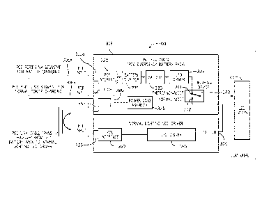
[0030] Fig. 3 shows an emergency POE luminaire 300 using two POE port
link
segments 305a, b. The luminaire 300 includes two POE inputs 310a, b, each POE
input being
connected respectively to a POE port link segment 305a, b. POE port link
segments 305a, b are
connected to unillustrated power sourcing equipment, such as a POE enabled
such, hub or
midspan (i.e., injector). Both POE inputs 310a, b are electrically connected
to POE emergency
battery pack 315. Battery pack 315 includes POE interface 320, which is
connected to a first
POE port link segment 310a via input 305a. Battery pack 315 also includes a
battery charger
325, battery 330, and LED driver 335. POE interface 320 extracts DC power
(supplied, for
example, as 48Vdc) from the POE port link segment 310a, and supplies that
power to battery
charger 325. Battery charger 325 steps down the voltage supplied by POE
interface 320 and
performs certain current conditioning functions.
[0031] An exemplary POE interface suitable for use as POE interface 320
is illustrated
in additional detail in Fig. 9. The POE interface 900 of Fig. 9 performs
several functions. First,
it extracts DC power from RJ45 connector 905 via the center-tap of the data
transformers 910a,
b which are connected on the primary-side to a POE link segment. Additionally,
POE interface
functions to separate data flow 915 from power flow and to couple both data
and power to the
application 920 (i.e., the functional components of the PD containing the POE
interface). POE
interface 900 includes an RJ45 connector 905, data transformers 910a, b with
center-tap
primary, bridge rectifier(s) 925, signature circuitry 930, classification
circuitry 935, an intelligent
6
CA 02952671 2016-12-15
WO 2016/149549 PCT/US2016/022964
switch over-current isolation "active-switch" with pass-FET 940, and a DC/DC
isolation power
converter 945.
[0032] After the POE interface 900 extracts DC power from the RJ45
connector via the
center-taps of the data transformers 910a, b, the power is coupled to an input
diode bridge 925
which protects the circuitry within the PD from being connected to a reverse
polarity input
voltage by accepting either positive or negative polarity inputs. Power is
then "intelligently"
supplied to the PD by the PSE (connected on the other side of the POE link
segment) via a
communications protocol via the "physical" (PHY) layer compliant to the IEEE
802.3xx
standard. DC power is supplied by the PSE at a nominal target voltage of 48
Vdc. The
"power-up" process follows a sequence where, once a PD is connected to the end
of the POE
Link Segment via the RJ45 connector 905, the PSE starts to raise the voltage
from 0 Vdc based
on the IEEE 802.3xx standard, with pre-determined levels, timing, and current
detection. The
sequence follows from left-to-right, from Signature to Classification to
Isolation to DC/DC to
Application. The first phase of the sequence (detection) of the powering
sequence occurs
when the PSE polls the connected PD to determine if it provides the correct
impedance
signature. The PSE accomplishes this by ramping up a current limited (5 mA)
detection
voltage (from 2.5 V to 10 V) across the designated pairs of CAT-x wires (at
about a 2 ms
repetition rate) and measuring the voltage and the current at the end of the
ramp time. If the
PSE detects the proper signature impedance in accordance with the IEEE 802.3xx
standard, it
determines that there is a valid PD at the end of the link. The PSE then
proceeds to the next
step in the process -- Classification. Classification is the process where the
PD "indicates" to
the PSE the required power range it will need. There are 5 categories
(classes). During
classification, the PSE induces 15.5-20.5 Vdc, limited to 100 mA, for a period
of 10 to 75 ms
responded by a certain current consumption by the PD, indicating its power
class. The
sequence advances to the next step where the PSE raises the voltage to 34 Vdc,
and the PD
"closes" the "Turn-on" switch (the Pass-FET in 940) but slowly controls inrush
current
consumption (of over 350 mA) within 50 ms. Once this step is completed, the
PSE ramps the
voltage up to 48 Vdc for the DC/DC isolation power converter 945 to supply
power to the
application 920. The application 920 for the POE emergency battery pack of
Fig. 3 is battery
charger 325.
[0033] Battery charger 325 is a high-frequency switch-mode power supply,
designed to
manage battery charging according to the battery charge capacity, size,
terminal voltage, type,
and other influencing factors with regards to energy usage and regional market
regulations or
restrictions. In certain embodiments, battery charger 325 is an isolated
"Flyback" topology
7
CA 02952671 2016-12-15
WO 2016/149549 PCT/US2016/022964
high-frequency switch-mode current source type with digital over analog
control. Other
topologies are used in other embodiments to best manage the chosen battery,
such as, a "Buck"
converter or a "Buck-boost" converter, or other topology, and either current
sourcing or current-
over-voltage sourcing may be used during the charging process, pulse-charge or
linear-charge,
constant-rate or multi-rate. Battery charger 325 may be designed to charge
different types of
batteries, such as, NiCd, NiMH, Pb-based, or Li-based. Where battery 330 is a
NiCd battery,
battery charger 325 is a "smart-charger" capable of supplying 1 to 3 Watts of
power during
recharge phase, and less than 1 Watt during maintenance-mode charging. In
normal operation
battery charger 325 provides a trickle charge, (supplied at 1.2 to 20 Vdc and
a nominal current
range of between 30 mA and 300 mA for typical NiCd type batteries; however,
these voltage
and current values depend on the type, pack design, and charge state of
battery 330) to battery
330.
[0034] Battery 330 supplies DC power to LED driver 335 at 2.4 to 24 Vdc,
with the
most typical voltages 6 to 19.2 Vdc depending on the type of LED luminaire
345. In certain
embodiments, battery 330 is a rechargeable NiCd battery having a reserve
capacity of 2.5 to 3.0
amp-hours at 6 to 19.2 Vdc. Other embodiments use other battery types, such as
NiCd batteries
having a reserve capacity of 1.5 to 4.0 amp-hours at 2.4 to 24 Vdc (1.2
Vdc/cell), or Lithium
iron phosphate (LiFePO4) batteries having a reserve capacity of 0.5 to 3.0 amp-
hours at 3.0 to
3.6 Vdc/cell.
[0035] In certain embodiments, LED driver 335 is a switch-mode power
converter that
powers the LED lamp(s) with power (Energy/time) provided by battery 330, and
supplies DC
current at a nominal 0.08 to 2.0 A over a voltage range from 10 to 60 Vdc to
LED lamps 345 via
relaying device 340. The LED current supplied in these embodiments is a pure
DC current, or
DC current with low AC ripple.
[0036] In alternative embodiments, LED driver 335 is a DC-DC "Flyback"
topology
high-frequency switch-mode power supply with Pulse-Width Modulation (PWM)
control
(digital or analog), where the output Voltage or Current or Power are
regulated. In these
embodiments, PWM current is passed through the LEDs. Other topologies are used
in other
embodiments, such as, a "Buck" converter or a "Buck-boost" converter, or Half-
Bridge
converter, or Full-Bridge converter, or other topology. The typical LED power
levels for
Emergency-Mode operation range from 3 to 25 Watts, with other power levels
possible. The
typical LED voltage ranges from 10 to 60 Vdc for Class 2 operation, with other
voltages
possible.
8
CA 02952671 2016-12-15
WO 2016/149549 PCT/US2016/022964
[0037] LED lamps 345 vary in operating voltage, current, power, and light
output,
depending on the embodiment. The typical LED lamps for LED fixtures are
offered over a large
range of different types for large area lighting range in voltage from 10 to
60 Vdc for Class 2,
and higher voltages for non-class 2. LED fixture lamp arrays & modules operate
over a wide
range of current levels from 0.08 Adc to 3 Adc. Color temperatures for LED
lamps 345 range
from 2500 K (warm-white) to 6000 K (bright-white), depending on the
embodiment.
[0038] Relaying device 340, in one embodiment, is an electromechanical
switch that
alternatively couples one of two inputs (341, connected to emergency battery
pack 315, or 342,
connected to normal lighting LED driver 350) to LED lamps 345. Use of an
electromechanical
switch as relaying device 340 is advantageous because it results in near-zero
insertion loss for
battery pack 315, i.e., when battery pack 315 is not connected, normal
lighting LED driver 350
is connected to led lamps 345 with minimal electrical resistance. This
invention or any
embodiments are not limited to only an electromechanical switch as the
relaying device,
alternate relaying devices such as diodes or solid-state switches or other
types are possible and
within the scope of the invention.
[0039] POE power link segment 305b is electrically connected through the
battery
pack's second POE input 305b to normal lighting LED driver 350 via normal
lighting POE input
355. Normal lighting LED driver 350 includes a POE interface 360, which
extracts DC power
available on the second POE link segment 310b (i.e., 48Vdc), and supplies it
to LED driver 365.
Like emergency backup LED driver 335, LED driver 365 has different operating
parameters
depending on the embodiment. In one embodiment, LED driver 365 is optimized to
operate
over a large range of voltages from 10 to 60 Vdc for Class 2, and higher
voltages for non-class
2. Such a driver can supply a large range of current levels operate over a
wide range of current
levels from 0.08 Adc to 3 Adc. The POE power levels are limited currently to
about 55 Watts
each, however, with future developments allowing up to near 90 Watts,
additional higher power
LED drivers and higher power luminaires are possible and within the scope of
the invention.
LED driver 365 is electrically connected through output 370 to an input of
relaying device 340,
and then, depending on the state of relaying device 340, to LED lamps 345.
[0040] In normal lighting operation, LED lamps 345 are driven from normal
lighting
LED driver 350, which takes DC power from power link segment 305b, which is
supplied in a
pass-through fashion through emergency battery pack 315. Emergency battery
pack 315 further
includes a power loss monitor 375, which monitors the status of power being
supplied to the
second POE input 305b by monitoring pass-through loop 380 between the second
POE input
9
CA 02952671 2016-12-15
WO 2016/149549 PCT/US2016/022964
305b and POE output 385. POE output 385 is in turn connected to normal
lighting driver POE
input 355.
[0041] When the luminaire 300 of Fig. 3 is in normal lighting mode,
relaying device 340
is set such that its second input 342 is electrically connected to LED Lamps
345. This results in
current being supplied from normal LED lighting driver 350 to LED lamps 345.
As will be
discussed further in relation to the battery pack of Fig. 4, when power loss
monitor 375 detects a
power down condition on pass-through loop 380, relaying device 340 switches
states such that
its first input 341, which is connected to emergency LED driver 335 to LED
lamps 345.
[0042] The luminaire described with respect to Fig. 3 has certain
advantages. Because
the luminaire uses two, independent POE link segments, one for charging the
backup battery and
another for driving the LED lamps under normal lighting conditions, the
luminaire of Fig. 3
minimizes the likelihood of corrupting or otherwise interfering with the
fidelity of data being
transmitted or received over the second POE link segment 305b. This may be
helpful if link
segment 305b is being used for communication as well as for the supply of DC
power.
Moreover, existing lighting and building codes, for example, NFPA 70 National
Electrical Code,
NFPA 101 Life-Safety code, and UL 924 Standard for Safety Emergency Lighting
and Power
Equipment, require that, for emergency backup lighting, unswitched power
(i.e., normal lighting
power), be monitored at the entry point of a luminaire. This is accomplished
in the luminaire of
Fig. 3, because power loss is monitored at input 310b to luminaire 300. This
arrangement is also
advantageous because it locates all critical components of the emergency
luminaire within the
luminaire, which minimizes the risk of hazards that might cause failure of the
emergency
lighting luminaire due to tampering, smoke, flood, fire, icing, vandalism, or
other adverse
conditions.
[0043] Fig. 4 schematically illustrates an emergency battery pack 400
useable in a
luminaire having two independent POE links, for example, luminaire 300
discussed above in
reference to Fig. 3. The battery pack 400 includes two POE inputs, one for
battery charging
410a, and a second for power for normal operation conditions 410b, which is
passed through
battery pack 400 to a POE output 485. The charging POE input is connected to
POE interface
420, which extracts DC power from the connected POE link and supplies that
power to battery
charger 425. Battery charger 425, in normal operating conditions, charges
battery 430. Battery
430 supplies LED driver 435, which is connected to a first input 441 of a
relaying device 440,
which in certain embodiments is an electro-mechanical switch. Relaying device
440
alternatively connects either its first input 441 or its second input 442 to
an output 443
electrically coupled to non-illustrated LED lamps. Second input 442 of
relaying device 440 is
CA 02952671 2016-12-15
WO 2016/149549 PCT/US2016/022964
connected to input 444, which when battery pack 400 is installed, receives
normal lighting
power from a normal lighting LED driver.
[0044] The battery pack 400 of Fig. 4 also includes a power loss monitor
475, which
detects a loss of power on pass-through loop 480. Upon detection of a loss of
power by power
loss monitor 475, a controller 490, which in certain embodiments is a
microprocessor in
communication with a non-illustrated memory, switches relaying device 440 such
that its first
input 441 is connected to output of the battery pack 443. Controller 490, in
certain
embodiments, includes additional functionality. For example, upon detecting a
power loss
condition, controller may send a signal via I/0 ports 495a, b to an external
or internal signaling
or indication device, indicating the detection of power loss conditions. In
certain embodiments,
controller 490 sends a derangement signal to one of ports 495a, b upon
detection of a loss of
normal lighting power. In some embodiments, derangement signal illuminates an
LED to alert
users that the emergency lighting system has been triggered. In some
embodiments, controller
490 sends additional data communications signals to ports 495a, b to be
connected to other
external devices, for example, over Ethernet links connected to ports 495a, b.
Such signals may
inform remote Ethernet connected devices of the status of battery pack 400,
the occurrence of a
power loss condition, and any other useful information. Controller 490 also
optionally receives
input control signals via ports 495a, b. Exemplary input control signals
include test signals to
simulate a power loss condition to test the functionality of battery pack 400,
or status queries for
controller 490. In certain embodiments, controller 490 communicates with other
external
devices such as a normal lighting LED driver (e.g., 350 in Fig. 3) or a data
logger.
[0045] Fig. 5 is a schematic illustration of an alternative embodiment of
a luminaire
using an emergency lighting battery pack fed by auxiliary power directed from
a normal lighting
LED driver. Unlike the embodiment of Fig. 3, the embodiment of Fig. 5 relies
on only a single
POE port link segment 505, with supplies DC power (as well as data
communications, in some
embodiments) to normal lighting LED driver 510 through POE input 515. As in
the
embodiment of Fig. 3, POE interface 520 extracts DC power from POE link
segment 505 and
supplies it to LED driver 520. In normal lighting operating conditions, LED
driver 525 supplies
driving current to LED lamps 585 through driver output 530 and first input 582
of relaying
device 580, which will be described in further detail in connection with
battery pack 550.
[0046] The embodiment of Fig. 5 also includes battery pack 550 for
supplying
emergency power to LED lamps 585 in the event of a power loss condition in
normal LED
lighting driver. Like the embodiment of Fig. 3, battery pack 550 includes a
battery charger 565,
which charges battery 570, which drives LED driver 575. The output of LED
driver 575 is
11
CA 02952671 2016-12-15
WO 2016/149549 PCT/US2016/022964
connected to a first input 581 of relaying device 580, which alternatively
connects its first or
second inputs 581, 582 to LED lamps 585, such that power can be switched from
normal
lighting LED driver 530 to battery pack 550 in the event of the detection of a
normal lighting
power loss condition.
[0047] Unlike the embodiment of Fig. 3, the luminaire 500 of Fig. 5 does
not use two
POE link segments. Instead, a one-port method is enabled by extracting a low
level of DC
power from the normal lighting power supplied to normal lighting LED driver
510 by an
auxiliary power output interface 535. This power is extracted from the POE fed
DC supply
being coupled to an aux power output interface 535 after the POE Interface 520
has separated
Data flow from Power flow, or in other implementations at any point before or
after the
interface. In one embodiment, DC power (0 to 3W) is extracted at the nominal
POE voltage of
48 Vdc (36 ¨ 57 Vdc range) on POE input 515 to driver 510, and is supplied via
output 540,
auxiliary power link 545 and power input 555 to battery pack 550. The DC power
interface
converter 560 controls (i.e., by limiting in-rush current, filtering noise bi-
directionally, and
buffering) the 48 Vdc supply that feeds the supplied power to operate Battery
Charger 565.
[0048] In accordance with this arrangement, the input voltage of the
Battery Charger
565, in one embodiment, is a nominal 48 Vdc (36 ¨ 57 Vdc range). The output
voltage of the
Battery Charger 565, in the same embodiment, typically floats to the nominal
battery voltage of
Battery 570 of 9.6 Vdc +/- 20 % fully charged, or simply Vbatt float for other
particular
batteries. Chargers in other embodiments are capable of supporting other
battery voltages within
a typical range of between 2.4 and 24 Vdc. The battery charge current is
dependent on charge
level, time, application, and battery type, ranging from 0.0 Adc (no charge
current) up to 1C,
where C is the battery charge capacity equivalent current expressed in Adc.
Values of C
supported by embodiments of the invention include 1.2 A, 1.5 A, 2 A, 2.2 A,
2.5 A, 3 A, 3.5 A,
4 A, with C = 3 A being the most typical for POE lighting.
[0049] The input of the LED Driver 575 is coupled to the Battery 570 at
the battery
nominal terminal voltage +/- 20% and ranges to 1 V/cell at the end of the
discharge cycle. In a
typical embodiment, the typical battery voltage, fully charged, is
approximately 9.6 Vdc for an
8-Cell NiCd battery. The input current of the LED Driver 575 is dependent on
battery voltage,
output power, and efficiency. The typical input current of the LED Driver 575
is approximately
1.7 Adc for a 9.6 Vdc battery voltage.
[0050] For emergency-mode operation LED driver 575 is connected to first
input 581 of
relaying device 580, which connects to LED lamps 585. The LED Driver 575 is
capable of
driving LED lamps 585 over a large range of voltages from 10 to 60 Vdc for
Class 2, and higher
12
CA 02952671 2016-12-15
WO 2016/149549 PCT/US2016/022964
voltages for non-class 2, and over a large range ranging from 0.08 Adc to 2
Adc, with higher
current levels possible in the future. The POE power levels are limited
currently to about 55
Watts each, however, with future developments allowing up to near 90 Watts.
[0051] In the embodiment of Fig. 5, a normal lighting loss of power is
detected by
power loss monitor 590 in battery back 550. In this embodiment, loss of power
at normal
lighting LED driver 510 (for example, because power has been lost on POE port
link segment
505 results in loss of power on auxiliary power link 545 such that the power
loss can be detected
at battery pack 550. This maintains the advantages of the system described in
reference to Fig.
3, where power may be lost at any point up to the luminaire without impacting
the functionality
of the emergency illumination system.
[0052] As in the embodiment of Fig. 4, the battery pack 550 includes
controller 595,
which, at least, switches relaying device 580 in response to detection of a
power loss condition.
Controller 595 optionally has additional functions in additional embodiments,
which are
described more fully below in reference to Fig. 6.
[0053] Fig. 6 schematically illustrates an emergency battery pack 600
useable in a
luminaire having one POE port link segment, for example, luminaire 500
discussed above in
reference to Fig. 5. Like the battery pack described in Fig. 4, battery pack
600 includes
controller 655, but also includes I/0 ports 665a, b for two-way communications
with external
devices, for example, for receiving test signals and status queries, and for
sending status data and
a derangement signal in the case of a power loss condition.
[0054] Fig. 7 schematically illustrates a POE backup luminaire 700
according to another
embodiment of the invention. In the embodiment of Fig. 7, like that of Fig. 5,
the luminaire
receives power over a single POE port link segment 702. Unlike the embodiment
of Fig. 5, POE
link segment 702 is first connected directly to battery pack 705. A POE port
interface with
integral power bridge ("IIPB") 715 extracts a low level of DC power to provide
to battery
charger 720, which charges battery 725, to supply LED driver with power to
drive LED lamps
750 in the event of a power loss condition as has been described.
[0055] IIPB 715 operates to provide an isolated data link, as will as a
DC power link
from link segment 702 to the normal lighting LED driver. IIPB also extracts or
bridges a low
level amount of power from link segment 702 to battery charger 720. From a
systems level
perspective, link segment 702 is a dedicated link segment for normal lighting
purposes, data and
power over one single link segment. IIPB 715 enables the capability to
maintain this single-
purpose usage, while power is used also to power the battery charger 720.
Power is provided
from the PSE normal power supply via link segment 702 to the normal lighting
LED driver 705
13
CA 02952671 2016-12-15
WO 2016/149549 PCT/US2016/022964
according to the IEEE 802.xx POE standard, which supports active and
intelligent
communication between the PSE normal power supply and the normal lighting LED
driver 705.
IIPB 715 is an intelligent power extractor, extracting a low level of power
from the normal
lighting POE link segment to provide power to battery charger 720, in such a
way so as to not
disturb or interfere with the data communications or the power flow between
the PSE and the
normal lighting driver 705. Each POE port link segment is intended as a
dedicated link between
the PSE and the PD (in this case, the normal lighting LED driver). The IIPB is
transparent in
this process and does not communicate over the POE Port Link Segment 702.
[0056] As in previous embodiments, controller 747 detects a power loss
condition and
switches relaying device 740 to connect battery 725 to led lamps 750. Unlike
in previously
described embodiments, a power loss condition is detected in the battery pack
705. Power loss
monitoring is a shared function, with initial monitoring integrally within the
IIPB 715, and
additionally supported by the electronic Controls 747.
[0057] Fig. 8 schematically illustrates an emergency battery pack 800
having a power
bridge 810, useable in a luminaire having one POE port link segment connected
to input 805.
Such a luminaire is usable as a battery pack in, for example, luminaire 700
discussed above in
reference to Fig. 7. Like the battery pack described in Figs. 4 and 6, battery
pack 800 includes
controller 840, but also includes I/0 ports 845a, b for two-way communications
with external
devices, for example, for receiving test signals and status queries, and for
sending status data and
a derangement signal in the case of a power loss condition.
[0058] Fig. 10 illustrates a pair of power loss monitor circuits, each of
which is usable
for the power loss monitor 375 described above in reference to Fig. 3. Fig. 10
illustrates two
circuits, 1005, which detects power loss on Port 1 (between pins 1 and 3) of
an attached RJ45
POE cable 1015, and 1010, which detects power loss on Port 2 of the same cable
(between pins
4 and 7). In the discussion to follow, reference will be made to the Port 1
circuit 1005 primarily,
which involves circuit components R22, D21 ¨ D24, D25, D26, U4, U5, FB5, and
FB6;
however, it should be understood that the discussion likewise applies to the
adjacent circuit 1010
for Port 2.
[0059] As is set forth above with respect to Fig. 1, power extraction in
POE typically
occurs on a powered device's data transformer (e.g., 125a and 125b in Fig. 1),
specifically from
the "center-tap" of a twisted pair transformer winding (the PD data
transformer primary). As
shown in Figure 1, these terminations (referenced to the RJ45 connector) are
pin sets (1,2 ¨ 3,6)
and (4,5 ¨ 7,8). Turning now to Fig. 3, because the luminaire of Fig. 3 uses
two separate POE
links (a separate dedicated emergency link for battery charging and a separate
link for the
14
CA 02952671 2016-12-15
WO 2016/149549 PCT/US2016/022964
normal lighting LED driver), access to the PD data transformer (located at POE
interface 360,
for example) for the normal lighting POE link is not provided for the power
loss monitor (e.g.,
375). Embodiments of the invention solve this problem by recognizing that the
POE voltage is
DC and of equal value (ideally) on each of the pin-pairs; i.e., Vpinl = Vpin2,
and Vpin3 =
Vpin6, etc. Therefore, the nominal voltage Vpinl ¨ Vpin3 = +/- 48 Vdc.
Likewise, the nominal
voltage Vpin2 ¨ Vpin6 = +/- 48 Vdc. Likewise, the nominal voltage Vpin4 ¨
Vpin7 = +/- 48
Vdc. Likewise, the nominal voltage Vpin5 ¨ Vpin8 = +/- 48 Vdc. A terminating
circuit across
any of these pin-sets (i.e., any pair of pins, where each pin is associated
with its own twisted pair
in the cable) is then used to measure and detect the power on a given port.
Minimum data
interference can be achieved because the resulting dc current i monitor is
relatively low and is
of a common mode dc signal.
[0060] One novel advantage of this method and system of detecting a loss
of POE
power is the minimization of noise and interference that is achievable by DC
current flow
differentially only between two pair sets (across the supply terminals
differentially imposed)
rather than across any one digital data pair. The low level DC current is
imposed as a common-
mode current for each data pair, but is differentially imposed between data
pair sets. The data
pairs respond only to differential signals within the pair, and reject common-
mode signals.
Furthermore, data signals are AC, differential-mode for each twisted pair;
therefore, AC
interference to the data signals is minimized by the "non-differential-mode"
of i monitor, rather
it is common-mode DC across pair sets. What is more, this power loss monitor
connectivity
method remains valid for both Alternatives A or B shown in Fig. 1.
[0061] In the circuits of Fig. 10, port power "On" or "Off' is detected
by Opto-Coupler
U5 (or like-wise U6 on port 2), where the output signal is a digital signal -
Port power "On"
status results in current flow in the Opto-Coupler sufficient to drive the
output transistor of the
opto-coupler to the "On" state. The Opto-Coupler is a "High-Gain" device,
where minimum
current through the opto-coupler's input LED is desired, which allows for the
detection of power
on with very low power use. Additionally, opto-coupler U5 provides galvanic
isolation
(isolating functional sections of electrical systems to prevent direct current
flow), which
provides maximum prevention of noise interference between circuits.
[0062] In the circuits of Fig. 10, current is provided through the opto-
coupler U5 via
bridge rectifier 915, resulting in the power loss monitor being compatible for
each of the
possible polarity implementations (see D21-D24 of circuit 1005 of Fig. 10).
[0063] The circuit of Fig. 10 includes two Zener diodes in series (D25,
D26) connected
to opto-coupler U5 as shown. The first Zener diode D25 is connected in series
with the Opto-
CA 02952671 2016-12-15
WO 2016/149549 PCT/US2016/022964
Coupler's input LED, which provides intended current flow only when the port
input operating
voltage exceeds the D25's breakdown voltage (Vb), thereby providing a voltage
reference
means. When the voltage across a D25 exceeds its Vb value, D25 "turns on" and
passes current
according to the familiar I-V curve for a Zener diode, causing current flow to
increase sharply as
the voltage continues to rise above Vb. In the arrangement of Fig. 10, as the
POE port input
operating voltage rises from 0 Vdc up to the nominal value of 48 Vdc, the
component values are
selected such that at the desired port voltage the circuit "turns on" sharply
allowing current to
flow and then to increase in magnitude as the input port voltage exceeds Vb.
In this manner, the
POE power "On" threshold voltage (the minimum Input Operating Voltage of 37
Vdc) is
"measured" and a circuit response is initiated. Zener diode D25 and its
functions are understood
by those skilled in the art to be easily implemented additionally utilizing
Integrated Circuits and
programmable devices.
[0064] As can be seen in Fig. 10, the circuit additional and optionally
includes a series
resistor R22, the Opto-Coupler's input LED, and the two series Zener Diodes
D25, D26. The
total Zener diode breakdown voltages (the two Zener diode Vb values together)
are selected to
set the circuit response (the point at which the digital output of the Opto-
coupler U5 changes
states). Therefore, the circuit comprised of series resistor R22, the Opto-
Coupler, and the two
series Zener Diodes (D25 & D26), form a functional Analog-to-Digital
converter.
[0065] The circuit of Fig. 10 additional and optionally includes certain
features that
provide hysteresis. Hysteresis is the time-based function of a system's output
on present and
past input variables. The dependence arises because the history affects the
value of an internal
state. To predict its future output state, either its internal state or its
history must be known. In
the circuit of Fig. 10, as the input voltage approaches the circuit "threshold
voltage," there
becomes an increasing depletion of "noise immunity" where the output state
change as a
function of the input voltage level becomes highly unstable. The design of
Fig. 10 provides
sufficient values of hysteresis to mitigate against circuit response
instability and ambiguity.
[0066] The circuit of Fig. 10 includes an isolated hysteresis sub-
circuit, comprised of
components D26, U5, and feedback from non-illustrated Power Monitoring Control
circuitry,
contained, for example, in the controllers described above. Isolation is
accomplished by use of
Opto-coupler U5. Hysteresis is accomplished by setting the "turn-on" voltage
level higher than
the "turn-off' voltage level. An exemplary method of accomplishing this,
implemented in one
embodiment of the invention, is to first split the total Zener diode breakdown
voltage Vb total
into two separate Zener diodes (D25 & D26). The breakdown voltage Vb D26 is a
small
fraction of the total; furthermore, Vb D26 < Vb D25. As the port input voltage
rises from 0 to
16
CA 02952671 2016-12-15
WO 2016/149549 PCT/US2016/022964
48 Vdc, with the circuit "turn-on" threshold voltage set at 37 Vdc, the Opto-
coupler responds
with a circuit response by changing digital states on its output transistor.
The output of Opto-
coupler U4 feeds a monitor and a control circuit which then couples back into
the Power Loss
Monitor in the form of information feedback via Opto-coupler U5. The output of
U5 (a
transistor) is connected to bypass Zener Diode D26. As U5 changes states from
"off' to "on,"
its output transistor diverts current flow around D26, collapsing the D26
Zener voltage to near
zero volts. The total Zener Diode breakdown voltage is thus reduced by the
value of Vb D26.
The circuit "threshold" voltage is reset to a lower voltage (30 Vdc), known as
the "Falling input
voltage." The output state of Opto-coupler U4 will not change states until the
input voltage is
falling and decreases to less than 30 Vdc. The differential voltage between
"turn-on" (37 Vdc)
and the "turn-off' voltage (30 Vdc) is 7 V, and is referred to as the
hysteresis voltage.
[0067] The power loss monitor circuit of Fig. 10 also includes features
to attenuate cross
talk and filter noise. Ferrite beads FB5 & FB6 are placed such that they
function as low-pass
filters, attenuating high-frequency noise energy. They are in effect series
inductors in the circuit.
Therefore, the ferrite beads block high-frequency current, enabling
attenuation of high-
frequency noise coupled into the data pairs.
[0068] While the preferred embodiments of the present invention have been
illustrated
in detail, it should be apparent that modifications and adaptations to those
embodiments may
occur to one skilled in the art without departing from the scope of the
present invention.
17