Note: Descriptions are shown in the official language in which they were submitted.
CA 02952686 2016-12-16
TELESCOPIC HANDLE FOR PIECES OF LUGGAGE
The invention relates to a telescopic handle for pieces of
luggage, in particular travel suitcases, having an outer
telescopic tube assembly, which is arranged on the piece of
luggage in a fixed manner, an inner telescopic tube assembly,
which can be accommodated in and pulled out of the outer
telescopic tube assembly, and a handle part, which is arranged
on the end of the inner telescopic tube assembly that can be
pulled out of the outer telescopic tube assembly, wherein the
telescopic handle can be adjusted from a rest position thereof,
in which the inner telescopic tube assembly is accommodated in
the outer telescopic tube assembly, to an operating position
thereof, in which the inner telescopic tube assembly is pulled
out of the outer telescopic tube assembly and the piece of
luggage can be moved and steered by means of the telescopic
handle.
Pieces of luggage, in particular travel suitcases, are nowadays
usually fitted with rollers and with a telescopic handle by
means of which the piece of luggage can be moved relatively
easily. These telescopic or pull-out handles have gained
acceptance because on the one hand when the piece of luggage is
to be stowed, they can be inserted in a space-saving manner into
the piece of luggage and on the other hand, when the piece of
luggage is to be moved, they can be pulled out to a certain
length. The advantage of these telescopic handles lies in the
fact that they can be adjusted independently of the size of the
respective piece of luggage to a comfortable handle height for
the respective user. In order to bring the telescopic handle
into its operating position in which the piece of luggage can be
1
I I
CA 02952686 2016-12-16
moved and manoeuvred by means therefore, the telescopic handle
is pulled out manually and the telescopic handle is retracted
manually to bring it back into the rest position.
Starting from the previously described prior art, it is the
object of the invention to further develop the generic
telescopic handle for pieces of luggage, in particular travel
suitcases in such a manner that its operating comfort is
increased considerably without changing its external dimensions.
This object is solved according to the invention whereby the
telescopic handle has a positioning and energy-storage device
20, by means of which the inner telescopic tube assembly can be
moved from a position thereof that corresponds to the rest
position of the telescopic handle and in which the inner
telescopic tube assembly is accommodated in the outer telescopic
tube assembly to an intermediate position, in which the inner
telescopic tube assembly is slightly pulled out of the outer
telescopic tube assembly and the handle part arranged on the
inner telescopic tube assembly can be comfortably encircled and
from which the handle part can be brought into the operating
position of the telescopic handle and that the positioning and
energy-storage device is integrated inside the outer and inner
telescopic tube assembly of the telescopic handle. In the case
of the telescopic handle configured according to the invention,
in the rest position of the telescopic handle, the handle part
connected to the inner telescopic tube assembly can be
accommodated or inserted completely in a fixed handle guide
housing in relation to the outer telescopic tube assembly since
a manual actuation of this handle part as such is not necessary
in the rest position of the telescopic handle. By means of the
2
CA 02952686 2016-12-16
positioning and energy-storage device provided according to the
invention, the inner telescopic tube assembly and with this the
handle part provided in a fixed manner on the inner telescopic
tube assembly can be brought into the intermediate position in
which the handle part can be easily handled in the usual manner.
By integrating the positioning and energy-storage device in the
cavity formed inside the telescopic tubes of the telescopic
handle, it is achieved that the dimensions of the telescopic
handle are not increased as a result of the presence of the
positioning and energy-storage device.
In particular in the case of comparatively small travel
suitcases or items of luggage, it is advantageous if an
intermediate telescopic tube assembly is arranged between the
inner telescopic tube assembly and the outer telescopic tube
assembly. The intermediate telescopic tubes are usually
connected to the inner and outer telescopic tubes. As a result
of the presence of the intermediate telescopic tube assembly,
the operating position of the telescopic handle can be adjusted
over a larger longitudinal range.
Expediently a positioning and energy-storage device is provided
per telescopic tube of the inner telescopic tube assembly. This
results in an equalization of the forces which must be exerted
and transmitted between the individual telescopic tubes of the
telescopic handle.
According to an advantageous further development of the
telescopic handle according to the invention, the positioning
and energy-storage device thereof can be actuated by means of a
handle arranged adjustably on the handle part, by means of which
3
i I
I
CA 02952686 2016-12-16
a locking element arranged in the inner telescopic tube assembly
can be moved into and out of engagement with a locking member
arranged in the outer telescopic tube assembly or in the
intermediate telescopic tube assembly.
Advantageously the locking member arranged in the outer
telescopic tube assembly or in the intermediate telescopic tube
assembly, preferably pressed into the outer telescopic tube
assembly or into the intermediate telescopic tube assembly can
be configured as a lower end section of a toothed rod extending
along the outer telescopic tube assembly or the central
intermediate telescopic tube assembly, wherein the toothed rod
has the lower end section with which the locking element
arranged in the inner telescopic tube assembly is in engagement
in the rest position of the telescopic handle, a sliding section
which extends above the lower end section of the toothed rod and
in which the locking element arranged in the inner telescopic
tube assembly cannot engage, and an upper section which extends
above the sliding section of the toothed rod and in which the
locking arrangement arranged in the inner telescopic tube
assembly can engage quasi-continuously.
In order to achieve the locking in a mechanically constructively
comparatively simple manner, it is proposed that the locking
element arranged in the inner telescopic tube assembly is pre-
tensioned in the direction of the toothed rod and can be moved
out of engagement with the toothed rod by means of an actuator
connected to the handle on the handle part side. When in the
rest position of the telescopic handle accordingly the
engagement between the locking element on the handle part side
and the toothed rack is cancelled by means of the handle, the
4
h
CA 02952686 2016-12-16
positioning and energy-storage device of the telescopic handle
is automatically put into operation, by means of which the inner
telescopic tube assembly is raised from the outer telescopic
tube assembly or from the intermediate telescopic tube assembly.
Advantageously the actuator is connected to the handle on the
handle part side by means of a tension means and can be moved in
the longitudinal direction of the inner telescopic tube assembly
wherein the actuator furthermore has a sloping surface
arrangement by means of which the longitudinal movement can be
converted into an adjustment of the locking element arranged in
the inner telescopic tube assembly directed in the transverse
direction of the inner telescopic tube assembly, by means of
which the locking element arranged in the inner telescopic tube
assembly can be moved out of engagement with the toothed rod.
According to a particularly advantageous embodiment of the
telescopic handle according to the invention, a tilting lever is
pivotable by means of the handle thereof, by means of which the
actuator is movable in the longitudinal direction of the inner
telescopic tube assembly by means of the tension means.
In order to be able to adjust or displace the actuator connected
to the locking element in a defined manner, it is proposed that
the actuator is displaceable in an adjusting chamber firmly
inserted in the inner telescopic tube assembly, preferably
pressed in.
The positioning and energy-storage device of the telescopic
handle according to the invention advantageously comprises a
compression spring which in the rest position of the telescopic
CA 02952686 2016-12-16
handle is compressed between the inner telescopic tube assembly
and the outer telescopic tube assembly or the intermediate
telescopic tube assembly. By this means, on the one hand the
possibility is afforded that upon release of the compression
spring, the inner telescopic tube assembly is raised by a pre-
definable stroke from the outer telescopic tube assembly or from
the intermediate telescopic tube assembly, wherein furthermore
in a mechanically constructive less complex manner,
possibilities can be achieved by means of which the compression
spring can be compressed in a suitable manner when pushing
together the telescopic handle.
Advantageously the compression spring of the positioning and
energy-storage device of the telescopic handle according to the
invention holds a drive or lifting rod which in the rest
position of the telescopic handle can be clamped between the
tensioned compression spring and the outer telescopic tube or
the central telescopic tube.
Advantageously by means of the compression spring, after
cancelling the engagement between the locking element arranged
in the inner telescopic tube assembly and the lower section of
the toothed rod arranged in the outer telescopic tube assembly
or in the intermediate telescopic tube assembly, the inner
telescopic tube assembly can be raised from the outer telescopic
tube assembly or the intermediate telescopic tube assembly by a
stroke length corresponding to the length of the sliding section
of the toothed rod and the locking element. This ensures that
the locking element on the handle part side comes into
engagement with the upper section of the toothed rod, wherein in
this position of the locking element on the handle part side and
6
i I
I
CA 02952686 2016-12-16
therefore of the handle part, the telescopic handle adopts its
intermediate position.
The stroke length is advantageously about 20 mm.
The invention is explained in detail hereinafter by means of an
embodiment with reference to the drawings. In the figures:
Figure 1 shows a section view of one embodiment of the
telescopic handle according to the invention for pieces
of luggage in which the telescopic handle is in the
rest position;
Figure 2 shows a view of the embodiment of the telescopic handle
according to the invention shown in Figure 1, wherein
an inner telescopic tube assembly of the telescopic
handle is located in an intermediate position;
Figure 3 shows a sectional view of a positioning and energy-
storage device of the telescopic handle according to
the invention in the intermediate position shown in
Figure 2;
Figure 4 shows a view of the embodiment of the telescopic handle
according to the invention shown in Figures 1 to with
the inner telescopic tube assembly located in its
completely pulled-out form; and
Figure 5 shows a sectional view of the positioning and energy-
storage device of the telescopic handle shown in
7
I
CA 02952686 2016-12-16
Figures 1 to 4 in the pulled-out end position of the
inner telescopic tube assembly.
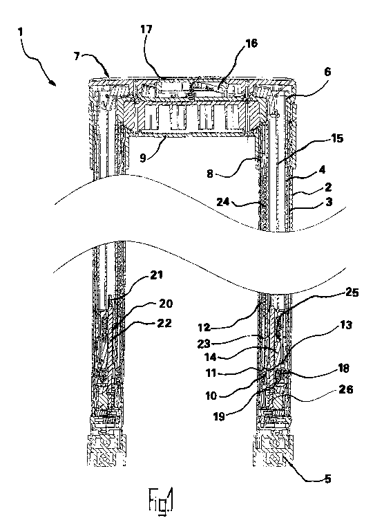
A telescopic handle 1, also called pull-out handle, according to
the invention, shown in different positions in Figures 1 to 5
and explained hereinafter, is used to move pieces of luggage, in
particular travel suitcases or similar containers, not shown in
the figures.
In the exemplary embodiment shown, the telescopic handle 1 has
an outer telescopic tube assembly formed of two outer
telescopic tubes 2, a central telescopic tube assembly or
intermediate telescopic tube assembly formed of two central
telescopic tubes 3, wherein the central telescopic tube 3 is in
each case arranged inside the outer telescopic tube 2, and an
inner telescopic tube assembly formed from two inner telescopic
tubes 4, wherein the inner telescopic tube 4 is in each case
arranged inside the central telescopic tube 3.
The central telescopic tubes 3 are each connected to the outer
telescopic tubes 2 or the inner telescopic tubes 4 in a
telescopic manner so that they can be pulled out and pushed in.
The two outer telescopic tubes 2 are firmly connected to the
piece of luggage by means of spacers 5.
The two inner telescopic tubes 4 are connected to one another by
means of a handle part 7 at the ends 6 thereof which can be
pulled out from the outer telescopic tubes 2.
8
CA 02952686 2016-12-16
The two outer telescopic tubes 2 are - as already mentioned -
attached in a fixed manner to the piece of luggage not shown in
Figures 1 to 5. At the upper ends 8 thereof in Figures 1 to 5,
the two outer telescopic tubes 2 are connected to one another by
means of a handle guide housing 9, wherein in a rest position of
the telescopic handle 1 in which the inner telescopic tubes 4
and the central telescopic tubes 3 are accommodated inside the
outer telescopic tubes 2, the handle part 7 of the telescopic
handle 1 is accommodated in the handle guide housing 9 of the
same.
The handle part 7 of the telescopic handle 1 can be locked by
means of a lock 10 in or on the handle guide housing 9.
To this end, the lock 10 comprises a locking member 11 arranged
in a fixed manner in the central telescopic tube 3 in the
exemplary embodiment shown. In the exemplary embodiment shown
the locking member 11 provided in a fixed manner in or on the
central telescopic tube 3 is configured as lower end section 11
of a toothed rod 12, which extends in the longitudinal direction
of the central telescopic tube 3 in the same. Furthermore, the
lock 10 includes a locking element 13 which can be brought into
and out of engagement with the lower end section 11 of the
toothed rod 12 provided as locking member.
The locking element 13 sits on an actuator 14 which is connected
via a tension means 15 which extends through the telescopic tube
assembly and a tilting lever 16 to a handle 17 accommodated on
the handle part 7
9
CA 02952686 2016-12-16
The locking element 13 is pre-tensioned by means of a transverse
spring element 18 in the direction of the toothed rod 12. A
sloping surface arrangement 19 is provided on the actuator 14.
When the actuator 14 is raised by actuating the handle 17 on the
handle part side via the tilting lever 16 and the tension means
15, the actuator 14 and with it the locking element 13 is moved
by the sloping surface arrangement 19 against the spring force
of the transverse spring element 18 in the radial direction of
the telescopic tube assembly so that the locking element 13
comes out of engagement with the lower end section 11 of the
toothed rod 12. As soon as the engagement between the locking
element 13 connected to the handle part 7 via the tension means
15 and the lower end section 11 of the toothed rod 12 arranged
in a fixed manner in relation to the intermediate telescopic
tube assembly 3 is cancelled, the inner telescopic tube assembly
4 is movable in relation to the intermediate telescopic tube
assembly 3.
In order to bring the handle part 7, which is accommodated
inside or on the handle guide housing 9 in the rest position of
the telescopic handle 1, into an intermediate position in which
the handle part 7 is readily encircled, the telescopic handle 1
has a positioning and energy-storage device 20. This positioning
and energy-storage device 20 includes a compression spring 21
which is arranged on the inner telescopic tube 4 and on which a
lifting or drive rod 22 is fixed for its part.
In the rest position of the telescopic handle 1 shown in Figure
1 the positioning and energy-storage device 20 comprising the
compression spring 21 and the lifting or drive rod 22 is fixed
between the inner telescopic tube 4 and the central telescopic
CA 02952686 2016-12-16
tube 3 when the compression spring 21 is compressed. In the rest
position of the telescopic handle 1, the lifting or drive rod 22
abuts with its lower end against a stop 26 provided in the
central telescopic tube 3. As soon as the engagement between the
locking element 13 connected to the handle part 7 and the lower
section 11 of the toothed rod 12 connected to the central
telescopic tube 3 is cancelled, the inner telescopic tube 4 is
displaced in the upwards direction by means of the mechanical
energy stored in the compression spring 21 of the positioning
and energy-storage device 20.
Since the toothed rod 12 is formed with a toothing-free sliding
section 23 above its lower end section 11, after cancelling the
engagement between locking element 13 on the handle part side
and the locking member 11 provided on the central telescopic
tube 3, the actuation of the handle 17 need not be maintained.
The handle part 7 is moved in the upwards direction as a result
of the interaction between the positioning and energy-storage
device 20 and the central telescopic tube 3 or the stop 26
provided therein until the locking element 13 on the handle part
side is pushed directly above the sliding section 23 of the
toothed rod 12 by the transverse spring element 18 again into
engagement with a toothed upper section 24 of the toothed rod
12.
By actuating the handle 17 on the handle part side once, the
telescopic handle 1 can accordingly be brought from its rest
position shown in Figure 1 into its intermediate position shown
in Figures 2 and 3 whereby the handle part 7 of the telescopic
handle 1 is moved away from the handle guide housing 9 of the
11
CA 02952686 2016-12-16
telescopic handle 1 by a pre-definable stroke length and thus
can be embraced or gripped around in a simple and convenient
manner.
If the telescopic handle 1 is to be moved from the intermediate
position shown in Figures 2 and 3 into a pulled-out operating
position shown in Figures 4 and 5, the engagement between the
toothed upper section 24 of the toothed rod can be cancelled
again by renewed actuation of the handle. By this means the
inner telescopic tube 4 is movable relative to the outer
telescopic tube 2 until the operator has found a suitable
operating position of the telescopic handle 1 for him and ends
the actuation of the handle 17. In this operating position the
engagement between the locking element 13 on the handle part
side and the corresponding part of the upper section 24 of the
toothed rod 12 is accordingly made again. The telescopic handle
1 is now located in the operating position selected by the
operator. In Figures 4 and 5 the selected operating position of
the telescopic handle 1' is selected so that the locking element
13 on the handle part side at an upper end section of the
toothed rod 12 is in engagement with the same. Naturally other
operating positions of the telescopic handle 1 are also
possible. The adjustable handle 1 is adjustable quasi-
continuously between different operating positions according to
the dimensions of the upper section 24 of the toothed rod 12.
In order to ensure a defined sequence of the adjustment of the
actuator 14 brought about by means of the handle 17 on the
handle part side, the actuator 14 is displaceably accommodated
inside an adjusting chamber 25 firmly inserted or pressed in the
inner telescopic tube 4.
12
CA 02952686 2016-12-16
In order to bring or push the telescopic handle 1 from the
operating position shown in Figures 4 and 5 back into the rest
position shown in Figure 1, the handle 17 on the handle part
side must be actuated for the duration of the push-in process so
that the locking element 13 on the handle part side is loosened
or released from its locking with the upper section 24 of the
toothed rod 12. In this state the inner telescopic tube 4 and
the central telescopic tube 3 can be pushed back again into the
outer telescopic tube 2. As a result of the simultaneous
application of force to the handle part 7 in the direction of
the telescopic insertion as far as the stop, the positioning and
energy-storage device 20 or its compression spring 21 is pre-
tensioned again. On reaching the end position of the telescopic
handle 1 defined by a stop, the actuation of the handle 17 is
ended so that the locking element 13 on the handle part side is
brought into engagement with the locking member or the lower end
section 11 of the toothed rod 12.
The telescopic handle 1 has the same type of functional members
in both telescopic tubes in both inner telescopic tubes 4.
central telescopic tubes 3 and outer telescopic tubes 2, wherein
hereinbefore the description and operating mode have been made
for one outer telescopic tube 2, central telescopic tube 3 and
inner telescopic tube 4.
13