Note: Descriptions are shown in the official language in which they were submitted.
CA 02952743 2016-12-15
WO 2015/200774
PCT/US2015/037937
1
BRISTLED COMPONENT FOR PERSONAL-CARE APPLICATOR
FIELD OF THE INVENTION
The invention is directed to personal-care applicators, such as, e.g.,
cosmetic applicators.
More particularly, the invention pertains to a bristled component for a
personal-care applicator in
which bristles are attached to a support by ultrasonic welding.
BACKGROUND
Several types of personal-care applicators, such as, e.g., mascara brushes,
exist today,
including bristled applicators. Examples include, without limitation, twisted-
wire brushes, molded
brushes, and tufted brushes. Twisted-wire brushes have generally circular
fiber patterns. These
patterns can be formed or modified by trimming the fibers in post-wiring or
post-twisting steps,
which can provide various geometric and functional patterns. While a typical
process for making
twisted-wire brushes provides a manufacturer with an ability, albeit limited,
to vary the fiber type
and fiber diameter, the variety of available patterns, aside from those
achieved by trimming, is
generally restricted to essentially circular configurations and specific fiber-
density patterns, where
abutting bristles must have comparable thickness. Limited choices of fiber-
density patterns in the
twisted-wire brushes are predicated on the inherent lack of ductility of the
wire used to embed the
bristles. If, for instance, relatively thick bristles are placed next to
relatively thin bristles, the latter
may slip though gaps formed in the twisted wire to accommodate the thick
bristles (a so-called
"tenting" of the wire as it twists).
Manufacturing brushes by molding, such as, e.g., injection molding or casting,
allows one to
choose almost any desired pattern. But every new brush design would
necessarily require a new
mold, which makes manufacturing brushes by molding both expensive and
difficult to prototype.
Molding also typically requires a multi-cycle batch processing, which is time-
consuming. In
addition, injection molding and casting most typically result in bristle
patterns having a continuous
taper and/or a mold-parting line throughout the bristle length, to enable the
removal of the resulting
brush from the mold. The continuous taper may not be desirable in some brush
configurations; and
the parting line may affect the functionality of the bristles and be otherwise
perceived as
aesthetically objectionable.
CA 02952743 2016-12-15
WO 2015/200774
PCT/US2015/037937
2
Tufted brushes can be manufactured by a staple and/or process a hot-melt
process. These too
include certain limitations. A staple process, for example, usually requires
processing of identical or
similar fibers; hence their selection, volume, and distribution are typically
limited by the size of
fibers-receiving holes. A hot-melt process, on the other hand, is labor-
intense and can adversely
impact fiber strength.
In addition, most manufacturing methods that have been utilized to produce
cosmetic
brushes, including the processes described herein above, typically require a
so-called "batch"
processing ¨ as opposed to a continuous process. A batch process is typically
more expensive and
time-consuming than a continuous manufacturing process. Also, it can be more
difficult to control
the product quality from batch to batch ¨ as compared to a continuous
manufacturing process.
Ultrasonic welding of a fibrous material to a backing has been known. For
example,
anchoring a backing to a yarn pile wrapped around a moving band has been used
in manufacturing
fibrous articles such as weather-stripping pile products. Several US patents,
e.g., describe
techniques for making weather-stripping pile articles by ultrasonically
welding a yarn to a backing
while both the yarn and the backing move along an assembly path: US 4,148,953;
US 4,302,494; US
5,338,382; and US 5,807,451. The disclosures of these patents are incorporated
herein by reference.
The present disclosure is directed to developing personal-care applicators
that would offer
manufacturers an ability to generate a greater degree of flexibility in
producing new or multiple
elements and new and multiple functionalities within the same applicator,
allowing, at the same
time, the creation of applicators having a wide variety of functional shapes
and surfaces. More
specifically, the present disclosure is directed, in one aspect, to various
personal-care applicators
comprising a plurality of bristles ultrasonically welded to a carrier. In
another aspect, the present
disclosure is directed to various bristled components for cosmetic
applicators, in which pluralities of
bristles are ultrasonically welded to carriers. In further aspects, the
present disclosure is directed to
processes for manufacturing said personal-care applicators and bristled
components.
SUMMARY OF THE DISCLOSURE
A bristled component for a cosmetic applicator includes at least one
longitudinal carrier and a
plurality of bristles. The carrier and the bristles comprise ultrasonically
compatible materials. The
carrier has a longitudinal axis and a length. The bristles are ultrasonically
welded to the carrier
throughout the carrier's length so that a direct ultrasonic bond is formed
between a surface of the
CA 02952743 2016-12-15
WO 2015/200774
PCT/US2015/037937
3
carrier and a portion of each of the bristles, such as, e.g., a longitudinal
portion of each of the
bristles. The bristles outwardly extend from the carrier according to a pre-
determined pattern. The
bristles can outwardly extend from the carrier at various angles comprising
from about ¨ 45 degrees
to about + 45 degrees relative to the carrier's longitudinal axis. In one
embodiment, the angles at
which the individual bristles extend from the carrier are such that some of
the bristles mutually
intersect at a distance from the carrier's surface to form a crisscross
pattern of the bristles. Such a
"web" of the crisscrossed bristles can have beneficial functionality for some
cosmetic applications.
In a cross-section perpendicular to the carrier's longitudinal axis, the
bristles can extend at limitless
angles relative to either one of X and Y axes of the conventional X-Y
Cartesian coordinate system.
The plurality of bristles can comprise at least a first array of bristles and
a second array of
bristles. The bristles can have any suitable cross-sectional shapes,
including, without limitation,
round, rectangular, triangular, polygon, elliptical, solid, hollow, and
irregular shapes, and any
combination thereof. The bristles can be grouped together to form tufts of
bristles. In one
embodiment, the first array of bristled comprises a first plurality of tufts
and the second array of
bristles comprises a second plurality of tufts. In one further embodiment, the
first plurality of tufts
can be offset relative to the second plurality of tufts along the length of
the carrier.
The carrier can have any suitable cross-sectional. Non-limiting examples
include cross-
sections having round, rectangular, triangular, polygon, elliptical,
substantially flat, solid, hollow,
and irregular shapes, and any combination thereof. In one embodiment, the
elongated carrier has at
least one longitudinal slot disposed along a length of the carrier. The array
of bristles is
ultrasonically welded to the carrier inside the longitudinal slot. The
longitudinal slot can have any
suitable shape. In one embodiment, the slot is generally V-shaped as viewed in
a cross-section
perpendicular to the longitudinal axis of the carrier.
The V-shaped slot has a first inner surface and a second inner surface angled
relative to the
first inner surface, the first and second inner surfaces forming an angle
therebetween. In one
embodiment, this angle can comprise from about 1 degree to about 179 degrees.
In another
embodiment, the angle can comprise from about 5 degrees to about 90 degrees.
In still another
embodiment, the angle can comprise from about 10 degrees to about 45 degrees.
In yet another
embodiment, the angle can comprise from about 15 degrees to about 30 degrees.
The V-shaped slot
can be symmetrical or asymmetrical; in the latter instance, the first inner
surface of the slot is wider
than the second inner surface of the slot.
CA 02952743 2016-12-15
WO 2015/200774
PCT/US2015/037937
4
The first and second inner surfaces of the slot can conveniently provide a
welding surface for
the bristles to be ultrasonically welded thereto. For example, the first array
of bristles can be
ultrasonically welded to the first inner surface of the longitudinal slot,
while the second array of
bristles can be ultrasonically welded to the second inner surface of the slot.
The bristles can be
welded to the inner surfaces of the slot such that the lengthwise portions of
the first array of bristles
attached to the first inner surface are substantially parallel to the first
inner surface, and the
lengthwise portions of the second array of bristles attached to the second
inner surface are
substantially parallel to the second inner surface of the slot. The lengthwise
portions of the bristles
being welded, i.e., forming direct ultrasonic bonds with the carrier, can be
from about 0.1 mm to
about 10 mm.
In an embodiment comprising a plurality of arrays of bristles, the arrays of
bristles can
extend from the carrier either equidistantly from one another around the
carrier's circumference ¨ or
otherwise. In one embodiment comprising a plurality of arrays of bristles
circumferentially
extending from the carrier, the arrays of bristles are disposed around the
carrier in a non-random
pattern wherein none of the arrays of bristles has a corresponding array of
bristles disposed directly
opposite thereto, across the carrier, as viewed in its cross-section.
In an embodiment comprising a plurality of arrays of bristles, one array of
bristles can differ
from another array of bristles with respect to at least one physical
parameter, including: a material of
bristles, a number of individual bristles, an average length of bristles, a
pattern of distribution of
bristles, including an average distance between adjacent bristles, an average
thickness of the
individual bristles, a longitudinal shape of individual bristles, a cross-
sectional shape of individual
bristles, an average angle of inclination of bristles relative to the carrier,
and angles of inclination of
individual bristles relative to one another.
In one embodiment, the bristled component can comprise a plurality of
carriers, each having
its own array or arrays of bristles. In a further embodiment, the bristled
component can comprise a
core to which the carrier or carriers is/are attached. The core is an
elongated element that may have
any suitable cross-sectional shape, including, without limitation, round,
rectangular, triangular,
polygon, elliptical, solid, hollow, and irregular shapes.
The bristled component can be structured and configured to be attached, either
permanently
or removable, to a stem of the cosmetic applicator. Alternatively, the
bristled component can be
CA 02952743 2016-12-15
WO 2015/200774
PCT/US2015/037937
designed to comprise the stem of the applicator, wherein the carrier or the
core forms the stem of the
applicator. Removable attachment allows a manufacturer or a consumer to remove
the bristled
component without damaging the applicator. This can be done, e.g., to clean or
modify the bristled
component, or to replace one bristled component with another.
5
A continuous process for manufacturing a bristled component or components
for a personal-
care applicator comprises: wrapping at least a first continuous strand of
material around a moving
endless band having a top side, a backside, and at least a first edge
therebetween, thereby causing the
at least first continuous strand of material to contact the at least first
edge of the band at a
predetermined density; juxtaposing at least a first support strip with the at
least first edge of the band
thereby causing the at least first support strip to contact the at least first
strand of material disposed
at the first edge of the band, the at least first strand of material and the
at least first support strip
comprising ultrasonically compatible materials; ultrasonically welding
lengthwise portions of the
first strand of material adjacent to the first edge to the first support strip
at the predetermined density
and such that said lengthwise portions of the first strand of material become
ultrasonically bonded to
the first support strip through a direct ultrasonic bond between a surface of
the first support strip and
surfaces of said lengthwise portions of the first strand of material, thereby
forming at least a first
continuous bristled strip comprising the first support strip and a plurality
of first-strand bristles
ultrasonically welded thereto and outwardly extending therefrom; removing the
at least first
continuous bristled strip from the endless band; and cutting the at least
first continuous bristled strip
into a plurality of bristled components. The predetermined density, at which
the at least first
continuous strand of material contacts the at least first edge, may vary ¨
depending on the
application and the desired pattern of bristles of the bristled component
being made.
The process can also include a step of splitting the at least first strand of
material to form a
plurality of free ends thereof. The process can further include a step of
modifying at least one
physical characteristic of the plurality of first-strand bristles. Such a
modification may comprise a
treatment selected from the group consisting of trimming, coating, mechanical
treatment,
temperature treatment, chemical treatment, radiation treatment, modification
of surface energy,
change of shape, change of color, and change of angular orientation.
The process may also include a step of modifying the at least first support
strip by subjecting
the at least first support strip to a treatment selected from the group
consisting of trimming, coating,
CA 02952743 2016-12-15
WO 2015/200774
PCT/US2015/037937
6
temperature treatment, mechanical treatment, chemical treatment, radiation
treatment, modification
of surface energy, change of shape, and change of color.
In one embodiment of the process, there are two support strips are used, so
that the step of
juxtaposing at least a first support strip with the at least first edge of the
band comprises juxtaposing
a second support strip with a second edge of the band, the second edge being
opposite to the first
edge. This allows one to conduct ultrasonic welding simultaneously and in
parallel at two mutually
opposite edges of the band.
More than one strands of material, either identical or different, can be used
in the process. In
one embodiment, the step of wrapping at least a first strand of material
around a continuously
moving endless band comprises wrapping at least a second strand of material
around the
continuously moving endless band. One skilled in the art would readily
understand that "at least one
. . ." and/or "at least two . . ." includes one, two, three, four, five, and
so on, elements, depending on
eth application and the design of the bristled component being made. Thus, the
use of more than two
strands of material is contemplated by the present disclosure. The multiple
strands of material may
differ from one another in at least one property of physical characteristic.
Those may include,
without limitation, chemical composition, thickness, cross-sectional shape,
surface energy, elasticity,
rigidity, and color of the strands of material.
In one embodiment of the process, involving more than one strand of material
being wrapped
around the moving band, multiple strands can be wrapped around the band at
multiple densities. For
example, one (or more) strands of material can be wrapped around the band at a
first density while
another (or other) strand(s) of material can be wrapped around the band at a
second density, wherein
the first density is different from the second density. Also, multiple strands
of material can be
wrapped to alternate, in any fashion, relative to one another at the edge or
edges of the band.
In one embodiment, wrapping at least a first strand of material around a
continuously moving
endless band comprises causing the at least first strand of material to form a
pattern wherein portions
of the first strand of material disposed on the top side of the band form an
acute angle relative to a
direction in which the band is traveling. In a further embodiment, involving
multiple strands of
material being wrapped around the band, the at least first strand of material
can be wrapped to form
a pattern wherein portions of the first strand of material disposed on the top
side of the band form a
first angle relative to a direction in which the band is traveling, while the
at least second strand of
CA 02952743 2016-12-15
WO 2015/200774
PCT/US2015/037937
7
material can be wrapped to form a pattern wherein portions of the second
strand of material disposed
on the top side of the band form a second angle relative to the direction in
which the band is
traveling, wherein the first angle is different from the second angle.
The process can include a step of manufacturing the support strip or strips.
Any method
known in the art can be used, e.g., molding, stamping, 3D printing, milling,
extrusion, pultrusion,
and any combination thereof. As one skilled in the art will recognize, the
term "pultrusion" refers to
a continuous process for manufacturing composite materials with constant cross-
section.
In a related aspect, the disclosure is directed to a cosmetic applicator
comprising the bristled
component as described herein. For example, a cosmetic applicator can comprise
at least one stem
having a proximal end including a handle and a distal end opposite to the
proximal end. The bristled
component can be attached, either permanently or removable, to the stem.
Alternatively, the stem
itself can be formed from the carrier of the bristled component.
The bristled component can be attached to the proximal end of the stem, either
essentially in
parallel to the stem or in an angled position relative to the stem.
Alternatively, the bristled
component can be attached to the stem lengthwise between the proximal and
distal ends of the stem.
In the latter instance, the bristled component can be attached substantially
parallel to the stem. In
one embodiment, the bristled component can be permanently affixed to the stem.
In another
embodiment, the bristled component can be removably attached to the stem, so
that one would be
able to easily replace one bristled component with another. This can be
accomplished, for example,
by a slidable attachment. Such an attachment can comprise, e.g., configured
slots of the stem and
mating protrusion of the bristled component.
Alternatively to being parallel to the stem, the bristled component can be
attached to the stem
to comprise a substantially helical coil spiraling around the stem's
longitudinal axis. This can be
accomplished by placing the bristled component in a desired configuration
around the stem that is
otherwise not twisted ¨ and attaching, either permanently or removably, the so
placed bristled
component to the stem. Alternatively or additionally, the bristled component
can be attached to the
stem substantially parallel to the stem's longitudinal axis ¨ and then the
stem, having the attached
bristled component, can be twisted around its own longitudinal axis until the
bristled component
acquires a desired shape.
CA 02952743 2016-12-15
WO 2015/200774
PCT/US2015/037937
8
Embodiments are contemplated in which a plurality of bristled components can
be attached
to the stem, either permanently or removably. Two or more bristled components
can be attached to
the stem either simultaneously or in place of one another. In these and other
embodiments, one or
several bristled component can be selected from the group consisting of a
component for heavy-
loading mascara application, a component for increased-volume mascara
application, a component
for lift-and-curl mascara application, a component for lash-separation mascara
application, and any
combination thereof. Likewise, the bristled or portions (arrays) of bristles
can differs from one
another in at least one physical parameter selected from the group consisting
of material, length,
thickness, shape, elasticity, stiffness, rigidity, color, angles of
inclination, and pattern of distribution
of bristles in the row, including density and distances between adjacent
bristles.
In one beneficial embodiment of the applicator, a single bristled component or
a plurality of
bristled components can be structured and configured to at least partially
fold into the stem and to
unfold from the stem. In such an embodiment, the stem can be designed to be at
least partially
hollow ¨ to provide a space for housing the bristled component or components
in the folding
configuration. In this embodiment, the bristled component can have, e.g., one
or more living hinges
allowing the folding of the component.
An embodiment is contemplated in which the personal-care applicator comprises
two stems
attached to the handle at both sides thereof so that the handle is disposed
intermediate the distal ends
of the two stems. In such an embodiment of the applicator, the two stems
consist of a first stem and
a second stem substantially parallel to the first stem. The first stem has a
first array of bristles
attached thereto and the second stem has a second array of bristles attached
thereto. The bristles of
the first array differ from the bristles of the second array in at least one
characteristic selected from
the group consisting of pattern of distribution of the bristles on the stem,
bristle material, length,
thickness, shape, specific gravity, rigidity, stiffness, flexibility
elasticity, color, and angle of
inclination relative to the stem. Such a configuration may provide a
convenient combination of
what would otherwise be essentially two separate applicators, each having its
own bristle design and
offering its own functionality or functionalities, as described herein. In a
further embodiment
comprising two parallel stems, one of the stems can carry a conventional
applicator, comprising,
e.g., a twisted-wire brush or a molded brush.
A process for manufacturing a personal-care applicator comprising: providing
at least a first
elongated stem having a proximal end and a distal end, providing at least one
bristled component as
CA 02952743 2016-12-15
WO 2015/200774
PCT/US2015/037937
9
described herein, and attaching the at least first bristled component to the
at least first stem. The
process may also include a step of manufacturing the at least first elongated
stem from a plastic
material using a technique selected from the group consisting of molding,
stamping, 3D printing,
milling, extrusion, pultrusion, and any combination thereof. Steps involved in
the making of the
bristled components are described herein, in the context of the process for
making the bristled
component.
In one embodiment, the step of attaching the at least first bristled component
to the at least
first stem comprises affixing the first component to the distal end of the
stem such that the first
bristled component is substantially parallel to the first stem. In an
alternative embodiment, attaching
the at least first bristled component to the at least first stem comprises
affixing the first bristled
component to the distal end of the stem such that the first bristled component
is angled relative to the
first stem.
In a further embodiment, the at least first bristled component can be affixed
to the at least
first stem lengthwise between the proximal and distal ends of the first stem.
In such a configuration,
the at least first bristled component can be disposed substantially parallel
to the first stem. In a
further step, if desired, the first bristled component and the stem can be
twisted around a longitudinal
axis of the stem ¨ to cause the first bristled component attached to the first
stem to adapt a
substantially helical shape. Alternatively, attaching the at least first
bristled component to the at
least first stem in a helical pattern can be accomplished by adjusting the
shape of the bristled
component ¨ and without twisting the stem.
In another aspect, this disclosure is directed to a personal-care applicator
in which the stem
itself comprises a support carrier to which a plurality of bristles is
ultrasonically welded. This
applicator comprises at least one stem having a longitudinal axis, a proximal
end including a handle,
and a distal end opposite to the proximal end, and at least a first plurality
of bristles ultrasonically
welded to the stem and outwardly extending therefrom according to a first pre-
determined pattern,
wherein the elongated stem and the at least first plurality of bristles
comprise ultrasonically
compatible materials, and wherein the bristles are ultrasonically bonded to
the stem through a direct
ultrasonic bond between a surface of the stem and a lengthwise portion of each
of the bristles.
A continuous process for manufacturing this personal-care applicator comprises
providing at
least a first stem strip having a longitudinal axis; wrapping at least a first
continuous strand of
CA 02952743 2016-12-15
WO 2015/200774
PCT/US2015/037937
material around a moving endless band having a top side, a backside, and at
least a first edge
therebetween, thereby causing the first continuous strand of material to abut
the first edge at a
predetermined density; juxtaposing the first stem strip with the first edge of
the band having the first
continuous strand of material in contact with the first edge, the first
continuous strand of material
5
and the first stem strip comprising ultrasonically compatible materials;
ultrasonically welding
lengthwise portions of the first continuous strand of material adjacent to the
first edge to the first
stem strip at the predetermined density and such that said lengthwise portions
of the first continuous
strand of material become ultrasonically bonded to the first stem strip
through a direct ultrasonic
bond between a surface of the first stem strip and surfaces of said lengthwise
portions of the first
10
continuous strand of material, thereby forming a plurality of first-strand
bristles ultrasonically
welded to the first stem strip; removing the first stem strip having the
plurality of first-strand bristles
ultrasonically welded thereto from the endless band; and cutting the first
stem strip having the
plurality of first-strand bristles ultrasonically welded thereto into a
plurality of applicator
components, each comprising a stem having a proximal end, a distal end
opposite to the proximal
end, and an array of bristles ultrasonically welded to the stem between the
proximal and distal ends.
The stem strip can be manufactured from a plastic material using any suitable
technique, including,
without limitation, molding, stamping, 3D-printing, milling, extrusion,
pultrusion, and any
combination thereof.
BRIEF DESCRIPTION OF THE DRAWINGS
The embodiments set forth in the drawings are illustrative and exemplary in
nature ¨ and are
not intended to limit the subject matter defined by the claims. The detailed
description of the
illustrative embodiments can be understood when read in conjunction with the
drawings, where like
structures are indicated with like reference numerals.
Fig. lA schematically shows a side view of an exemplary embodiment of a
bristled component
according to the disclosure.
Fig. 1B schematically shows a cross-sectional view of the embodiment shown in
Fig. lA and taken
along lines B-B.
Fig. 2 schematically shows a side view of an exemplary embodiment of a
bristled component in
which bristles are inclined relative to a longitudinal axis of a carrier.
CA 02952743 2016-12-15
WO 2015/200774
PCT/US2015/037937
11
Fig. 3 schematically shows a side view of an exemplary embodiment of a
bristled component in
which bristles have differential angles of inclination relative to a
longitudinal carrier.
Fig. 4A schematically shows a side view of an exemplary embodiment of a
bristled component
having two parallel arrays of bristles.
Fig. 4B schematically shows a cross-sectional view of the embodiment shown in
Fig. 4A and taken
along lines B-B.
Fig. 5A schematically shows a side view of an exemplary embodiment of a
bristled component
having two non-parallel arrays of bristles.
Fig. 5B schematically shows a cross-sectional view of the embodiment shown in
Fig. 5A and taken
along lines B-B.
Fig. 6 schematically shows a cross-sectional view of an exemplary embodiment
of the bristled
component having symmetrical V-shaped slot having inner surfaces of equal
length.
Fig. 7 schematically shows a cross-sectional view of an exemplary embodiment
of the bristled
component having asymmetrical V-shaped slot having inner surfaces of unequal
width.
Fig. 8 schematically shows a cross-sectional view of an exemplary embodiment
of the bristled
component having an odd number of parallel arrays of bristles, wherein none of
the arrays of
bristles has a corresponding array of bristles disposed directly opposite
thereto across the
longitudinal carrier.
Fig. 9 schematically shows an exemplary embodiment of the bristled component
having two arrays
of bristles, each comprising a plurality of tufts, wherein the tufts of one of
the arrays of
bristles is offset relative to the tufts of the other array of bristles.
Figs. 10A-10M schematically show cross-sectional views of various non-limiting
exemplary
embodiments of the bristled component exemplifying various distributions of
arrays of
bristles around the bristled component's circumference.
Fig. 11 schematically shows an exemplary embodiment of a cosmetic applicator
comprising a stem,
having a proximal end and a distal end, and the bristled component attached to
the distal end
of the stem, wherein the bristled component is substantially parallel to the
stem.
CA 02952743 2016-12-15
WO 2015/200774
PCT/US2015/037937
12
Fig. 12 schematically shows another exemplary embodiment of a cosmetic
applicator comprising a
stem, wherein the bristled component is attached to the stem's distal end at
an angle relative
to the stem.
Fig. 13 schematically shows an exemplary embodiment of a cosmetic applicator
comprising a stem,
wherein a plurality of the bristled components is attached to the stem between
the stem's
opposite ends.
Fig. 14 schematically shows an exemplary embodiment of a cosmetic applicator
comprising a stem,
wherein the bristled component, attached to the stem intermediate the stem's
opposite ends,
has a shape of a substantially helical coil spiraling around the stem.
Fig. 15 schematically shows an exemplary embodiment of an applicator similar
to that of Fig. 13,
before the stem and the bristled component attached thereto have been twisted
around the
stem's longitudinal axis.
Fig. 16 schematically shows the applicator shown in Fig. 15, after the stem
and the bristled
component attached thereto have been twisted around the stem's longitudinal
axis, thereby
causing the bristled component to form a shape of a substantially helical coil
spiraling around
the stem's longitudinal axis.
Fig. 17 schematically shows a cross-section of an exemplary embodiment of the
applicator wherein
the bristled components are slidably attached to the stem via grooves in the
stem and mating
protrusions in the bristled components.
Fig. 18 schematically shows a fragment of an exemplary embodiment of a
continuous process for
making a cosmetic applicator of the disclosure.
Fig. 19 schematically shows an exemplary embodiment of a continuous process
for making a
cosmetic applicator of the disclosure.
Fig. 20A ¨ 20H show exemplary embodiments of cross-sectional shapes of the
bristles, including
round (Fig. 20A), rectangular (Fig. 20B), triangular (Fig. 20C), polygon (Fig.
20D), elliptical
(Fig. 20E), solid (Figs. 20A-20F), hollow (Fig. 20G), and irregular (Fig. 20H)
shapes.
Fig. 21 schematically shows a cross-section of an exemplary embodiment of a
composite filament
comprising a core and a shell.
CA 02952743 2016-12-15
WO 2015/200774
PCT/US2015/037937
13
Fig. 22 schematically shows an exemplary embodiment of a bristled component
comprising a core
and a plurality of longitudinal carriers attached thereto.
Fig. 23A schematically shows an exemplary process for making the bristled
component.
Fig. 23B is a schematic cross-sectional view taken along lines B-B of Fig.
23A.
Fig. 24 schematically shows an exemplary embodiment of the process shown in
Fig. 23A.
Fig. 25 schematically shows another exemplary embodiment of the
process shown in Fig.
23A.
Fig. 26 schematically shows an exemplary embodiment of a pattern of wrapping
of two yarns around
a band.
Fig. 27 schematically shows a cross-section of an exemplary embodiment of an
endless band used in
the process of the invention, having a yarn wrapped around it, wherein the
yarn forms
endless loops.
Fig. 28 schematically shows a cross-section of an exemplary embodiment of an
endless band used in
the process of the invention, having a yarn wrapped around the bend and
ultrasonically
welded to support strips juxtaposed with the bands mutually opposite edges,
wherein the yarn
is split to forms a plurality of free ends.
Figs. 29A-29Q schematically show several non-limiting exemplary embodiments of
the cross-
sectional profile of the longitudinal carrier.
Fig. 30 schematically shows a fragment of the process and illustrates an
exemplary cross-sectional
angled position of the support strips relative to the band.
Figs. 31A-31G schematically show several exemplary embodiments, in cross-
sections, of a carrier
comprising side-by-side bi-component structures.
Figs. 32A-32D schematically show several exemplary embodiments, in cross-
sections, of a carrier
comprising sheath-core bi-component structures.
Figs. 33A and 33B schematically show a side view and a cross-section of an
exemplary embodiment
of a carrier comprising a matrix-fibril structure.
Fig. 34A schematically shows, in a cross-section, an exemplary embodiment of a
carrier comprising
a "hollow-pie wedge" structure.
CA 02952743 2016-12-15
WO 2015/200774
PCT/US2015/037937
14
Fig. 34B schematically shows, in a cross-section, an exemplary embodiment of a
carrier comprising
a "conjugate-pie wedge" structure.
Fig. 35A-35C schematically show a fragment of an exemplary process for making
a personal-care
applicator, wherein a plurality of bristled components can be affixed to a
central core
component that can then be attached to a stem.
Figs. 36A-36C schematically show an exemplary embodiment of the bristled
component
manufactured as comprising an essentially flat support carrier having a
plurality of bristles
extending therefrom, which carrier can be folded around a core to form a
rectangular shape
(Fig. 36B) or a round shape (Fig. 36C).
Figs. 37A and 37B schematically show an exemplary embodiment of the bristled
component
comprising two semi-cylinders that are "unfolded" in Fig. 37A and folded in
Fig. 37B.
Figs. 38A-38C schematically show an exemplary embodiment of the bristled
component
manufactured as a continuous element and thereafter trimmed to form multiple
portions of a
desired length, which portions can be welded or otherwise joined together.
Fig. 39 schematically shows an exemplary embodiment of a dual-brush
applicator.
Fig. 40 schematically shows an exemplary embodiment of a roller applicator.
Figs. 41A and 41B schematically show an exemplary embodiment of a "tweezers"
applicator.
Figs. 42A-42C schematically show an exemplary embodiment of an applicator
having a folding
brush.
Figs. 43A and 43B schematically show another exemplary embodiment of an
applicator having a
folding brush.
Figs. 44A-44D schematically show other exemplary embodiments of an applicator
having a folding
brush.
DETAILED DESCRIPTION
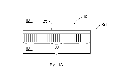
As is shown in Figs. 1-3, a bristled component 10 for a cosmetic applicator
includes a
longitudinal carrier 20 and a plurality of bristles 30. The carrier 20 and the
bristles 30 comprise
ultrasonically compatible materials. Such ultrasonically compatible materials
may include, e.g.,
CA 02952743 2016-12-15
WO 2015/200774
PCT/US2015/037937
nylon and polypropylene. The longitudinal carrier 20 has a longitudinal axis
21, a length L, and a
cross-section of any suitable shape. Non-limiting examples of the carrier's
cross-sectional shape
include round, rectangular, triangular, polygon, and elliptical shapes. The
carrier 20 may have an
irregular shape. The carrier 20 may also comprise a flat, solid, or hollow
structure. Figs. 29A-29Q
5 show several non-limiting exemplary embodiments of the cross-sectional
profile of the longitudinal
carrier 20. The carrier 20 can be made by any method known in the art, such
as, e.g., molding,
stamping, 3D printing, milling, extrusion, pultrusion, and any combination
thereof.
The carrier 20 may comprise a uniform, single-material structure.
Alternatively, the carrier
may comprise a multi-material structure, wherein at least one of the materials
is ultrasonically
10 wieldable. For example, the carrier 20 may comprise a side-by-side bi-
component structure (Figs.
31A-31G), wherein one of the materials (20a, 20b) is ultrasonically wieldable.
Alternatively, the
carrier 20 may comprise a so-called sheath-core structure (Figs. 32A and 32B),
wherein at least the
sheath 20a comprises an ultrasonically wieldable material. Such a sheath-core
carrier 20, wherein
one of the components (a core 20b) is fully surrounded by another component (a
sheath 20a), can be
15 beneficial when it is desirable to provide a core that contributes to
the overall strength of the carrier
20, while the sheath 20a enables carrier to be ultrasonically wielded to the
bristles.
Another type of the multi-component structure that may be used in construction
of the carrier
20 is a so-called matrix-fibril, or island-in-the-sea, bi-component structure,
Figs. 33A and 33B. In
such a carrier, there are non-continuous areas of one material ("fibrils" or
"islands") 20b disposed in
20 a matrix of another material ("sea") 20a. The "islands" 20b can comprise
a melt-spinnable polymer
such as, e.g., nylon, polyester, or polypropylene; and polystyrene water-
soluble polyesters and
plasticized or saponified polyvinyl alcohol can form the sea or matrix 20a.
Segmented pie
structures, comprising alternating portions of two or more materials, can be
also used as carrier 20,
Figs. 34A and 34B. In such a carrier, portions of alternating materials 20a,
20b can be made, e.g., of
nylon and polyester. In Fig. 34A, the carrier 20 comprises a so-called "hollow-
pie wedge"; and in
Fig. 34B, the carrier 20 comprises a so-called "conjugate-pie wedge."
Since the carrier 20 and the bristles 30 comprise ultrasonically compatible
materials, the
bristles 30 can be ultrasonically welded to the carrier 20 to form a
predetermined pattern of
distribution throughout the carrier's length L or any portion thereof. As a
result of the ultrasonic
welding, a direct bond 23 can be formed between a surface of the carrier 20
and lengthwise portions
of the bristles 30. The bristles 30, ultrasonically welded to the carrier 20,
can outwardly extend
CA 02952743 2016-12-15
WO 2015/200774
PCT/US2015/037937
16
from the carrier 20 according to a pre-determined pattern. Such a
predetermined pattern can be
based on the desired properties of the bristled component 10, as will be
discussed herein.
For example, the bristles 30 can extend from the carrier at various angles
comprising from
about ¨ 45 degrees to about + 45 degrees relative to the carrier's
longitudinal axis 21. All bristles 30
can have a common angle of inclination A relative to the axis 21.
Alternatively, the bristles 30 may
have differential angles of inclination relative to the axis 21. In the
embodiment of Fig. 2, for
example, all bristles 30 are inclined relative to the axis 21 at approximately
the same angle A. In the
embodiment of Fig. 3, the angles of inclination relative to the carrier 20
differ among the bristles 30,
and the angles at which the individual bristles 30 extend from the carrier are
such that some of the
bristles 30 mutually intersect to form crisscross patterns therebetween.
Bristles 30 may differ from
one another in at least one physical characteristic selected from the group
consisting of material,
length, thickness, shape, cross-sectional structure or geometry (e.g., solid
or hollow), specific
gravity, and angle of inclination relative to the carrier.
As is shown in Figs. 4A ¨ 5B, the plurality of bristles 30 can comprise at
least a first array or
row of bristles 31 and a second array or row of bristles 32. These arrays of
bristles 31 and 32 may
be disposed substantially parallel to one another (Figs. 4A and 4B).
Alternatively, the arrays of
bristles 31, 32 may be disposed to be not parallel to one another (Figs. 5A
and 5B). Within each of
the arrays of bristles, the individual bristles, too, may be parallel to one
another ¨ or, alternatively,
may not be parallel to one another.
In the embodiment of Fig. 9, the bristled in the first array of bristles 31
are grouped to
comprise a first plurality of tufts 41, while the bristles in the second array
of bristles 32 are grouped
to comprise a second plurality of tufts 42. The first plurality of tufts 41
can be offset relative to the
second plurality of tufts 42 along the length of the carrier 20. The extent of
the offset between the
tufts 41 of the first array of bristles 31 and the tufts 42 of the second
array of bristles 32 can be
constant throughout the length L of the carrier 20 or any portion thereof ¨ or
may vary, depending on
the application. In the exemplary embodiment of Fig. 9, the tufts 41 and 42
are offset at
approximately equal intervals relative to one another.
The elongated carrier 20 can have any suitable shape. In several exemplary
embodiments
shown herein, the elongated carrier 20 has a longitudinal slot 50 disposed
along the carrier's length
L, Fig 1B. The slot 50 can have any suitable shape. For example, the slot 50
can beneficially form a
CA 02952743 2016-12-15
WO 2015/200774
PCT/US2015/037937
17
generally V-shaped contour, as viewed in a cross-section perpendicular to the
longitudinal axis 21.
The V-shaped slot 50 has a first inner surface 51 and a second inner surface
52 angled relative to the
first inner surface, the first and second inner surfaces 51, 52 forming an
angle B therebetween. In
one embodiment, the angle B can comprise from about 1 degrees to about 179
degrees. In another
embodiment, the angle B can comprise from about 5 degrees to about 90 degrees.
In still another
embodiment, the angle B can comprise from about 10 degrees to about 45
degrees. In yet another
embodiment, the angle B can comprise from about 15 degrees to about 30
degrees.
The V-shaped slot 50 can be symmetrical, i.e., the first inner surface 51 and
the second inner
surface 52 have substantially equal depths D1, D2, as shown in Fig. 6.
Alternatively, the V-shaped
slot 50 can be asymmetrical, i.e., one of the inner surfaces 51, 52 can be
wider or narrower than the
other. In an exemplary embodiment of Figs. 1B, the first inner surface 51 of
the slot 50 is narrower
than the second inner surface 52 of the slot 50, while in the exemplary
embodiment of Fig. 7, the
first inner surface 51 (having the depth D1) is wider than the second inner
surface 52 (having the
depth D2).
The first and second inner surfaces 51, 52 of the slot 50 can conveniently
provide contact
surfaces to which the bristles 30 can be ultrasonically welded. For example,
the first array of bristles
31 can be ultrasonically welded to the first inner surface 51, while the
second array of bristles 32 can
be ultrasonically welded to the second inner surface 52, Fig. 7. The bristles
30 are welded to the
inner surfaces 51, 52 of the slot 50 such that lengthwise portions 35a of the
first array of bristles 31,
attached to the first inner surface 51, are substantially parallel to the
first inner surface 51; and
lengthwise portions 35b of the second array of bristles, attached to the
second inner surface 52, are
substantially parallel to the second inner surface 52 of the slot 50, Fig. 1B.
As used herein, the term
"lengthwise portion" of a bristle refers to the bristle's portion whose
dimension measured in the
longitudinal direction is significantly greater than the dimension measured in
the direction
perpendicular to the longitudinal direction.
In an embodiment comprising a plurality of arrays of bristles, the arrays of
bristles can
extend from the carrier 20 around its circumference, either equidistantly from
one another around the
carrier's circumference (Figs. 8, 10A-10D) ¨ or otherwise (Figs. 9, 10F, 10L,
10M). In an
exemplary embodiment shown in Fig. 8, comprising a plurality of arrays of
bristles 31, 32, 33, 34,
35, 36, and 37, circumferentially extending from the carrier 20, the arrays of
bristles are disposed
around the carrier in a non-random pattern wherein none of the arrays of
bristles has a corresponding
CA 02952743 2016-12-15
WO 2015/200774
PCT/US2015/037937
18
array of bristles disposed directly opposite thereto (across the longitudinal
carrier 20). The plurality
of arrays of bristles 30 may consist of either an odd number of arrays or even
number of arrays. The
odd number of bristles can be selected, e.g., from three, five, seven, nine,
eleven, thirteen, fifteen, et
cetera. Figs. 9-21 schematically show cross-sectional views of several non-
limiting exemplary
embodiments of the bristled component 10, comprising multiple arrays of
bristles 30 variously
distributed around the circumference of the bristled component 10.
The arrays of bristles 30 or individual bristles 30 can differ from one
another with respect to
one or more physical parameters or characteristics, such as, e.g., material,
color, length, thickness,
longitudinal shape, cross-sectional shape, specific gravity, rigidity,
stiffness, flexibility, elasticity,
number of individual bristles per a linear portion of the carrier, pattern of
distribution along the
carrier, density, surface characteristics (including surface energy), angles
of inclination of bristles
relative to the carrier, and angles of inclination of individual bristles
relative to one another.
The bristles 30 may have any suitable cross-sectional shape, including round,
rectangular,
triangular, polygon, elliptical, solid, hollow, and irregular shapes, and any
combination thereof.
Figs. 20A ¨ 20H show several exemplary embodiments of the above. The bristles
30 may be made
from monofilaments and composite filaments, such as, e.g., composite filament
comprising a core
and a shell. In an exemplary embodiment of the bristle 30 shown in Fig 21, the
bristle 30 includes a
shell 30 and a core 30b, the latter comprising three individual strands.
In one embodiment, the bristled component 10 may further comprise a core 60,
to which the
longitudinal carrier 20 is attached. In an exemplary embodiment of Fig. 22, a
fragment of the
bristled component 10 is shown as comprising a core 60 and a plurality of
longitudinal carriers 20.
The core 60 may comprise any suitable material, e.g., PET, Nylon,
Polypropylene, and others. The
core 60 may have any suitable cross-section, e.g., round, rectangular,
triangular, polygonal,
elliptical, solid, hollow, and irregular shapes (similar to those shown in
Figs. 20A ¨ 20H, without
regard to scale).
One skilled in the art would realize that the types of multi-component
structures, described
herein with respect to the carrier 20, can be utilized also for the
construction of the core 60; and any
suitable method of making the core 60 is contemplated by this disclosure,
e.g., molding, stamping,
3D printing, milling, extrusion, pultrusion, and any combination thereof.
CA 02952743 2016-12-15
WO 2015/200774
PCT/US2015/037937
19
Likewise, any suitable method of attaching the carrier 20 to the core 60 can
be in the process
disclosed herein, including, without limitation, those utilizing adhesive
materials, ultrasonic welding,
heat melting, as well as mechanical means, such as, e.g., those using
interlocking or sliding
protrusion and/or slots and the like.
The disclosure is also directed to a cosmetic applicator comprising the
bristled component, as
described herein. In several exemplary embodiments of Figs. 11-16, a cosmetic
applicator 200
comprises at least one stem 210 having a proximal end 211, including a handle
211a, a distal end
213 opposite to the proximal end 211, and a stem's surface 212. The bristled
component 10 can be
attached to the stem 210 according to various patterns. Alternatively or
additionally, the stem 210
can comprise the bristle component 10. In the latter configuration of the
applicator 200, the bristled
component-stem should beneficially possess suitable rigidity.
The cosmetic applicator 200 can utilize a single bristled component 10 that
can be designed
to perform one or more functional tasks. Alternatively the cosmetic applicator
200 can utilize a
plurality of bristle components 10, structured and configured to perform
various functional tasks,
such as, for example, heavy-loading mascara application, increased-volume
mascara application, lift-
and-curl mascara application, lash-separation mascara application, and any
combination thereof. As
one skilled in the art would recognize, the heavy-loading mascara application
involves accurately
loading the brush and controlling the product-loading profile on the brush to
provide for a heavy
load of product to be dispensed to the lashes. This is typically accomplished
by passing the loaded
brush through a wiping aperture significantly larger than the core of the
brush. The increased-
volume mascara application involves the ability of the brush to deposit
formula on the visible profile
of the lash in a way that gives the lashes a greater visual thickness or
diameter. Ideal applicators will
deliver heavy loading in a directed way without causing clumping of the lashes
together so that
individual lash volume is maximized. The lift-and-curl mascara application
involves the application
of mascara in such a way that the product helps to hold the lashes in a
groomed curled position or
enables the chemistry to set the lash shape in a curled position. Preferential
deposition of some
products may require more product depositions in the lower half of the lash
length to avoid the
weight of the product diminishing the curl effect through gravity. The lash-
separation mascara
application involves the ability for the user to comb and separate the lashes
while leaving the desired
distribution of the product on the lashes. Best separation applicators deposit
an even amount of the
CA 02952743 2016-12-15
WO 2015/200774
PCT/US2015/037937
product on each lash without grouping or bunching lashes together where they
might adhere to one
another as the product on some lashes bonds with the product on adjacent
lashes.
In the embodiment of Fig. 11, the bristled component 10 is attached to the
distal end 213 of
the stem 210 so that the bristled component 10 is substantially parallel to
the stem 210. The bristled
5
component 10 can be attached to the stem 210 either permanently or
removably. In the latter
instance, shown in Fig. 11, the stem 210 that is at least partially hollow,
and the bristled component
10 can be coupled to the stem 210 removably, e.g., through a frictional
connection, thread, a sliding
mechanism comprising mating / locking parts ¨ or otherwise by any means known
in the art.
In the embodiment of Fig. 12, the bristled component 10 is attached to the
stem 210 so that
10
the bristled component 10 can be angled relative to the stem 210. The angled
position of the bristled
component 10 can be permanent. Alternatively, the bristled component 10 can be
attached to the
stem 210 to be angularly movable relative thereto. Any means known in the art
can be used to
attach, either permanently or removably, the bristled component 10 to the
distal end of the stem 210
for angled configuration. For example, a hinge 213 or a similar rotational
connection, such as a ball
15
socket, can be utilized. A "living" hinge (not shown) can also be used to
position and/or adjust, as
may be desired, one portion of the bristled component 10 relative to the other
portion thereof, and
relative to the stem 210, in an angled configuration. The living hinge may be
particularly useful in
an embodiment of the bristled component 10 having the stem 120 comprising a
bendable wire (not
shown) that can be bent as desired.
20
In the embodiment of Fig. 13, several bristled components 10 are attached to
the stem 210
intermediate the stem's proximal and distal ends 211, 213 and in a parallel
configuration relative to
the stem 210. In such a configuration, the bristled component or components 10
can be permanently
affixed to the stem 210 by any means known in the art, for example by adhesive
gluing, ultrasonic
welding, and mechanical means. Alternatively, the bristled component or
components 10 can be
removably attached to the stem. In Fig. 17, e.g., the bristled components 10a,
10b, 10c, and 10d are
slidably attached to the stem 210 via grooves formed in the stem 210 and
correspondingly profiled
protrusions in the bristled components 10. In such or similar embodiment, one
bristled component
can be replaced with another bristled component that has different
functionality, or for the purposes
of testing or demonstration. This ability of the applicator 200 to removably
and interchangeably
receive various bristle components 10 contributes to the applicator's
increased versatility, for it
CA 02952743 2016-12-15
WO 2015/200774
PCT/US2015/037937
21
could allow a consumer to accomplish, with a single applicator, various
functional tasks, e.g., such
as those described herein above.
As is shown in Figs. 14 and 16, the bristled component 10 can be attached to
the stem 210 to
comprise a substantially helical coil spiraling around the stem's longitudinal
axis. This can be
accomplished by placing the bristled component 10 in a desired spiral
configuration around the stem
210 ¨ and attaching, either permanently or removably, the so placed bristled
component 10 to the
stem 210, Fig. 14. Alternatively or additionally, the bristled component 10
can be attached to the
stem 210 substantially parallel to the stem's longitudinal axis (Fig. 15) ¨
and then the stem 210,
together with the bristled component 10 attached thereto, can be twisted
around its own longitudinal
axis ¨ to cause the bristles 30, ultrasonically welded to the stem 210, to
change their position relative
to one another acquired during ultrasonic welding. In one specific embodiment,
illustrated in Fig.
16, the stem 210, together with the bristled component 10 attached thereto, is
being twisted around
its own longitudinal axis until the bristled component 10 acquires a desired
spiral shape (Fig. 16).
The elements of the disclosure, including the processes, described herein can
be used to
manufacture a personal-care applicator of any known design, including, without
limitation, a
conventional single-brush applicator, a dual-sided applicator, a roller
applicator, a so-called "clam-
shell" applicator, a so-called "tweezers" applicator, a applicator comprising
an unfolding brush, and
others. While the invention is not limited to the listed applicators, several
exemplary embodiments
of those are briefly described and illustrated herein.
An embodiment of the cosmetic applicator 300 shown in Fig. 39 includes a so-
called dual-
ended configuration, in which a handle 311 of the applicator is disposed
between the two ends of the
applicator, and wherein the applicator includes either at least one bristled
component 10 attached to
the stem 210 ¨ or the bristled component itself forms the stem 210, as is
described herein. Such a
dual-ended applicator 300 can accomplish a two-step product application, by
having two different
brushes at its opposite ends, e.g., a heavy-loading brush on one end and a
lift-and-curl brush on the
opposite end, or increased-volume brush on one end and a lash-separation brush
on the opposite end.
For this purpose, the dual-ended applicator may have, e.g., a molded brush or
a twisted-wire brush
on one end and an ultrasonically-welded brush on the opposing end.
Alternatively, two
ultrasonically-welded brushes in accordance with the present disclosure, and
having differential
physical properties, may be used in the dual-ended applicator.
CA 02952743 2016-12-15
WO 2015/200774
PCT/US2015/037937
22
Fig. 40 schematically shows an exemplary embodiment of a roller applicator
400, comprising
a cylindrical bristled roller 420 attached to a frame 430 for a rotational
movement within the frame
430. Any known means, such as, e.g., pins and ball bearings 410, can be used
to attach the roller
420. Either the entire functional surface, or any part thereof, of the roller
420 can comprise the
bristled component 10 of the invention. While the embodiment of the roller
applicator 400 shown in
Fig. 40 comprises plurality of individual bristles extending from the roll,
one skilled in the art would
readily appreciate that other embodiments, comprising, e.g., a felt-like
working surface instead of, or
in addition to, the individual bristles, can also be made in accordance with
the present disclosure.
An exemplary embodiment of a so-called "tweezers" applicator, shown in Figs.
41A and
41B, comprises a pair of legs interconnected at one of each of their
respective ends for relative
movement of the other of their respective ends, which are free. Fig 41A shows
the applicator 500 in
a folded position inside a case 530. At least one of those free ends can
comprise the bristled
component 10 of the invention. The two legs 510 of the applicator 500 can be
beneficially
interconnected for relative rotation by, e.g., a pin, a ball bearing, or any
other means known in the
art. The connection between the two legs 510 can be spring-loaded, as known in
the art. An
embodiment is contemplated (but not shown) in which the legs 510 are
permanently affixed to one
another, and their relative movement can be accomplished by flexing of one of
the legs relative to
the other.
One exemplary embodiment of an applicator 600 having a changing brush
configuration is
shown in Figs. 42A-42C. While two arrays of bristles 30 are shown in the
figures, the applicator
600 can comprise a plurality of arrays of bristles 30. These bristles 30 can
be structured to rotate or
otherwise move relative to one another ¨ to impart a desired functionality or
to accommodate a
shape of a holding case. In the embodiment shown, the bristles 30 are part of
the bristled component
10 that is structured and configured to fold and unfold, thereby changing the
brush's shape. The
brush can be designed to increase the density of the bristles 30 of the folded
brush relative to that of
the unfolded brush. It can be designed, e.g., to have the bristles 30 in the
adjacent arrays to be offset
in a longitudinal direction of the brush, so that the density in the fully
folded brush will double
relative to the density of the unfolded brush.
One permutation of the applicator 600 described above is shown in Figs. 42B
and 43C,
illustrating the folding brush in combination with a hollow stem 630. In this
embodiment, the
support 20 of the bristled component 10, can be moved inside the hollow stem
630, e.g., with a lever
CA 02952743 2016-12-15
WO 2015/200774
PCT/US2015/037937
23
650, from a fully folded position (Fig. 42B) to a fully unfolded position
(Fig. 42C). The hollow stem
630 can beneficially comprise gradually flaring sliding surfaces (not shown)
structured and
configured to facilitate folding and unfolding of the bristles 30.
Another embodiment of the applicator having a folding brush is schematically
shown in Figs.
43A and 43B. An applicator 700 comprises a hollow stem 730 and a lever 750
movable inside the
hollow stem 730. A pair of mutually opposite bristled components 10 can be
attached to one end of
the lever 750 for the combined movement inside the stem 730. The bristled
components 10 can be
spring-loaded or otherwise structured to rotate away from one another when the
lever 750 moves the
bristled components 10 out of the hollow stem 730. In the embodiment of Figs.
43A and 43B,
showing two bristled components 10, the bristled components 10 are positioned
to have their
respective bristles 30 extend in opposite directions when the brush is in the
folded position. One
skilled in the art will appreciate that the embodiment shown can also comprise
more than two
bristled components 10 structured and configured to unfold and fold as
principally explained herein.
Figs. 44A-44D schematically show exemplary embodiments of an applicator having
a
folding brush similar to that shown in Figs. 43A and 43B. In Figs. 44A, 44B,
and 44C, each of the
two bristled components 10 comprises a support 20 that has a semi-cylindrical
shape, specifically
shown in a cross-sectional view of Fig. 44C. In a folded position, these semi-
cylindrical supports 20
form a cylindrical shape. In Figs. 44A, 44B, and 44D, two bristled components
10 comprise a
substantially prismatic support 20 that has a triangular cross-sectional
shape, specifically shown in
Fig. 44D. In a folded position, these triangular supports 20 form a
rectangular or square cross-
section. One skilled in the art will readily appreciate that other cross-
sectional shapes of the support
can be utilized, if desired, including, without limitation, elliptical,
polygonal, irregular, and any
combination thereof.
As schematically shown in Figs. 23A-26, a basic continuous process for making
the bristled
component 10 can comprise several consecutive steps. A step of continuously
wrapping at least a
first strand of material or yarn 130 around a moving endless band 140 can be
conducted, e.g., at a
yarn-wrapping station 150. The band 140 has a top side 141, a backside 142,
and at least a first edge
143. In Fig. 23B, the band 140 also has a second edge 144. The strand of
material 130 can comprise
any suitable element, such as yarn, thread, monofilament, composite filament,
and the like. An
embodiment is contemplated in which the strand of material 130 comprises a
film. For convenience,
the terms "strand of material," "yarn," and the like, may be used herein
synonymously. The first
CA 02952743 2016-12-15
WO 2015/200774
PCT/US2015/037937
24
strand of material, or yarn, 130 may comprise any desired number of yarns,
e.g., two, three, four, et
cetera; these yarns may be identical ¨ or may differ from one another in one
or several physical
characteristics. Non-limiting examples of such physical characteristics
include yarn's material,
thickness, cross-sectional shape, surface energy, elasticity, rigidity, color,
and other characteristics or
parameters.
The yarn 130 can comprise any material suitable for ultrasonic welding to the
support strips
120. Unlimited examples of such a material include, e.g., nylon and polyester.
An embodiment is
contemplated in which the yarn 130 is made of a composite structure comprising
a material (or
materials) suitable for ultrasonic welding and a material (or materials) not
suitable for ultrasonic
welding. The first yarn 130 can be wound around the band 140 at a certain
controlled pace so that a
predetermined density of the yarn 130 can be achieved, particularly at the
point of the yarn's
juxtaposition with the first and second edges 143, 144. This density can be
constant ¨ or can vary
throughout the process, depending on the application. Any suitable method of
winding the yarn 130
around the band 140, known in the art, can be used.
In an embodiment incorporating several yarns 130, each of the yarns 130 can be
wound
around the band 140 according to its own pattern, including density, and an
angle of inclination C
relative to the direction D in which the band 140 is traveling, Fig. 23A. This
pattern with respect to
each yarn 130 may be identical to or may differ from the pattern or patterns
of the other yarns 130
being would around the band 140. The inclination angle C can be from + 45
degrees to ¨ 45
degrees. In the exemplary embodiment of Fig. 23A the angle C is approximately
90 degrees.
Alternatively, the yarn or yarns 130 can be wound at different densities
and/or angles C,
depending on the chosen design of the bristled component 10 being
manufactured. For example, in
an embodiment of Fig. 26, a first yarn 131 and a second yarn 132 are shown
wrapped around the
band 140 at differential angles. Relative to the band's longitudinal axis T
(i.e., the direction of the
band's movement), the resulting pattern of the yarns 131, 132 wrapped around
the band 140 will
comprise portions of the first yarn 131 and portions of the second yarn 132
disposed on the top side
141 of the band 140. The portions of the first yarn 131 disposed on the band's
top side 141 form a
first angle Cl relative to the band's longitudinal axis T, and the portions of
the second yarn 132
disposed on the band's top side 141 form a second angle C2 relative to the
direction of the band's
longitudinal axis T. In the exemplary embodiment of Fig. 26, the angles Cl and
C2 differ.
CA 02952743 2016-12-15
WO 2015/200774
PCT/US2015/037937
The process can further include a step of continuously juxtaposing a support
strip 120 with
the band 140 having the yarn or yarns 130 wound around. The support strip or
strips 120 can be
continuously or intermittently supplied by or through a strip-application
station 160, Fig. 23A. The
support strip 120 may have any suitable longitudinal and cross-sectional
shape, as described herein
5
in the context of the longitudinal support 20. The support strip 120 can be
made of any material
compatible with the material of the yarn 130 for the purposes of ultrasonic
welding therebetween.
An embodiment is contemplated in which the support strip 120 is made of a
composite structure
comprising a material (or materials) suitable for ultrasonic welding and a
material (or materials) not
suitable for ultrasonic welding. The support strip 120 has a longitudinal
welding surface structured
10
and configured to facilitate formation of an ultrasonic bond directly with
the yarn or yarns 130. One
embodiment of such a surface, comprising a V-shaped cross-sectional profile is
described herein in
the context of the longitudinal support 20.
In the exemplary embodiments of the process shown in Fig. 23B and Fig. 28, a
first support
strip 120a is juxtaposed with the first edge 143 of the band 140, and a second
support strip 120b is
15
juxtaposed with the second edge 144 of the band 140. In several exemplary
embodiments shown,
the first support strip 120a differs from the second support strip 120b, Figs.
23B, 28, and 30. But
one skilled in the art would readily understand that identical or similar
first and second support strips
120a, 120b can also be used. Also, an embodiment is contemplated in which only
one support strip
is used, Fig. 27.
20
The process further includes a step of ultrasonically welding the yarn 130
to the support strip
120, e.g., at a welding station 170, Fig. 23A. Several details of ultrasonic
welding, which can be
used in the process of the disclosure, are described in several patents listed
herein and incorporated
herein by reference. The ultrasonic welding involves, generally, an ultrasonic
horn and driver
fixtures (not shown). The ultrasonic welding can be performed at the
predetermined density or
25
densities of the yarn 130, which may be constant or varied, depending on the
application and the
design of the bristled component 10 being made. If desired, an angled
configuration, as viewed in
cross-section, of the bristles 30 relative to the carrier 20 in the bristled
component 10 being made can
be achieved by placing the support strip or strips 120 at an angle relative to
the band 140, Fig. 30.
During the ultrasonic welding, the lengthwise portions of the yarn 130
abutting the support
strip 120 and the band 140 in the area of its edge 143, can form a direct
ultrasonic bond 23 (Figs. 1B,
27 and 28) between the surface of the support strip 120 and the surfaces of
the lengthwise portions of
CA 02952743 2016-12-15
WO 2015/200774
PCT/US2015/037937
26
the yarn 120. In the continuous process, a continuous bristled strip or strips
110 can be formed,
comprising the support strip 120 and a plurality of yarn filaments 130
ultrasonically bonded to the
support strip 120 and outwardly extending therefrom. The plurality of yarn
filaments 130,
ultrasonically bonded to the strip 120 at the band's edge 143, may comprise
endless loops, Fig. 27.
Alternatively, the plurality of yarn filaments 130, ultrasonically bonded to
the strip 120, may have a
plurality of free ends 139, Fig. 28. The latter can be achieved by splitting
the yarn filaments 130, as
is described herein below.
The process may further comprise splitting the at least first yarn 130, e.g.,
at a splitting
station 180, thereby forming a plurality of free ends of the at least first
yarn 130, Fig. 23A. In an
embodiment of the process that utilizes first and second support strips 120a,
120b, the splitting of the
yarn 130 will result in the formation of first and second continuous bristled
strips 110a, 110b, each
comprising the support strip 120 and a plurality of yarn filaments 135
ultrasonically welded to and
extending from the support strips 120, Fig. 23A.
The process can further comprise a step of trimming or otherwise modifying the
plurality of
yarn filaments 135, e.g., at a modifying station 190, to cause the yarn
filaments 135 to acquire the
desired length, shape, surface characteristics, and other chosen physical
properties, thereby forming
finished bristles 30. Modification of yarn filaments may include, without
limitation, trimming,
coating, temperature treatment, chemical treatment, radiation treatment, as
well as changing of
surface energy, shape, color, angular orientation, and/or tip rounding. All or
a portion of the yarn
filaments 135 can be subjected to such a modification. In the exemplary
embodiment of the process
of Fig. 24, the step of modifying is shown to occur, at the modifying station
190, before the step of
cutting, at a cutting station 200, while in the exemplary embodiment of Fig.
25 this order is reversed.
The process can also include a step of modifying the at least first support
strip 120. The
support-strip modification can include, without limitation, trimming, coating,
temperature treatment,
chemical treatment, radiation treatment, modification of surface energy,
change of shape, and change
of color of at least a portion or portions of the support strip. For example,
the support strip 120 may
be selectively heated and/or partially grinded to form a desired shape
thereof. An embodiment is
contemplated in which the support strip 120 can be reinforces by addition of
another element or
material applied or affixed to the support strip 120.
CA 02952743 2016-12-15
WO 2015/200774
PCT/US2015/037937
27
The process may comprise a step of cutting the bristled strips 110, e.g., at a
cutting station
200, into a plurality of bristled components 10, each comprising a
longitudinal carrier 20 and a
plurality of bristles 30 ultrasonically welded thereto, Fig. 24. Any suitable
cutting tools can be
utilized, including, without limitation, blades, heat, chemical means, laser,
and others. The step of
cutting can be performed either prior to the step of modifying the plurality
of yarn filaments 110
(Fig. 25) or after the step modifying the plurality of yarn filaments 110
(Fig. 24), depending on the
application. Performing the step of modifying the plurality of yarn filaments
after the step of cutting
(Fig. 25) can enable a manufacturer to have a greater flexibility in creating
a variety of final
configurations of the bristled component 10. In an exemplary embodiment of
Fig. 25, for example,
the shown bristled components 10a differ from one another in their respective
bristle patterns, as do
the bristled components 10b.
Fig. 18 schematically shows several process steps comprising trimming the
bristle
components 10 (e.g., at the modifying station 190) to form trimmed bristled
components 10a, 10b,
10c; sorting the bristled components (e.g., at a sorting station 195); and
attaching the modified and
sorted bristle components 10a, 10b, 10c to the stems 210a, 210b, 210c,
respectively (e.g., at a stem-
applying station 197). Subsequently, a finishing step can be performed (e.g.,
at a finishing station
290), e.g., to supply the stem with a handle (211a, 211b, 211c), and/or
forming a desired angled
configuration of the stem, and the like ¨ to form the cosmetic applicator 200.
In an exemplary embodiment of the process shown in Fig. 19, the support strip
220 has
sufficient rigidity to form, after possible modification, the stem 210 of the
applicator. The support
strip 220 can be applied, similarly to the other embodiments of the process,
at the support-strip
application station 160. Thereafter, the support strip 220, juxtaposed with
the edges of the band 140,
can be ultrasonically welded, e.g., at the welding station 170, to the yarn
130. Then, the yarn 130
can be split, e.g., at the splitting station 180, into two continuous bristle
strips, which can
subsequently be cut, e.g., at the cutting station 200, into individual strips
100 of a desired length,
each comprising the support strip 220 and a plurality of yarn filaments 135
ultrasonically welded
thereto. These bristle strips 100 can be further modified, e.g., at the
modifying station 190, to form a
stem 210 out of the support strip 220. This can be done, e.g., by removing a
portion of the yarn
filaments 135 from the support strip 220. Such partial removal of the yarn
filaments 135 from the
support strip 220 can be accomplished by any known mechanical or chemical
means. In addition,
the yarn filaments 135 can be trimmed as well, to form a desired bristle-field
profile of the brush
CA 02952743 2016-12-15
WO 2015/200774
PCT/US2015/037937
28
being made. Finally, finishing steps can be done, such as, e.g., attaching a
handle 211a to the stem
210, and/or strengthening of the stem 210 (not shown).
One skilled in the art should realize that the depictions of the various
embodiments of the
process disclosed herein are exemplary embodiments describing principal and
optional steps of the
process ¨ and various permutations that may not be literally described herein,
including different
sequences or combinations of the process steps, are contemplated by the
present invention. For
example, the process may comprise the production of an array or multiplicity
of bristled components
10, preferably arranged in parallel rows to one another, affixed to a central
core component 11 that is
then attached, permanently or removably, to a distal end of an elongated stem
210 having a proximal
end including a handle 211a, as schematically shown in an exemplary embodiment
of Figs. 35A-
35C. In the embodiment of Fig. 22, a bristled component 10 comprises a core 60
and a plurality of
longitudinal bristle carriers 20 attached thereto, each bristle carrier having
a plurality of bristles 30
ultrasonically welded to the bristle carrier 20.
In exemplary embodiments schematically illustrated in Figs. 36A, 36B, and 36C,
the bristled
component 10 can be manufactured as comprising an essentially flat support
carrier 20 having a
plurality of bristles 30 extending therefrom according to a desired pattern
(Fig. 36A). Then, this
unfolded bristled component 10 can be folded around a core 60 to form any
desired cross-sectional
shape, e.g., a rectangular shape (Fig. 36B), or a round shape (Fig. 36C).
In another exemplary embodiment, schematically illustrated in Figs. 37A and
37B, the
bristled component 10 comprises two semi-cylinders, shown "unfolded" in Fig.
37A. These two
semi-cylinders can be united, at their mutually opposing edges, by a living
hinge 214 and folded to
abut one another, as shown in Fig. 37B. In yet another exemplary embodiment,
shown in Figs. 38A
¨ 38C, the bristles 30 can be ultrasonically welded to a continuous carrier
element 22 intermittently,
Fig. 38A. Then the carrier element 22, having bristles 30 welded thereto, can
be trimmed to form
multiple portions 22a of a desired length, Fig. 38B. After that, two portions
can be welded or
otherwise joined together to form the carrier 20 having a plurality of
bristles extending therefrom,
Fig. 38C.
While particular embodiments have been illustrated and described herein,
various other
changes and modifications may be made without departing from the spirit and
scope of the
invention. Moreover, although various aspects of the invention have been
described herein, such
CA 02952743 2016-12-15
WO 2015/200774
PCT/US2015/037937
29
aspects need not be utilized in combination. It is therefore intended to cover
in the appended claims
all such changes and modifications that are within the scope of the invention.
The terms "substantially," "essentially," "about," "approximately," and the
like, as may be
used herein, represent the inherent degree of uncertainty that may be
attributed to any quantitative
comparison, value, measurement, or other representation. These terms also
represent the degree by
which a quantitative representation may vary from a stated reference without
resulting in a change in
the basic function of the subject matter at issue. Further, the dimensions and
values disclosed herein
are not to be understood as being strictly limited to the exact numerical
values recited. Instead,
unless otherwise specified, each such dimension is intended to mean both the
recited value and a
functionally equivalent range surrounding that value. For example, values
disclosed as "65%" or "2
mm" are intended to mean "about 65%" or "about 2mm," respectively.
The disclosure of every document cited herein, including any cross-referenced
or related
patent or application and any patent application or patent to which this
application claims priority or
benefit thereof, is hereby incorporated herein by reference in its entirety
unless expressly excluded
or otherwise limited. The citation of any document is not an admission that it
is prior art with
respect to any invention disclosed or claimed herein ¨ or that it alone, or in
any combination with
any other reference or references, teaches, suggests, or discloses any such
invention. Further, to the
extent that any meaning or definition of a term in this document conflicts
with any meaning or
definition of the same or similar term in a document incorporated by
reference, the meaning or
definition assigned to that term in this document shall govern.