Note: Descriptions are shown in the official language in which they were submitted.
CA 02952939 2016-12-19
WO 2016/003659 PCT/US2015/036326
VARIABLE ANGLE LOCKING ROTATION CORRECTION PLATE
Fidd of the Invention
100011 The present invention generally relates to bone plates for the fixation
of fractures of the
hand and methods of coupling these plates to bone.
Background
[00021 Many current systems and methods for the fixation of fractures,
especially fractures in
the hand, are limited in the placement and orientation of plates over the
bone. For example, a
surgeon or other user may be required to select a final placement position of
the bone plate prior
to beginning a bone reduction procedure. Such plates may prevent the surgeon
from selecting the
most optimal implantation location for the bone plate. Furthermore, such
plates may prevent the
fixation of a fractured or otherwise damaged bone in a manner to fully correct
the alignment of
one or more bone fragments. Rather, such fragments must be brought as close to
a final
configuration as possible prior to the placement of the bone plate thereover,
which may result in
subsequent misalignment as the bone plate is being secured to the bone.
Rotational
misalignments are especially problematic due to crossing and scissoring of the
digits when a full
flexion of the fingers (e.g., making a fist) is attempted. Even minor
rotational errors in the
fingers may have to be surgically corrected after a fracture has healed.
Furthermore, this method
of insertion may also compromise adjacent soft tissue.
Summary of the Invention
10003J The present invention is directed to A bone plate sized and shaped for
fixation to one of a
phalangeal and metacarpal bone, comprising a head extending from a first end
to a second end
and having an elongated curved plate hole extending therethrough along a
curved path from a
first end to a second end, a plate hole axis of the elongated curved plate
hole extending
orthogonally from a top surface to a bone contacting surface of the bone plate
and a shaft
1
CA 02952939 2016-12-19
WO 2016/003659 PCT/US2015/036326
extending from the head, the shaft including an elongated shaft plate hole
extending therethrough
and elongated in a direction extending orthogonal to a central longitudinal
axis of the bone plate,
a plate hole axis of the elongated shaft plate hole extending orthogonally
from the top surface to
the bone contacting surface.
Brief Description of the Drawings
100041 Several embodiments of the invention will be described in the following
by way of
example and with reference to the accompanying drawings in which:
[00051 Fig. 1 shows a top view of a bone fixation plate according to a first
exemplary
embodiment of the invention;
Fig. 2 shows a bottom view of the bone fixation plate of Fig. I;
Fig. 3 shows a perspective view of the bone fixation plate of Fig. I; and
Fig. 4 shows a side view of the bone fixation plate of Fig. 1.
Detailed Description
[00061 The exemplary embodiments may be further understood with reference to
the following
description and the appended drawings, wherein like elements are referred to
with the same
reference numerals. The exemplary embodiments relate to apparatus and methods
for the
treatment of fractures and, in particular, to devices for fixing fractures of
the metacarpals and
phalanges. Exemplary embodiments describe a bone fixation plate having a bead
at a first end
with an elongated shaft extending therefrom to a second end. The head of the
exemplary bone
plate includes first and second variable angle fixation holes along a first
side thereof. The head
also includes an elongated curved hole extending along a second side thereof.
The elongated
curved hole permits rotation and angulation of the bone plate about a cortex
screw inserted
therethrough as will be described in more detail below. The shaft includes
third, fourth and fifth
plate holes staggered about a central longitudinal axis of the bone plate and
an elongated plate
hole extending along an axis orthogonal to the central longitudinal axis. As
will be described in
2
CA 02952939 2016-12-19
WO 2016/003659 PCT/US2015/036326
greater detail later on, the elongated hole further aids in optimally
positioning the plate over a
target portion of the bone. The shaft further may comprise sixth and seventh
variable angle
locking holes at a second end thereof. The sixth and seventh holes are aligned
with the central
longitudinal axis. A bone contacting surface of the head has a curvature
selected to conform to a
curvature of a dorsal surface of a bone to ensure flush seating of the plate
thereover. As will be
described in greater detail later on, the exemplary curved and elongated plate
holes permit the
adjustment of rotation and angulation of the bone plate prior to a final
fixation of the bone plate
to the bone.
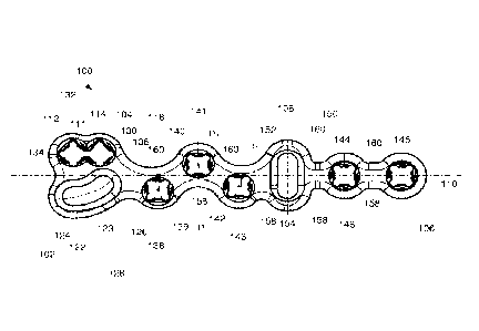
[0007} As shown in Figs. 1 - 4, an exemplary bone plate 100 has a head 104 at
a first end 102
thereof and a shaft 108 extending therefrom generally along a central
longitudinal axis 110 to a
second end 106. The head 102 is includes first and second variable angle plate
holes 112, 114
extending therethrough from a bone contacting surface 116 to an upper surface
118, the first and
second plate holes 112, 114 being open to one another at an opening 111.
Trajectories for plate
hole axes 113, 115 of the first and second plate holes 112, 114 are selected
to capture common
fracture patterns while avoiding the articular surface of the bone and
minimizing interference
with adjacent collateral ligaments. As shown in Fig. 4, the plate hole axes
113, 115 may be
generally orthogonal to the top surface 118 while the variable angle feature
of the plate holes
112, 114 permits a surgeon to vary an angle at which screws are inserted
through these holes
(relative to the hole axes) to optimize these trajectories to suit the anatomy
of a particular patient.
100081 The bead 104 further comprises an elongated curved plate hole 122
extending from a first
end 124 to a second end 126 along a curved arc-shaped axis 123. A length of
the plate hole 122
between the first and second ends 124, 126 is greater than a diameter of the
first and second plate
holes 112, 114. A width of the plate hole 122 is equivalent to a diameter of
the first and second
plate holes 112, 114. A length of the plate hole 122 may be equivalent to or
slightly longer than
a length of a combination of the first and second plate plates holes 112, 114.
The first and
second plate holes 112, 114 and the curved plate hole 122 may be sized, shaped
and positioned
3
CA 02952939 2016-12-19
WO 2016/003659 PCT/US2015/036326
along the head 104 to maximize the amount of area for screw placement while
minimizing the
foot print of the head 104 and maintaining strength of the plate 100.
[00091 A radius of curvature of the plate hole 122 may be, for example, 3.75
mm or 5.0 mm,
although other values are depicted within the scope of the invention. A center
from which the
radius of curvature of the plate hole 122 may be measured may be located
through, for example,
the first plate hole 112. The curved plate hole 122 follows a banana-like
curvature, curving
toward the central longitudinal axis 110 so that the first end 124 is further
from the axis 110 than
is the second end 126. The exemplary curvature of the elongated curved plate
hole 122 permits
the bone plate slid along the curve about a bone screw inserted therethrough.
Specifically, the
bone screw (not shown) may be inserted into the elongated curved plate hole
122 at a position
selected to capture one or more bone fragments. The bone screw (not screw) may
be inserted
through the bone plate 100 and bone (not shown) to a first depth permitting
the bone plate 100 to
be movable about the bone screw. Subsequent sliding of the bone plate 100
along the axis 123
moves the bone plate 100 along a curved path corresponding to the path 123 as
the bone plate
100 is moved in first and second directions along the central longitudinal
axis 110. Furthermore,
a surgeon or other user may rotate the bone plate 100 about the bone screw
(not shown) received
in the elongated plate hole 122 to achieve a desired orientation over the
bone, as will be
described in greater detail with respect to the exemplary method below. As
phalange and
metacarpal fractures typically result in a breakage of the Ahead or Acondyle@
to a smaller
fragment, the curved plate hole 122 located in the head 104 permits the
surgeon or other user to
affix the head 104 of the plate 100 to that smaller fragment first, and then
would have the ability
to rotate the plate to fit the shaft.
100101 An outer surface of the head 104 substantially follows a position of
the first, second and
elongated plate holes 112, 114, 122. Specifically, a first side wall of the
head 128 of the head
104 follows a curved path corresponding to a curvature of the elongated plate
hole 122. A
second side wall 130 of the head 104 is also curved to conform to the shape of
the first and
4
CA 02952939 2016-12-19
WO 2016/003659 PCT/US2015/036326
second plate holes 112, 114, the size and curvature of the second wall 130
being formed so that a
minimum clearance is formed about the first and second plate hole 112, 114. A
first notch 132 is
formed on the second side wall 130 of the head 104 and has a substantially
rounded shape. The
first notch 132 is formed as a cutout extending into the second side wall 130
and has a shape
corresponding to an arc of a circle. In another embodiment, the first notch
132 may have a non-
circular shape (e.g., oblong, etc.) without deviating from the scope of the
invention. The first
end 102 of the bone plate 100 also comprises a second notch 134 positioned
between the first
and elongated plate holes 112, 122, the second notch 134 also having a
substantially rounded
shape. In one embodiment, the second notch 134 has a radius of curvature of
1.5 mm or 2.0 min.
However, this radius of curvature is exemplary only and other values may be
used without
deviating from the scope of the invention. The second notch 134 is centered
with respect to the
central longitudinal axis 110 of the bone plate. In another embodiment, the
second notch 134
may have a non-circular shape (e.g., oblong, etc.) without deviating from the
scope of the
invention. The first and second notches 132, 134 also effectively reduce an
outer profile of the
bone plate 100 without compromising the structural integrity thereof.
100111 The hone-contacting surface 116 of the bone plate 100 is curved to
conform to the
curvature of a target dorsal surface of a metacarpal or phalangeal bone. In
one embodiment, the
bone-contacting surface 116 of the head 104 includes curvatures of varying
radii. A
predetermined length of the head 104 at the first corner 122 may be curved
downward toward the
bone in a direction toward a palmar surface of the bone in an implanted
configuration. This
downward curvature aids in reduction of the fracture.
[0012} A reduced diameter neck 136 separates the head 104 from the shaft 108.
The shaft 108
extends distally from the neck 136 to the distal end 106 and includes third,
fourth, fifth, sixth and
seventh variable angle plate holes 138, 140, 142, 144, 146. In one embodiment,
trajectories 139,
141, 143, 145, 147 of the third, fourth, fifth, sixth and seventh place holes
138, 140, 142, 144,
146 are orthogonal to a plane housing the bone plate 100 while the variable
angle features
CA 02952939 2016-12-19
WO 2016/003659 PCT/US2015/036326
thereof permit a surgeon to vary the angles at which screws are inserted
therethrough to optimize
these trajectories to suit the anatomy of a particular patient. Thus, the
trajectories 139, 141, 143,
145, 147 may assume any path selected to lockingly engage the bone without
extending through
an opposing cortical surface thereof. The third, fourth and fifth plate holes
138, 140, 142 are
staggered about the central longitudinal axis 110 so that central axes 139,
141, 143 thereof are
offset relative to the axis 110. The staggered shaft portion of the plate 100
increases plate
strength and allows for distribution of bone screws over a larger surface area
of the bone to
capture fracture fragments in a comminuted shaft, as those skilled in the art
will understand.
Specifically, the third and fifth plate holes 138, 142 are offset in a first
direction toward a first
side wall 148 of the shaft 108. Specifically, the third and fifth plate holes
138, 142 extend away
from the axis 110 in the first direction by a distance greater than any other
portion of the shaft
108. In a preferred embodiment, the central axis 139 of the third plate hole
138 is separated
from the axis 110 by a distance Di and the central axis 143 of the fifth plate
hole 142 is separated
from the axis 110 by a distance D2, wherein DI is greater than D2. The fourth
plate hole 140 is
offset in a second direction toward a second side wall 150 of the shaft 108 so
that a distance D3
is formed between a central axis 141 of the fourth plate hole 140 and the axis
110. The distances
D2 and D3 may be substantially equivalent to one another. The central axes
141, 143 of the
fourth and fifth plates holes 140, 142, respectively, may be closer to the
axis 110 than the central
axis 139 of the third plate hoe 138 since the phalanges and metacarpals become
thinner towards
a central portion thereof. It will be understood by those of skill in the art,
however, that DI is not
required to be greater than D2 and D3, so long as the third, fourth and fifth
holes 138, 140, 142
are positioned through the plate 100 so that, when the plate 100 is positioned
along a bone, the
third, fourth and fifth holes 138, 140, 142 extend along a portion of the
bone. It will also be
understood by those of skill in the art that although the exemplary embodiment
shows the third
and fifth holes 138, 142 as offset from the axis 110 in the first direction
towards the first side
wall 148 and the fourth plate hole 140 is offset from the axis 110 in the
second direction toward
the second side wall 150, a direction in which the third, fourth and fifth
holes 138, 140, 142 are
offset may also be reversed. In particular, the third and fifth holes 138, 142
may be offset in the
6
CA 02952939 2016-12-19
WO 2016/003659 PCT/US2015/036326
second direction while the fourth hole 140 may be offset in the first
direction.
[00131 The shaft 108 also includes an elongated hole 152 elongated in a
direction orthogonal to
the longitudinal axis 110. The elongated hole 152 is centered about the
central longitudinal axis
110, a trajectory 153 thereof extending orthogonally from the bone contacting
surface 116 to the
top surface 118. An axial length of the elongated hole 130 is at least larger
than a diameter of
the first through seventh plate holes 112, 114, 138, 140, 142, 144, 146 while
a width of the
elongated hole 152 may be equivalent to the diameter of first through seventh
plate holes 112,
114, 138, 140, 142, 144, 146. In a preferred embodiment, the first through
seventh plate holes
112, 114, 138, 140, 142, 144, 146 are 1.5 mm variable angle holes. However, in
another
embodiment, one or more of the first through seventh plate holes 112, 114,
138, 140, 142, 144,
146 may be formed as standard locking holes having a diameter of 2.0 mm. Still
further, it is
noted that any other diameter of the holes may be used without deviating from
the scope of the
invention to conform to the requirements of a particular procedure. As will be
described in
greater detail below with respect to the exemplary method, the elongated hole
130 permits a
surgeon or other user to slide the bone plate 100 over the bone within a
predetermined range
(i.e., corresponding to a length of the elongated hole 152) prior to locking
the bone plate 100 in
place. In one embodiment, the elongated hole 130 may allow for a movement of
the bone plate
along an axis 154 while also permitting rotation of the bone plate 100
therearound. Specifically,
a surgeon or other user may insert a first bone screw into one of the
elongated holes 122, 152 to
affect a position of the bone plate 100 over the bone, as will also be
described in greater detail
later. The exemplary elongated plate hole 152 extends orthogonally through the
bone plate from
the upper surface 118 to the bone contacting surface 116. The elongated holes
122, 152 bypass
the need for a guidewire to position the bone plate 100 over the bone. Rather,
since the bone
plate 100 is adjustable relative to a bone screw inserted through the
elongated hole 122, 152, a
surgeon or other user may use the elongated holes 122, 152 as a guide when
positioning the bone
plate 100 over the bone.
7
CA 02952939 2016-12-19
WO 2016/003659 PCT/US2015/036326
100141 The sixth and seventh holes 144, 146 are axially aligned and
symmetrically positioned
relative to the central longitudinal axis 110.
100151 The hone-contacting surface 116 of the shaft 108 is curved along the
longitudinal axis
110 to conform to the substantially cylindrical shape of the target portion of
the bone over which
the shaft 108 will be seated. In one embodiment, the length of the shaft 108
may include a single
uniform curvature. In another embodiment, the bone contacting surface 116 of
the shaft 108
may include a plurality of curves selected to ensure that the shaft 108 is
seated flush over the
bone.
[00161 The shaft 108 also includes a plurality of first webbed portions 158
extending along the
first side wall 148 between each of the holes 138, 142, 148, 144, 146 and a
plurality of second
webbed portions 160 extending along the second side wall 150 between each of
the holes 114,
140, 152, 144, 146. The first and second webbed portions 158, 160 are formed
as notches
extending into the width of the bone plate 100 reducing a profile thereof
while maintaining the
structural integrity of the bone plate 100. The first and second webbed
portions 158, 160 as well
as the first and second notches 132, 134 are sized to maintain a minimum
desired clearance
remains around the boundary of each of the plate boles of the bone plate 100.
An outer
periphery of the bone plate 100 may include a rounded taper to further reduce
the profile as
would be understood by those skilled in the art.
[0017] The bon-contacting surface 116 of the bone plate further comprises a
plurality of
undercuts 162, 164, 166, 168, 170, 172 positioned between plate holes to
permit bone ingrowth
while also imparting additional flexibility to the bone plate 100 to permit a
surgeon to further
bend the bone plate 100 to a desired curvature to more closely match the
anatomy of a patient=s
bone and promote healthier bone ingrowth. The undercuts 162, 164, 166, 168,
170, 172 are
formed as cutouts extending into the bone plate 100 from the bone-contacting
surface 116 by a
depth smaller than a thickness of the bone plate 100. In a preferred
embodiment, a shape of the
CA 02952939 2016-12-19
WO 2016/003659 PCT/US2015/036326
cutouts is a half-cylindrical segment, although other shapes (e.g.,
rectangular, etc.) may be used
without deviating from the scope of the invention. First, second and third
undercuts 162, 164,
166 are angled with respect to the axis 110 to in accordance with a position
of the third, fourth
and fifth plate holes 138, 140, 142. Specifically, the first undercut 162
encloses an angle of 105E
relative to the axis 110. The second undercut 164 encloses an angle of 60E
relative to the axis
110. The third undercut 166 encloses an angle of 120E relative to the axis
110. Fourth, fifth and
sixth undercuts 168, 170, 172 extend orthogonal to the axis 110.
[0018] The exemplary bone plate 100 is configured for use in indirect
reduction techniques for
crushes, multi-fragmented and/or periarticular fractures of the metacarpals
and phalanges. In
accordance with an exemplary method according to the invention, the bone plate
100 is
positioned over a target dorsal surface of a bone 10 in a target orientation
so that the elongated
curved plate hole 112 is positioned adjacent a far side of a fracture near a
section of intact bone.
The surgeon or other user approximates the desired position of the bone plate
100 over the bone
10. A first cortex screw (not shown) is then inserted through the elongated
curved hole 122 and
into the bone 10 to a first depth sufficient to hold the bone plate 100 over
the bone 10 while still
permitting movement of the bone plate 100 relative to the bone 10. The bone
plate 100 is then
slid along the axis 123 about the first cortex screw (not shown) received in
the hole 122 until a
desired position has been reached. The first cortex screw (not shown) may be
tightened and
loosened a plurality of times during this repositioning. A second cortex screw
(not shown) is
then inserted into the elongated bole 152 to the first depth sufficient to
hold the bone plate 100
over the bone 10 while still permitting movement of the bone plate 100
relative to the bone 10.
The bone plate 100 is then repositioned along the axis 154 to a desired final
configuration. The
first and second cortex screw (not shown) may be tightened and loosened a
plurality of times
during the above repositioning. The exemplary bone plate 100 according to the
invention allows
for an adjustment of rotation and angulation of the bone plate 100 prior to a
permanent fixation
thereof over the bone. Once the target position has been reached, additional
screws (not shown)
may be inserted into any of the remaining plate holes 112, 114, 138, 140, 142,
144, 146. The
9
CA 02952939 2016-12-19
WO 2016/003659 PCT/US2015/036326
exemplary system and method according to the invention bypasses the need for
pre-drilling holes
in the bone. Rather, once the target position has been achieved, bore holes
are drilled through
any of the plate holes 112, 114, 138, 140, 142, 144, 146 and into the bone 10
at a desired angle
selected to conform to the requirements of the particular bone. in contrast,
present bone fixation
systems require the insertion of a guidewire into the bone prior to the
placement of the bone
plate over the bone, thus requiring that a final position of the bone plate
100 be selected prior to
the placement of the bone plate over the bone. This method may lead to reduced
accuracy in
placement, especially in the fixation of phalangeal bones where even the
smallest deviation,
(e.g., in millimeters) from a correct position may lead to less than optimum
fixation. The
exemplary bone plate 100, on the other hand, permits adjustment of the
position of the bone plate
100 even after the bone plate 100 has been initially secured to the bone,
thereby ensuring that the
final position of the bone plate 100 captures all fragments of the bone 10
while avoiding
interference with ligaments, tendons or other tissue.
100,19i It will be appreciated by those skilled in the art that various
modifications and alterations
of the disclosed embodiments may be made without departing from the broad
scope of the
invention. Some of these have been discussed above and others will be apparent
to those skilled
in the art.