Note: Descriptions are shown in the official language in which they were submitted.
CA 02953377 2017-01-03
LOCKING DEVICE FOR WASTE CONTAINER
FIELD OF THE INVENTION
[0001] The present invention generally relates to locking devices,
particularly for waste
containers. In particular, the invention relates to waste container locking
devices that are
actuated by gravity.
BACKGROUND
[0002] As is well known, waste containers, such as refuse dumpsters for use in
residential and
industrial applications, typically include a container supported on a base
structure. With the
advent of mechanized trash removal, there have been created a number of large
sized trash bins
or dumpster containers. These containers usually comprise a block-shaped or
pyramid-shaped
container with a hinged lid attached to one side thereof. The container
further includes
attachments for accommodating various forked lifting mechanisms of the trash
removal vehicle.
The containers are lifted by the lifting mechanism of the trash removal
vehicle and pivoted in
some fashion so that the hinged top of the container opens and the trash
contained therein is
emptied into the vehicle. The container is then returned to a position on the
ground, and the
hinged lid closes on top of the container. Frequently these large trash
receptacles are rented from
a trash removal service. These receptacles are not provided free of charge,
and consequently their
frequent emptying and service can become a considerable expense. This expense
is increased
when unauthorized users of the receptacle freely deposit trash therein. This
unauthorized use
necessitates a more frequent emptying of the container, and of course the
unauthorized user does
not contribute to offset the increased expense.
1
CA 02953377 2017-01-03
[0003] In order to reduce the added expense that comes from unauthorized use,
the dumpsters
frequently are locked. While conventional chains and padlocks reduce
unauthorized dumpster
use, they also add to operating expenses because the driver of the truck
emptying the dumpster
must get out of the truck to unlock the padlock on the dumpster. In the early
1990's, companies
began the development and marketing of dumpster locking mechanisms that opened
automatically when the dumpster was lifted and inverted to dump the trash into
the truck. With
such an automatic lock, the driver is not required to leave the truck which
saves the trash
company hundreds of dollars each year.
[0004] Conventional automatic locks may be bulky, expensive and difficult to
mount to multiple
containers. Since containers come in a variety of shapes and sizes, it is
important that the
locking device be sized and shaped to be retrofit onto a variety of existing
containers. Moreover,
the locking device must be able to withstand the rigors of everyday, outdoor
use in the waste
environment.
[0005] Therefore, there exists a need for an automatic locking device that
improves upon prior
automatic locking devices and solves the problems inherent in known automatic
locking devices.
2
CA 02953377 2017-01-03
SUMMARY OF THE INVENTION
[0006] The present invention relates to a gravity actuated locking device for
a waste container,
preferably a waste dumpster. The container has a hinged lid that is movable
between an upright
storing position and a tilted dumping position for emptying the container. The
locking device
allows the lid of the container, when the container is in an upright position,
to be locked to
prevent unauthorized access to the container. When the container is tilted
from the upright
position, e.g. to empty the contents of the container, the locking device
allows the lid to open.
[0007] The locking device is designed to be fixed to the container and
contains a gravity
operated locking mechanism and a locking unit that couples the gravity
operated locking
mechanism to a locking bar. The locking bar allows the lid of the container to
be blocked or
opened depending upon the relative position of the locking bar to the lid. In
the blocked
position, the locking bar sits over the lid and does not allow it to be
opened. In the opened
position, the locking bar is removed from blocking the lid and allows the lid
to be opened. The
gravity operated locking mechanism is housed inside a base unit that is
adapted to be fixed to the
container. The gravity operated locking mechanism contains a pair of stop
members, a sliding
platform sandwiched and slidable between the pair of stop members, a rolling
member disposed
within a slanted slot in the sliding platform, a spring member biasing the
sliding platform toward
a blocked position, and a cam member which is rotatable to bias the sliding
platform in an
opened position opposing the blocked position. When the container is in the
upright position, the
rolling member, due to its position in the slanted slot, and the stop members
cooperate to block
the sliding platform from being moved against the force of the spring member.
However, when
the container is tilted forward, e.g. for emptying the contents of the
container, the rolling member
is pulled by gravity to an opened position in the slanted slot which releases
the block on the
3
CA 02953377 2017-01-03
sliding platform. In that opened position, the sliding platform can be pushed
forward against the
spring member by rotation of the cam member, which thereby allows the locking
unit to rotate to
release the lid of the container.
[0008] Further areas of applicability of the present invention will become
apparent from the
detailed description provided hereinafter. It should be understood that the
detailed description
and specific examples, while indicating the preferred embodiment of the
invention, are intended
for purposes of illustration only and are not intended to limit the scope of
the invention.
4
CA 02953377 2017-01-03
BRIEF DESCRIPTION OF THE DRAWINGS
[0009] The foregoing background and summary, as well as the following detailed
description of
the drawings, will be better understood when read in conjunction with the
appended drawings.
For the purpose of illustrating the invention, there is shown in the drawings
embodiments which
are presently preferred. It should be understood, however, that the invention
is not limited to the
precise arrangements and instrumentalities shown. In the drawings:
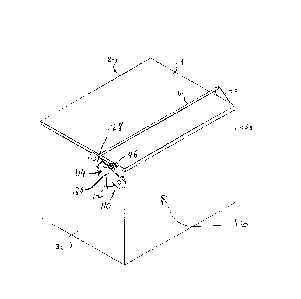
[0010] FIG. 1 is a perspective view of a waste container in an upright
position with a locking
device according to an exemplary embodiment of the present invention shown in
a closed
position;
[0011] FIG. 2 is a perspective view of the waste container in a tilted
position with the locking
device according to the exemplary embodiment of the present invention shown in
an open
position;
[0012] FIG. 3 is a side elevational view of a waste container in an upright
position with a locking
device according to the exemplary embodiment of the present invention shown in
a closed
position;
[0013] FIG. 4 is a side view of the waste container of FIG. 3 in an upright
position with the
locking device according to the exemplary embodiment of the present invention,
shown without
the padlock and with a pivotable unit separated from a fixed unit;
[0014] FIG. 5 is a side elevational view of the locking device according to
the exemplary
embodiment of the present invention shown in the closed position;
[0015] FIG. 6 is a side elevational view of the locking device of FIG. 5 shown
without the
padlock and with the pivotable unit separated from the rest of the locking
device;
CA 02953377 2017-01-03
[0016] FIGS. 7A and 7B show a perspective view and an assembly view,
respectively, of the
locking device according to the exemplary embodiment of the present invention
in a blocking
position, without a base plate and the outer plate (FIG. 7A shows the
assembled locking device,
while FIG. 7B shows the parts separated);
[0017] FIG. 8 is a top view of the locking device according to the exemplary
embodiment of the
present invention in the blocked position;
[0018] FIGS. 9A and 9B show side views of the of the locking device according
to the
exemplary embodiment of the present invention in the blocked position (FIG. 9A
shows the view
with the front stop member removed, while FIG. 9B shows the view with the
front stop member
in place); and
[0019] FIGS. 10A and 10 B show side views of the locking device according to
the exemplary
embodiment of the present invention in the opened position (FIG. 10A shows the
view with the
front stop member removed, while FIG. 10B shows the view with the front stop
member in
place).
6
CA 02953377 2017-01-03
DETAILED DESCRIPTION OF THE PREFERRED EMBODIMENT(S)
[0020] The exemplary embodiment of the present invention will now be described
with the
reference to accompanying drawings. The following description of the preferred
embodiment is
merely exemplary in nature and is in no way intended to limit the invention,
its application, or
uses.
[0021] For purposes of the following description, certain terminology is used
in the following
description for convenience only and is not limiting. The characterizations of
various
components and orientations described herein as being "vertical",
"horizontal", "upright", "right",
"left", "side", "top", or "bottom" designate directions in the drawings to
which reference is made
and are relative characterizations only based upon the particular position or
orientation of a given
component as illustrated. These terms shall not be regarded as limiting the
invention. The words
"downward" and "upward" refer to position in a vertical direction relative to
a geometric center
of the apparatus of the present invention and designated parts thereof. The
terminology includes
the words above specifically mentioned, derivatives thereof and words of
similar import.
Additionally, the word "a" as used in the claims means "at least one."
[0022] FIGS. 1 and 2 illustrate a waste or storage container 2, such as a
trash collector or
dumpster. The container 2, as best illustrated in FIGS. 1 and 2, is preferably
an industrial-type
dumpster used for retaining, storing, and eventually disposing of refuse
(waste), such as glass
fragments produced during the manufacture of automotive glass and other
industrial waste
products. The container 2 may be tilted or otherwise pivoted from an upright
storage position
(wherein the waste container 2 is sitting generally horizontally) (shown in
FIG. 1) to a tilted or
dumping position (shown in FIG. 2).
7
CA 02953377 2017-01-03
[0023] The container 2 has at least one hinged lid 4 on top of a main box 16,
a safety locking
device 110 according to an exemplary embodiment of the present invention, and
a locking bar 6
extending across the width of the container 2 (FIGS. 1 and 2). The locking
device 110 is
provided for locking and unlocking the waste container 2 to prevent the
inadvertent dumping of
its contents or unauthorized opening of the lid 4. The locking bar 6 extends
between a pivotable
unit 128, as best shown in FIG. 5, of the safety locking device 110 at one end
and a pivoting bar
8 at the other end thereof, as best shown in FIG. 1. The pivotable unit 128 is
part of the safety
locking device 110 which is mounted to a side wall 3b of the container 2, such
as the left side
wall as shown in FIG. 5, while the pivoting bar 8 is pivotally fixed to a side
wall 3a (opposing
and approximately parallel to the left side wall 3b) of the container 2. When
the locking bar 6 is
located over the lid 4, it blocks the lid 4 and prevents lid 4 from being
opened. When locking bar
6 is rotated forward during dumping of container 2, toward to the front of the
container 2 and
away from the lid 4, the lid 4 can be opened to allow for emptying or filling
of the container 2.
Rotation of the locking bar 6 away from the lid 4 can be effected by pulling
on the locking bar 6
to allow the pivoting bar 8 and pivotable unit 128 to pivot at their
respective attachments to the
side walls 3a, 3b, thereby allowing the locking bar 6 to move away from the
lid 4 of the
container 2. The pivotable unit 128 is part of the safety locking device 110
and is pivotally
coupled to the base unit 112. When a padlock 46 or the like is used to couple
the pivotable unit
128 to the rest of the locking device 110, the first pivotable unit 128 cannot
pivot and locks
locking bar 6 in place. However, when the lock 46 is removed, the pivotable
unit 128 pivots
freely and the locking bar 6 can be moved to allow the lid 4 to be opened.
[0024] Even when the lock 46 is in place, the safety locking device 110 is a
gravity-actuated
device that allows the locking bar 6 to be moved to allow for the lid 4 to
open, such as when the
8
CA 02953377 2017-01-03
container 2 is tilted to the dumping position (FIG. 2). When the container 2
is in its upright
position of FIG. 1 and when the lock 46 is in place, the locking device 110
prevents opening of
the lid 4 by keeping the locking bar 6 in place. To open the lid 4, a user
must first remove the
lock 46 to uncouple the pivotable unit 128 from the rest of the locking device
110, then pull the
locking bar 6 forward to unblock the lid 4. Unauthorized use of the container
2 is thus
prevented, while allowing for emptying of the container 2 by tilting it, e.g.,
into a trash truck.
[0025] FIGS. 3-10 illustrate an exemplary embodiment of a safety locking
device for a waste or
storage container 2, generally depicted by the reference character 110. The
locking device 110
according to an exemplary embodiment of the present invention, as illustrated
in detail in FIGS.
3-6, comprises a base unit (housing) 112 to be fixed to the left side wall 3b
of the waste container
2, and an elongated pivotable unit 128 pivotally mounted to the base unit 112
for pivotable
movement relative to the base unit 112 about a pivot axis 115 as best shown in
FIGS. 7-8. The
locking bar 6 is secured to the pivotable unit 128 at a distal end thereof so
as to extend across the
length of the waste container 2, as best illustrated in FIGS. 1-2. The
pivotable unit 128, the
pivoting bar 8 and the locking bar 6 movable therewith are able to translate
from a closed
position of the waste container 2 wherein the locking bar 6 extends over the
hinged lid 4 of the
waste container 2 so as to prevent opening of the waste container 2, as
illustrated in FIGS. 3 and
5, and an open position of the waste container 2 wherein the locking bar 6 is
horizontally spaced
away from the hinged lid 4 of the waste container 2 so as to allow the opening
of the hinged lid 4
of the waste container 2, as illustrated in FIGS. 4 and 6.
[0026] The base unit 112, as illustrated in detail in FIGS. 7-8, comprises a
base member 124
having a U-shaped cross-section (as best shown in FIG. 7B) and defining an
open, elongated,
channel-like cavity 125, a base plate 126 (shown in FIG. 8) non-movably
attached to a bottom of
9
CA 02953377 2017-01-03
the base member 124, such as by welding, in order to cover the cavity 125, and
two oppositely
disposed L-shaped mounting members 116 fixed to the base member 124 at
longitudinally
opposite ends thereof, such as by welding. The oppositely disposed mounting
members 116
delimit the cavity 125 within the base unit 112. Each of the mounting members
116 has a
through-hole 117 therethrough. Accordingly, the base unit 112 may be fastened
to the left side
wall 3b of the waste container 2 by threaded fasteners (not shown in detail)
extending through
holes 117 in the mounting members 116. The base plate 126, as best shown in
FIG. 8, is adjacent
to the left side wall 3b of the waste container 2 when the locking device 110
is mounted to the
waste container 2.
[0027] The base unit 112 further comprises a pivoting, gravity operated
locking mechanism 136
disposed in the cavity 125 of the base member 124. The locking mechanism 136
comprises a pair
of stop members 138 disposed in the cavity 125 of the base member 124 and
extending between
the mounting members 116, a sliding platform 142 movable within the cavity 125
between an
opened and a blocked positions ("opened position" refers to the position of
the locking device
110 that allows the lid 4 to open; "blocked position" refers to the position
of the locking device
110 that allows the lid 4 to be blocked by the locking bar 6), a rolling
member 140 disposed
within the cavity 125 of the base member 124 and moveable under gravity
relative to the stop
members 138 and the sliding platform 142, a spring member 152 biasing the
sliding platform 142
toward the blocked position, and a cam member 118. The sliding platform 142 is
sandwiched
between the stop members 138 and is reciprocatingly and slidingly movable
within the cavity
125 relative to the stop members 138 between the opposite mounting members 116
and
substantially perpendicular to the pivot axis 115. The sliding platform 142
has an angularly
disposed slot 143 for receiving the rolling member 140. The slot 143 is
preferably angled at
CA 02953377 2017-01-03
about 30 to 600 relative to the sliding direction (toward and away from the
spring member 152)
of the sliding platform 142. The stop members 138 are immobile structurally,
and geometrically
identical, and are shaped such that when the rolling member 140 is in the
blocked position (as
described below), the stop members 138 prevent the rolling member 140 (and
thus the sliding
platform 142) from sliding against the spring member 152. The shape of the
stop members 138
allows rolling member 140 (and thus the sliding platform 142) to slide against
the spring member
152, when the rolling member 140 is in the opened position.
[0028] As best illustrated in FIGS. 7A and 7B, the rolling member 140 may be
in the form of a
spherical ball. Alternatively, the rolling member 140 may be in the form of a
cylindrical disc,
capable of rolling within slot 143. It will be appreciated that a diameter DR
of the rolling member
140 is the same or slightly smaller than a width Wc of the slot 143 (as best
shown in FIGS. 9A
and 10A), such that the rolling member 140 can roll freely within the slot
143. When the
container 2 is in an upright position, the rolling member 140 is pulled by
gravity into a blocked
position. When the container 2 is in a tilted position the rolling member 140
is pulled by gravity
into an opened position. The position of the rolling member 140 controls
operation of the
gravity actuated locking mechanism as described below.
[0029] As further illustrated in FIGS 7-10, each of the stop members 138 has a
notch 139, which
overlaps (registers with) the slot 143 in the sliding platform 142. A width
Wsc of the notch 139
in the stop members 138 is approximately the same as the width Wc of the slot
143 in the sliding
platform 142. The notch 139 partially overlaps the perimeter of the slot 143
in the sliding
platform 142 in the blocked position thereof (as shown in FIGS. 9A and 9B),
and only partially
overlaps the slot 143 in the sliding platform 142 in the opened position
thereof (as shown in
FIGS. 10A and 10B). In the blocked position, the rolling member 140 is located
at a first end of
11
CA 02953377 2017-01-03
the slot 143 and lodged in the notches 139 of the stop members 138 and blocks
the sliding
platform 142 from sliding against the spring member 152. In the opened
position, the rolling
member 140 is located at a second end of the slot 143 and free of the notches
139 to allow the
sliding platform 142 to slide toward the spring member 152, when the cam
member 118 is
rotated. It is important that the notches 139 be configured such that when the
rolling member
140 is located at the second end of the slot 143, the stop members 138 do not
impede the sliding
platform 142 from sliding toward the spring member 152.
[0030] The cam member 118 is located within the cavity 125 and abuts the
sliding platform 142
at an edge opposing the spring member 152. As best shown in FIG. 10A, the cam
member 118 is
approximates a tear-drop-shaped plate whose perimeter includes a first support
surface 191 and a
second support surface 192 forming a cam lobe 21 therebetween. The cam member
118 also
contains a hole 20 in the middle for connecting it with the locking unit 114
via a shaft 154, best
shown in Fig. 7B. The hole 20 has a center axis 115. The distance between the
axis 115 and the
cam lobe 21 is greater than the distance between the axis 115 and either
support surface 191 or
192. The cam member 118 is also partially sandwiched between the stop members
138.
[0031] The cam member 118 is connected to the locking unit 114 via the shaft
154. The locking
unit 114 contains a pivotable unit 128 and a fixed unit 130. The fixed unit
130 is preferably an
elongated member having one end non-rotatably connected to the cam member 118,
such that it
can only be rotated with the cam member 118. On the other hand, the pivotable
unit 128 is also
an elongated member having one portion rotatably connected to the cam member
118, such that
it can be rotated around axis 115 independently of the cam member 118. The
pivotable unit 128
may have a hole slightly larger than the shaft 154 such that the shaft 154
passes through the hole
while allowing for rotation of the pivotable unit 128 around the shaft 154.
The fixed unit 130, on
12
CA 02953377 2017-01-03
the other hand, is fixed to the shaft 154, e.g. by press fitting or welding.
The shaft 154 is also
fixed to the cam member 118, e.g. by press fitting or welding, such that the
fixed unit 130 and
the cam member 118 are non-rotatably connected via the shaft 154. The other
end of the
pivotable unit 128 is attached to the locking bar 6, preferably through a hole
156. The pivotable
unit 128 and fixed unit 130 also containing locking holes 158 and 160,
respectively. The locking
holes 158, 160 are aligned so that lock 46 can be inserted through the holes
158, 160 to couple
the locking bar 6 to the locking device 110.
[0032] The locking device 110 is mounted to a side wall 3b of the container 2
in a position such
that when the container 2 is in an upright position, the rolling member 140 is
in the blocked
position. Preferably, when the container 2 is in its upright position, the
locking device may be
mounted in a substantially horizontal position, where the pivotable unit 128
and the fixed unit
130 point upwardly and toward the rear of the container 2, and the spring
member 152 is located
to the rear of the sliding platform 142 which, in turn, is to the rear of the
cam member 118. In
this position, if a lock 46 is not holding the pivotable unit 128 and the
fixed unit 130 together, the
locking bar 6 may be pulled forward to allow the lid 4 to be opened. However,
when the lock 46
holds pivotable unit 128 and the fixed unit 130 together, the locking bar
cannot be pulled
forward.
[0033] When the container 2 is in its upright position, as best shown in FIG.
1, the locking
device 110 is in the blocked position, which, when the pivotable unit 128 is
locked to the fixed
unit 130 by the lock 46, prevents the locking bar 6 from being moved. The
blocked position is
best depicted in FIGS. 9A and 9B. In the blocked position, gravity pulls the
rolling member 140
to the bottom of the slot 143. When in that position, the rolling member 143
lodges in the
notches 139 of the stop members 138 and prevents the sliding platform 142 from
sliding toward
13
CA 02953377 2017-01-03
and compressing the spring member 152. As such, the fixed unit 130 cannot be
pulled forward
to release the lid 4.
[0034] When the container 2 is in its tilted position, as best shown in FIG.
2, the locking device
110 is in the opened position, which, even when the pivotable unit 128 is
locked to the fixed unit
130 by the lock 46, allows the locking bar 6 to be moved forward to release
the lid 4. The
opened position is best depicted in FIGS 10A and 10B. In that position,
gravity pulls the rolling
member 140 to the top of the slanted slot 143. The rolling member is thus no
longer lodged in
the notches 139 and jammed by the stop members 138, which allows the sliding
platform 142 to
be moved toward the spring member 152. As a result, the locking bar 6 can be
moved forwardly,
which also rotates the fixed unit 130 (when it is locked to the pivotable unit
128). The pivoting
of the fixed unit 130 rotates the cam member 118 around axis 115 to allow the
cam lobe 21 to
push the sliding platform 142 against and compresses the spring member 152.
Thus, the
movement of the rolling member 140 in the tilted position releases the locking
mechanism to
allow the lid 4 to be opened.
[0035] When the container 2 is placed back into its upright position, the
spring member pushes
the sliding platform 142 back into its blocked position; and gravity pulls the
rolling member 140
to the bottom of the slanted slot 143 to lock the sliding platform 142 in the
blocked position.
[0036] Although certain presently preferred embodiments of the invention have
been specifically
described herein, it will be apparent to those skilled in the art to which the
invention pertains that
variations and modifications of the various embodiments shown and described
herein may be
made without departing from the spirit and scope of the invention.
Accordingly, it is intended
that the invention be limited only to the extent required by the appended
claims and the
applicable rules of law.
14