Note: Descriptions are shown in the official language in which they were submitted.
CA 02953631 2017-01-05
Title
Hair Braiding Machine to Perform Three-Stranded Braids
Technical Field
This present invention relates to braiding machines that can perform three
stranded braids. More
specifically, this machine is capable of starting the braid near the scalp and
braiding down the strands
of hair. While doing so, the device secures the strands which enables it to
provide a strong and durable
braid in a short amount of time.
Background of the Invention
Presently, the most common way to braid hair is by hand. This method is often
tedious, expensive and
time consuming, sometimes taking more than four hours and a few hundred
dollars for certain styles
of braids. Even in the best settings, this time requirement will lead to
fatigue for the stylist. This
fatigue, then increases the stylist's chance of making mistakes, most
frequently in regards to the
tension of the braid. Hair sections too thin, the braid is prone to
unravelling and will have a short
lifespan. Hair sections too wide, the hair could get damaged and lead to
eventual hair loss. This
problem is very prominent in African-American communities where, per Summers
et al. (2011), 60%
of women showed signs of advanced central hair loss with scarring and
bacterial scalp infections (1).
In this study, a correlation was found between these symptoms and the
hairstyles the women wore
most often, specifically weaves and braids. The study also concluded that the
expensive nature of the
hairstyles was found to contribute to women subjecting their hair to damage
for extended periods of
time.
Therefore, an economical solution that provides the same result as when done
by hand would be
beneficial. Previous three-stranded braiding machines are shown in the expired
United States of
America patent application 6,164,289 A of Ogunro and Wan and in these United
States of America
patents:
7,905,237 Noh
7,069,935 Bousfield and Boysen
1
CA 02953631 2017-01-05
9,027,569 Chung et al.
4,369,690 S apkus
Unfortunately, these devices are operated from the end of the hair strand,
thus making it difficult for
tension to be maintained in the entirety of the braid and may therefore cause
the braid to unfold. The
present invention improves on these designs by providing a machine capable of
starting the braid at
the scalp and lowering itself down the strands of hair in even, tight and
small intervals. This will
provide a uniform braid with sufficient tension to maintain the structure
without causing damage to
scalp or hair.
Summary of the Invention
The object of this present patent is to provide a device which efficiently
performs the task of hair
braiding, by producing small uniform braids through a painless and fast
process. A further object of
the patent, is through the implementation of electrical clamps which allow the
braiding process to start
from the root of the hair and provide novelty to the design as opposed to
previous designs.
Briefly, therefore, to achieve the aforementioned function, the braiding
device contains: a handle,
which includes the power source, three buttons controlling electric motors
within the circular tubes,
and a small speaker which beeps as a signaling mechanism; and a housing, which
contains three huge
cylinder tubes with slits for the insertion of three hair sections in close
proximity, and gears between
the cylinders to allow the rotation of tubes in a figure-of-eight shape during
the braiding process. One
of the unique designs of the apparatus is that each cylindrical tube contains
two electric motor clamps.
The upper electric motor clamp is stationary while the lower clamp is attached
to sliders which allow
it to migrate up and down the cylinder. The function of the lower clamp is to
help assist the strands
of the hair to migrate down the tube during the initial hair insertion stage,
as the function of the upper
clamps is to the hold the hair strands during the braiding process.
The insertion of the hair section entirely down the cylinder tubes requires
the user to place the ends
of the hair into the tube first, followed by pressing on a button which
controls the secondary sliding
clamp within the cylinder. The sliding clamps then grasp the ends, and gently
pull the hair strands
down the cylinder through the sliding action of the clamp. A beeping sound
will be signaled by the
apparatus and the user can move the device upwards, followed by repetition of
this step for a more
2
CA 02953631 2017-01-05
upward section hair to be inserted. When the hair sections have been inserted
in the cylinders from
root down, the user can hold the release button, allowing for the clamps to
detach and return to the
original positions.
The rotation of the three cylinders containing the hair sections in a figure-
of-eight shape will allow
for the braiding of the hair. After one area of the hair is braided, the
device will signal a beeping sound,
notifying the user to press on the release button, and to move the device down
the hair strands allowing
for the braiding down the length of the hair.
Additional features and advantages of the present invention will become more
apparent from the
detailed description that follows, taken in conjunction with the accompanying
drawings.
Brief Description of the Drawings
FIG. 1 is a top plan view per an embodiment of the present invention.
FIG. 2 is a cross-sectional illustration of an embodiment of the present
invention.
FIG. 3 illustrates a proposed configuration of the electromagnetic clamps and
springs within the hair
holding chambers of the present invention.
FIG. 4 represents multiple operation diagrams illustrating configurations of
the electromagnets of
Figure 3.
FIG. 5 is a cross-sectional illustration an embodiment of the hair holding
chambers with hair secured
within an electromagnet.
FIG. 6a and 6b are operation diagrams illustrating the motion of the movable
rotors per an embodiment
of the present invention.
Detailed Description
Reference will now be made in greater detail to exemplary embodiments of the
present invention
regarding the accompanying drawings.
3
CA 02953631 2017-01-05
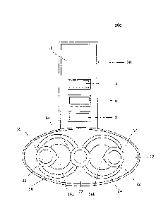
FIG. 1 is a top plan view of the hair braiding device 100 according to one
exemplary embodiment of
the present invention. The hair braider contains a handle 10 and an elliptical
head portion both
contained within a plastic outer shell 20.
The handle 10 includes a primary portion that is disposed to the head at a
1800 angle and a secondary
portion which is angled 90 to the primary portion whilst being perpendicular
in orientation to the
head.
The primary handle portion, which is attached to the head, includes a
plurality of buttons which control
the operations of several elements of the device 100. The buttons included in
the primary handle
portion are constructed such that there is a stop button 4, a start button 6
and a button activating the
operations of the secondary sliding clamp 8.
Constructed closest to the head portion is the secondary sliding clamp button
8 which operates the
motor 2 such that the sliding electromagnetic clamps 44 receive an electric
stimulus causing the
electromagnets 44 to attract and migrate toward one another, clamping the
section of hair tightly, and
furthermore slide down the cylinder such that a section of hair can be pulled
down within the device.
Farthest from the head portion is the stop button 4 which stops the operation
of the device 100 when
pressed wherein the motor 2 is deactivated. Located between the stop button 4
and the sliding clamp
button 8 is the start button 6 which operates the activation of
electromagnetic securing clamps 34
housed within each of the hair holding cylinders 22.
The secondary portion provides a handle section that can be grasped by the
user when operating the
device 100 and provides ergonomically easy access to the buttons which control
the operations of the
motor 2.
An external plastic elliptic cylinder shell casing 20 which also houses an
internal gear box 12 and sits
atop a plastic cylindrical shell casing 27 which surrounds a multiplicity of
cylindrical hair holding
chambers 26.
The tops of the chambers 26 are attached to rotatable gears 14 such that the
gears 14 are also attached
to rotatable gears 16a & 16b which sit on gears 14. The rotation of the
aforementioned gears can be
designed such that a figure-of-eight interchanging rotational motion is
achieved, such as described in
the previously mentioned Noh patent and Sapkus patent.
4
CA 02953631 2017-01-05
FIG. 2 is a side view of the head 20 and handle 10 portions and their
attachments, as well as a cross-
sectional view the casing for the hair holding chambers 27 for an embodiment
of the present patent.
The casing for the gear box 12 and the casing for the holding chambers 27 are
both connected by an
external plastic cylindrical shell 28. A plastic elliptic cylindrical shell
casing 30 which surrounds the
gears (14, 16a, 16b, 18, 22 & 24) and part of the hair holding chambers 22
sits atop the casing for the
gear box 20.
A cross-sectional view of the casing surrounding the hair holding chambers 27
is presented such that
the plastic casing for the three cylindrical hair holding chambers 26 is
visible. The sections of hair 50
inserted by the user into the hair holding chamber 22 is contained within the
cylinders 22 for the
duration of the operation of the device 100. When the stop button 4 is
activated, the activity of the
motor 2 is halted whereby the electromagnetic clamps 34 & 44 no longer attract
and the user may
remove the section of hair 50 from the hair holding chamber 22 in a safe
manner.
A side view of the tops of the hair holding chambers 22 are presented. Hair
sections are inserted by
the tips of the hair strands into the tops of the holding chambers 22 such
that a hair section is feed
through the continuous chamber tube 22 of which the majority of the tube is
housed within the shell
27 whereby a portion passes through the connector shell 28.
The secondary handle portion of the handle 10, which is angled 900 to the
primary handle portion,
consists of an internal motor 2, an internal sound box 11 and an external
outlet for the attachment of
a power source 24. The intended power source for the device 100 is a form of
conventional direct
current electric cable power source that may be plugged into wall sockets.
The internal motor 2 sits the handle 10 such that it may receive the electric
energy source from the
plugged cable attached at point 24.
The motor controls the rotation of the gears (14, 16a, 16b, 18, 22 & 24) as
directed by the operation
buttons 4, 6 & 8 of the handle and the emission of a high pitch low decibel
noise from the sound box
11. This noise alerts the user to the correct operation of the device upon
pressing the buttons 4, 6 &
8.
CA 02953631 2017-01-05
FIG. 3 illustrates a proposed configuration of the electromagnetic clamps and
springs within the hair
holding chambers of the present invention. While FIG. 4 are multiple operation
diagrams illustrating
configurations of the electromagnets of FIG. 3.
The Hair cylinder 22 contains an exterior casting 46 and 26 with a slit 38 in
the middle, where the
sections of hair can be inserted. There are two pairs of electrical clamps
34&46, where the closing
positions of the clamps will fill in the cavities within the slits of the
cylinder, and the opening of the
clamps will expose the opening of the slits 38. A pair of stationary
semicircle shaped electromagnetic
clamps 34 is present on top, attached to the sides of the cylinder 22 through
a pair of springs 32.
Underneath lies a pair of movable clamps 44, which are connected to a pair of
springs 42, connected
to the wall with a pair of sliders 40 indented into the walls of the cylinder
tube 46, where the sliders
can move up and down along the wall of the cylinder tube 46.
The closing of the stationary electric clamp 34 is activated by pressing the
button 6, while the
simultaneous closing and downward migration of the sliding clamps 44 are
controlled by the pressing
of button 8, and the opening of both clamps 34,44 as well as the upward
migration of the sliding
clamps 44 to their initial position are all activated by the pressing of
button 4.
FIG. 5 is a cross-sectional illustration of the hair holding chambers 38 with
hair secured within two
electromagnets 34 made from a ferromagnetic metal, such as, but not limited
to, iron wrapped by a
copper wire. The surface of each electromagnet in contact with the strand 50
is insulated and
cushioned with a material such as, but not limited to, felt. This will also
provide comfort to the user.
It is important to note that both pairs of electromagnets 34 and 44 (not
shown) function in the same
way, but for explanation purposes only the mechanism of the first
electromagnet will be explained. It
is also important to note that this mechanism is present in each of the three
rotating units 22.
This mechanism requires the springs 32 used in the retractable function of the
electromagnets 34.
Furthermore, these springs 32 will be attached to a holding apparatus 48 which
will enable the passing
of an electrical current provided by the power source 2 (not shown) to the
copper wire wrapping the
electromagnets 34. This current will create an electromagnetic field in each
electromagnet 34 of
opposite poles. This will cause their attachment therefore firmly trapping the
strand of hair 50 located
in the opening between the two electromagnets 38. Without current, the
electromagnets 34 are in their
relaxed state, therefore separated from each other by the springs 32 to leave
the channel 38 open and
the strand 50 will be loose. The current causes the polarized electromagnets
34 to overcome the
springs' 32 resistance and come together to clamp the strands 50 and
immobilize it.
6
CA 02953631 2017-01-05
These electromagnets 34 and their associated parts 32 and 48 are all confined
inside each of the three
rotating units 22. Each of these units are further segregated to an area 38
only accessible to the strands
of hair 50. This area 38 and the rotating unit 22 is composed of a plastic
polymer 36 and 46 allowing
the fluid rotation of each unit 22 during the braiding process and allowing
the strand to avoid
entanglement in the electromagnet's springs 32.
FIG. 6a and FIG. 6b are operation diagrams illustrating the motion of the
movable rotors per an
embodiment of the present invention. FIG. 6a is an overview of the gear system
that allows the
movement in a specific pattern of the rotors A 22 (not shown), B 22 and C 22
all equal size. It is
important to note that the movable rotors are based on US patent 4,369,690.
Originating from the motor 2 (not shown), it will power the movement of the
main gear 62. This gear
will cause the movement of a smaller gear 58 that is located overhead and
perpendicular to the
previous gear 62. This smaller gear 58 will be attached to a holder 60 to
allow it to be fixed in location.
This gear 58 will then enable the movement of the attachment units 54 and 56
with the presence of
the teeth found at their exterior 14.
The movement of the attachment units 54 and 56 is dictated by their elliptical
shape. The movement
of the main gear 62 turning in a clockwise manner will cause the attachment
unit teeth 14 to also move
in a clockwise manner.
FIG. 6b provides a close up of the attachment units 54 and 56 with their teeth
14 that provides it the
means to perform the braiding motion. The turning of the teeth 14 will cause a
180 rotation of units'
A 54 and B 56 in a clockwise manner which will cause a substitution in their
position. A
counterclockwise rotation will happen afterwards with the unit C 54 and unit A
54 (in the original
position of unit B 56). These two movements will be equal to one complete
maneuver of the device,
thus completing one braid of the three strands 50 (not shown) each inserted
into one of the rotors 22.
This movement will continue (with C exchanging with B and A with C, etc.) for
a fixed number of
maneuver with an auditory signal indicating the user to continue to the next
step.
Example of Use
A moderate portion of human hair is divided into three sections. One section
is inserted into a hair
holding chamber 22, in a tip to root direction, such that the hair section 50
falls through the holding
7
CA 02953631 2017-01-05
chamber 38 between the electromagnetic securing clamps 34 and the
electromagnetic sliding clamps
44. With the sections of hair 50 inserted within each of the hair holding
chamber 26, the button
controlling the secondary sliding clamp 8 is pressed and activated such that
within each hair holding
chamber 22 the sliding clamps 44 attract and the hair 50 is secured within the
partially contracted
clamps 44.
A low pitch beeping noise is emitted from the speaker box 11 signaling to the
user that the sliding
clamps have been activated. The action of the sliding clamps 44 allows the
entirety of the hair to be
passed through the hair holding chamber 22. The device 100 is then slide up
the hair length 50 close
to the roots of the hair 50. The start button of the device 6 is then pressed
causing the primary securing
clamp 34 to activate and contract upon the hair 50, the sliding clamps 44
simultaneously release and
expand around the hair 50, and a low pitch beeping noise is emitted from the
speaker box of the device
11. The gears (FIG. 6) then rotate the cylinders 26 in a figure-of-eight
pattern such that a single three-
bundle braid or plait is produced. When the hair between the scalp of the user
and the tops of the
cylinders 22 is too short to produce a braid, the user again may press the
button controlling the
secondary sliding clamp 8, whereby the gear rotation is halted and the primary
securing clamps 34 are
released. The secondary sliding clamps 44 activate and contract upon the hair
50 such that the hair 50
can be slid down the device 100, whereby more hair is available between the
scalp of the user and the
tops of the cylinders 22. Upon pressing the start button 6 once again, the
securing clamps 34 contract,
the speaker box 11 emits a low pitch beep, and the cylinders 22 are rotated by
the gears such that
braids are produced.
The alternation between the starting mode and the sliding mode produces braids
from the roots and
down the length of the portion of hair 50. When the satisfactory amount of
braids has been produced,
the user may press the stop button 4 such that the rotation of the cylinders
26 by the gears is brought
to a stop and the clamps 34 & 44 are released, therefore the hair sections 50
can be removed from the
cylinders 22 and the process may be repeated on another portion of hair.
8
CA 02953631 2017-01-05
References
1. Summers, Pamela, Angela Kyei, Wilma Fowler Bergfeld, and Melissa Piliang.
"Medical and
Environmental Risk Factors for the Development of Central Centrifugal
Cicatricial Alopecia:
A Population Study." Archives of Dermatology 147.8 (2011): 909-14.
9