Note: Descriptions are shown in the official language in which they were submitted.
CA 02954240 2017-01-04
WO 2016/004515
PCT/CA2015/050175
CONTROL SYSTEM FOR AN IMPROVED RAIL TRANSPORT SYSTEM FOR
CONVEYING BULK MATERIALS
CROSS REFERENCE TO RELATED APPLICATIONS
This application claims priority to U.S. provisional application No.
62/021,905, which is
herein incorporated by reference in its entirety.
FIELD OF THE INVENTION
The present invention generally relates to determining train position, and
more
particularly, to determining train position in automated train systems with no
internal
drive for conveying bulk materials.
BACKGROUND
Methods and arrangements for moving bulk materials in conventional trains,
trucks,
conveyor belts, aerial tramways or as a slurry in a pipeline are well known
and are
typically used in various industries because of site-specific needs or
experience. In the
minerals and aggregate industries, for example, bulk materials are moved from
mining
or extraction sites to a process facility for upgrading or sizing. Trucks had
been the
system of choice for many years for moving bulk materials. Trucks were
enlarged for
off-road vehicles because of their efficient transport of bulk materials and
increased
capacity. These vehicles, however, are limited to site specific applications
and are
provided at a high capital cost. Major off-road trucks have evolved that
require very wide
roadways for passing each other, are not energy efficient per ton-mile of
material
transported, have limited hill climbing ability, and are dangerous because of
potential of
operator error as well as being environmentally unpleasant neighbors.
Trains have been used for many years for bulk material transport in hopper
cars.
Because of low friction, due to free rolling iron or steel wheels on steel
tracks trains are
very efficient users of energy but are limited in capacity relative to the
drivers or
locomotives required. Large tonnage long trains use multiple drivers that are
heavy
units, which dictate the weight of rail and ballast requirements. All
railroads must be
1
CA 02954240 2017-01-04
WO 2016/004515
PCT/CA2015/050175
designed for the weight of the drivers or locomotives including fuel, not the
combination
of car plus loads, which are significantly less. The drivers need to be of
sufficient weight
so that the rotary drive tire makes contact with the stationary rail and must
have
sufficient friction to produce forward or reverse movement of what will
include heavily
loaded cars. The level of inclination that conventional railroad systems are
capable of
traversing is limited to the friction between the weighted drive wheels and
track. Rail
cars are individual units that each has to be loaded in a batch process, one
car at a
time. Bulk materials can be unloaded from hopper cars by opening bottom dump
hatches or can be individually rotated to dump out of the top. Spotting cars
for both
loading and unloading is time consuming and labor intensive.
Although moving from one location to another may be cost effective, the added
cost of
batch loading and unloading stages in shorter distance transports reduces the
rail
transport cost effectiveness. With normal single dual track train systems only
one train
can be used on a system at a time.
Conveyor belts have been used for many years to move bulk materials. A wide
variety
of conveyor belt systems exist that can move practically every conceivable
bulk
material. Very long distance single belt runs are very capital cost intensive
and are
subject to catastrophic failure when a belt tears or rips, typically shutting
down the entire
system and dumping the carried load, requiring cleanup. Conveyor belts are
relatively
energy efficient but can require high maintenance because of an inherent
problem of
multiple idler bearings requiring constant checking and replacement. Short
distance
conveyor belts are commonly used in dry or clamp transport of almost all types
of
materials. Because conveyor belts are very flexible and desirably operated
over fairly
flat terrain, they are not efficient at transporting moderately high solids
slurry where
water and fine particles can accumulate in low spots and spill over the side
creating wet
spilled slurry handling problems.
Some bulk materials can be transported in pipelines when mixed with water to
form a
slurry that is pushed or pulled with a motor driven pump impeller in an
airless or flooded
environment. The size of the individual particles that are present in the bulk
materials
2
CA 02954240 2017-01-04
WO 2016/004515
PCT/CA2015/050175
dictates the transport speed necessary to maintain movement. For example, if
large
particles are present then the velocity must be high enough to maintain
movement by
saltation or skidding along the bottom of the pipe of the very largest
particles. Because
pipelines operate in a dynamic environment, friction is created with the
stationary pipe
wall by a moving fluid and solid mass. The higher the speed of the moving mass
the
higher the friction loss at the wall surface requiring increased energy to
compensate.
Depending on the application, the bulk material has to be diluted with water
initially to
facilitate transport and dewatering at the discharge end.
Light rail, narrow gage railroads for transporting bulk material from mines
and the like is
known as described by way of example with reference to U.S. Pat. No. 3,332,535
to
Hubert et al. wherein a light rail train made up of several cars is propelled
by drive
wheels and electric motors combinations, dumping over an outside loop. By way
of
further example, U.S. Pat. No. 3,752,334 to Robinson, Jr. et al. discloses a
similar
narrow gage railroad wherein the cars are driven by an electric motor and
drive wheels.
U.S. Pat. No. 3,039,402 to Richardson describes a method of moving railroad
cars
using a stationary friction drive tire.
While the above described transport systems and methods have specific
advantages
over conventional systems, each is highly dependent upon a specific
application. It has
become apparent that increases in labor, energy and material costs as well as
environmental concerns, that alternate transport methods need to be applied
that are
energy and labor efficient, quiet, non-polluting, and esthetically
unobtrusive. US Patent
Publications US 2003/0226470 to Dibble et al. for "Rail Transport System for
Bulk
Materials", US 2006/0162608 to Dibble for "Light Rail Transport System for
Bulk
Materials", and U.S. Pat. No. 8,140,202 to Dibble describe a light rail train
utilizing an
open semi-circular trough train with drive stations, the disclosures of which
are herein
incorporated by reference in their entirety. Such a light rail system offers
an innovative
alternative to the above mentioned material transport systems and provides for
the
transport of bulk materials using a plurality of connected cars open at each
end except
for the first and last cars, which have end plates. The train forms a long
open trough and
has a flexible flap attached to each car and overlapping the car in front to
prevent
3
CA 02954240 2017-01-04
WO 2016/004515
PCT/CA2015/050175
spillage during movement. The lead car has four wheels and tapered side drive
plates in
the front of the car to facilitate entry into the drive stations. The cars
that follow have two
wheels with a clevis hitch connecting the front to the rear of the car
immediately
forward. Movement of the train is provided by a series of appropriately placed
drive
stations having drive motors on either side of the track which are AC electric
motors
with drive means such as tires to provide frictional contact with the side
drive plates. At
each drive station, each drive motor is connected to an AC inverter and
controller for
drive control, with both voltage and frequency being modified as needed. The
electric
motors each turn a tire in a horizontal plane that physically contacts two
parallel side
drive plates external of the wheels of each car. Pressure on the side drive
plates by
these drive tires converts the rotary motion of the tires into horizontal
thrust. The wheels
on the cars are spaced to allow operation in an inverted position by use of a
double set
of rails to allow the cars to hang upside down for unloading. By rotating this
double track
system the unit train can be returned to it normal operating condition. Such a
system is
well known and commercially referred to as the Rail-VeyorTM material handling
system.
Flanged wheels may be symmetrical to the side drive plates allowing operation
in an
inverted position which, when four rails are used to encapsulate the wheel
outside loop
discharge of the bulk material is possible. By using elevated rails, the train
can operate
in the inverted position as easily as in the conventional manner.
Yet further, drives for such light rail systems have been developed as
described in U.S.
Pat. No. 5,067,413 to Kiuchi et al. describing a device for conveying
travelable bodies
which are provided no driving source, on a fixed path. A plurality of
travelable bodies
travels on the fixed path while aligned substantially in close contact with
each other.
Traveling power is transmitted to one of a plurality of travelable bodies
which is
positioned on at least one end of the alignment. The traveling power drives
the
travelable body with frictional force while pressing one side surface of the
travelable
body, and is transmitted to the travelable body while backing up the other
side surface
of the travelable body. A device to transmit traveling power is arranged on
only a part of
the fixed path.
4
CA 02954240 2017-01-04
WO 2016/004515
PCT/CA2015/050175
it is known to sense a train's position by using an arrangement of proximity
sensors
located so as to sense both a train's side plate and each wheel of the train
as it
approaches and passes a drive station, as disclosed in U.S. Patent No.
8,140,202 for
"Method of Controlling a Rail Transport System for Conveying Bulk Materials"
the
disclosure of which is herein incorporated by reference in its entirety.
Although the train position determination systems and methods employed therein
have
been found effective, a need exists for a further optimized or improved
system.
SUMMARY OF THE INVENTION
In at least some embodiments, the present invention provides for systems and
methods
for sensing a train position of a train with no internal drive operating in an
automated
train system. According to one embodiment of the present invention, a train
system
comprises a track extending in a travel direction, a plurality of cars riding
on the track
and connected to form a train, a position sensing unit, and a programmable
logic
controller (PLC) in signal communication with the position sensing unit and
configured
to determine a train position based on inputs therefrom.
In one embodiment of a position sensing unit, each of the plurality of cars
has a
substantially identical car length in the travel direction and there are a
plurality of car
detection elements on the plurality of cars. Each of the plurality of car
detection
elements has a substantially identical detection element length in the travel
direction,
the detection element length being less than the car length.
The position sensing unit may include a first position sensor arranged along
the track
responsive to the presence and/or absence of each of the plurality of car
detection
elements and a second position sensor arranged along the track responsive to
the
presence and/or absence of each of the plurality of car detection elements and
separated from the first position sensor in the travel direction by a first
sensor spacing,
the first sensor spacing being less than the detection element length.
According to one embodiment of alternate position sensing unit, the cars are
connected
in a car order and a plurality of data tags are arranged on the plurality of
cars, each of
5
CA 02954240 2017-01-04
WO 2016/004515
PCT/CA2015/050175
the plurality of data tags storing a unique identifier. The position sensing
unit includes a
data tag reader arranged along the track and operable to detect each of the
plurality of
data tags in sequence and read the unique identifiers therefrom. The
programmable
logic controller stores a list of the unique identifiers corresponding to the
car order and
is configured to determine a train position based on inputs from the position
sensing unit
and the stored list.
In one embodiment, the present invention provides for an rail transport system
for
conveying bulk materials, including:
a plurality of cars adapted to form a train, each car having a pair of side
drive
plates and is adapted for carrying the bulk materials,
a drive station for frictionally contacting the side drive plates of at least
some of
the cars for imparting a driven movement to each contacted car, and
a sensor arrangement associated to the drive station for sensing a car
detection
element associated to at least one of the cars,
wherein the sensor arrangement is adapted to determine attributes associated
with the car wherein the attribute is the speed of the car, speed of the train
associated
with the car, acceleration rate of the car, acceleration rate of the train
associated with
the car, direction of movement of the car, derailment of the car, or
derailment of the train
associated with the car.
In a further embodiment of the rail transport system or systems outlined
above, the
sensor arrangement is further adapted to determine attributes associated with
the car
selected from a group consisting of location of the car and location of the
train.
In a further embodiment of the rail transport system or systems outlined
above, the drive
station includes a drive tire arrangement for frictionally contacting the side
drive plates
of at least one of the cars, and wherein the drive tire arrangement is
controlled based on
the determined attributes of one of the cars.
6
CA 02954240 2017-01-04
WO 2016/004515
PCT/CA2015/050175
In a further embodiment of the rail transport system or systems outlined
above, the drive
unit is adapted to control the drive tire arrangement to increase driven
movement from
the drive tire arrangement to a car engaged thereto in response to the
determined
attribute.
In a further embodiment of the rail transport system or systems outlined
above, the drive
unit is adapted to control the drive tire arrangement to decrease driven
movement from
the drive tire arrangement to a car engaged thereto in response to the
determined
attribute.
In a further embodiment of the rail transport system or systems outlined
above, the
sensor arrangement is a proximity sensor, a magnetic proximity sensor, or an
ultra-
sonic sensor.
In a further embodiment of the rail transport system or systems outlined
above, the
sensor arrangement is a multiple sensor arrangement.
In a further embodiment of the rail transport system or systems outlined
above, the car
detection element has an effective area such that only one of the sensors
detects the
car detection element at one time.
In a further embodiment of the rail transport system or systems outlined
above, as each
car passes near the drive station, each sensor sequentially detects the car
detection
element of the car.
In a further embodiment of the rail transport system or systems outlined
above, the
sensor arrangement is a three sensor arrangement with a known pre-determined
spacing between each sensor.
7
CA 02954240 2017-01-04
WO 2016/004515
PCT/CA2015/050175
In a further embodiment of the rail transport system or systems outlined
above, as each
car passes near the drive station, each sensor sequentially detects the car
detection
element of the car.
In a further embodiment of the rail transport system or systems outlined
above, the car
detection element of the car sensed by the sensor arrangement is located
between the
front of the car and a subsequent car.
In another embodiment, the present invention provides for a control system for
a rail
transport system for conveying bulk materials, wherein the rail transport
system
includes a plurality of cars adapted to form at least two separate trains, and
wherein at
least one car of each train has a pair of side drive plates and is adapted for
carrying the
bulk materials, the rail transport system further including at least one drive
station for
frictionally contacting the side drive plates for imparting a driven movement
to each
train, the control system comprising:
a sensor arrangement for sensing a car detection element of at least one car
of
each of the trains,
wherein the sensor arrangement is adapted to determine status information
associated with the at least one car wherein the status information is the
speed of the
car, speed of the train associated with the car, acceleration rate of the car,
acceleration
rate of the train associated with the car, direction of movement of the car,
derailment of
the car, or derailment of the train associated with the car.
In a further embodiment of the control system or systems outlined above, the
sensor
arrangement is operatively coupled to the drive station.
In a further embodiment of the control system or systems outlined above, as a
car
passes near the drive station, the sensor arrangement detects the
corresponding car
detection element of the car.
8
CA 02954240 2017-01-04
WO 2016/004515
PCT/CA2015/050175
In a further embodiment of the control system or systems outlined above, the
sensor
arrangement is located separate and apart from the drive station.
In a further embodiment of the control system or systems outlined above, the
sensor
arrangement is further adapted to determine attributes associated with the car
of
location of the car or location of the train.
In a further embodiment of the control system or systems outlined above, the
drive
station includes a drive unit and a drive tire arrangement for frictionally
contacting the
side drive plates of at least some of the cars, and wherein the drive unit is
adapted to
control the drive tire arrangement in response to the determined attributes of
one of the
cars.
In a further embodiment of the control system or systems outlined above, the
drive unit
is adapted to control the drive tire arrangement to increase driven movement
from the
drive tire arrangement to a car engaged thereto in response to the determined
attribute.
In a further embodiment of the control system or systems outlined above, the
drive unit
is adapted to control the drive tire arrangement to decrease driven movement
from the
drive tire arrangement to a car engaged thereto in response to the determined
attribute.
In a further embodiment of the control system or systems outlined above, the
sensor
arrangement is a multiple sensor arrangement.
In a further embodiment of the control system or systems outlined above, the
sensors
are a proximity sensor, a magnetic proximity sensor, or an ultra-sonic sensor.
In yet another embodiment, the present invention provides for a method for
controlling a
rail transport system for conveying bulk materials, wherein the rail transport
system
includes a train having a pair of side drive plates and is adapted for
carrying the bulk
materials, wherein the rail transport system further includes at least two
drive stations
9
CA 02954240 2017-01-04
WO 2016/004515
PCT/CA2015/050175
for frictionally contacting the side drive plates for imparting a driven
movement to the
train, the method comprising:
imparting a driven movement to the train at a select speed and acceleration at
the first drive station,
determining the position of the train relative to the second drive station,
and
when the train is determined to be at a select position relative to the second
drive
station, initiating the second drive station such that driven movement is
imparted to the
train at the second drive station to maintain substantially the same speed of
the train as
when the train was at the first drive station.
In a further embodiment of the method or methods outlined above, the method(s)
further
include the step of
stopping operation of the second drive station if the second drive station is
not at
a condition for imparting to the train driven movement to maintain
substantially the same
speed of the train as when the train was at the first drive station.
In a further embodiment of the method or methods outlined above, the at least
two drive
stations are positioned apart a greater distance than the length of the train.
In yet another embodiment, the present invention provides for a method for
controlling a
rail transport system for conveying bulk materials, wherein the rail transport
system
includes a train having a pair of side drive plates and is adapted for
carrying the bulk
materials, wherein the rail transport system further includes a drive station
for frictionally
contacting the side drive plates for imparting a driven movement to the train,
the method
comprising:
determining the position of the train relative to the drive station, and
when the train is determined to be at a select position relative to the drive
station,
initiating the drive station to impart driven movement to the train at a
desired speed
when the train passes therethrough.
10
CA 02954240 2017-01-04
WO 2016/004515
PCT/CA2015/050175
In a further embodiment of the method or methods outlined above, the rail
transport
system further includes a second drive station for frictionally contacting the
side drive
plates for imparting a driven movement to the train, and wherein the method
further
comprises:
ensuring that at least one of the cars of the train is in contact with one of
the drive
stations at all times.
In a further embodiment of the method or methods outlined above, the rail
transport
system further includes a second drive station for frictionally contacting the
side drive
plates for imparting a driven movement to the train, and wherein the distance
between
two drive stations is longer than a length of the train.
In a further embodiment of the system or systems outlined above, the system
further
comprises a plurality of cars adapted to form a second train, each car having
a pair of
side drive plates and is adapted for carrying the bulk materials.
In yet another embodiment, the present invention provides for a train system
comprising:
a track extending in a travel direction;
a plurality of cars situated on the track and connected to form a train;
a plurality of car detection elements on the plurality of cars, each of the
plurality
of car detection elements having a substantially identical detection element
length in the
travel direction, the detection element length being less than the car length;
a position sensing unit including:
a first position sensor arranged along the track responsive to the presence
and absence
of each of the plurality of car detection elements;
a second position sensor arranged along the track responsive to the presence
and
absence of each of the plurality of car detection elements and separated from
the first
position sensor in the travel direction by a first sensor spacing, the first
sensor spacing
being less than the detection element length; and
11
CA 02954240 2017-01-04
WO 2016/004515
PCT/CA2015/050175
a programmable logic controller (PLC) in signal communication with the
position
sensing unit and configured to determine a train position based on inputs
therefrom.
In a further embodiment of the system or systems outlined above, the position
sensing
unit further includes a third position sensor arranged along the track
responsive to the
presence and absence of each of the plurality of car detection elements,
separated by
the second position sensor in the travel distance by a second sensor spacing
and
separated from the first position sensor by a third sensor spacing equal to
the sum of
the first and second sensor spacings, the second sensor spacing being less
than the
detection element length.
In a further embodiment of the system or systems outlined above, the third
sensor
spacing is greater than the detection element length.
In a further embodiment of the system or systems outlined above, the first and
second
sensor spacings are unequal.
In a further embodiment of the system or systems outlined above, the third
sensor
spacing is less than the car length.
In a further embodiment of the system or systems outlined above, the track
includes a
pair of parallel rails and the position sensing unit is arranged between the
rails such that
the train passes thereover.
In a further embodiment of the system or systems outlined above, the position
sensing
unit includes a sensor mount elongated in the travel direction and the
position sensors
are mounted thereto.
In a further embodiment of the system or systems outlined above, each of the
plurality
of car detection elements is a metal member extending under a respective one
of the
plurality of cars; and
12
CA 02954240 2017-01-04
WO 2016/004515
PCT/CA2015/050175
wherein each of the position sensors is a proximity detector responsive to the
presence and absence of each metal member.
In a further embodiment of the system or systems outlined above, the system(s)
further
comprises a drive station arranged along the track and operable by the PLC to
impart
motion to the train.
In a further embodiment of the system or systems outlined above, the drive
station
includes a pair of drive wheels on opposite sides of the track, the drive
wheels engaging
each of the plurality of cars when passing therebetween.
In a further embodiment of the system or systems outlined above, the position
sensing
unit is located at the drive station.
In a further embodiment of the system or systems outlined above, the system(s)
further
comprises:
a plurality of additional drive stations arranged along the track at intervals
and
operable by the PLC to impart motion to the train; and
a plurality of additional position sensing units identical to the position
sensing
unit, each of the plurality of additional position sensing units being located
a respective
one of the plurality of additional drive stations.
In a further embodiment of the system or systems outlined above, the PLC is
configured
to sequentially operate the drive stations based on the input from the
position sensing
units.
In a further embodiment of the system or systems outlined above, each of the
plurality
of cars has a substantially identical car length in the travel direction.
In yet another embodiment, the present invention provides for a train system
comprising:
13
CA 02954240 2017-01-04
WO 2016/004515
PCT/CA2015/050175
a track extending in a travel direction;
a plurality of cars situated on the track and connected in a car order to form
a
train;
a plurality of data tags on the plurality of cars, each of the plurality of
data tags
storing a unique identifier;
a position sensing unit including:
a data tag reader arranged along the track and operable to detect each of the
plurality
of data tags in sequence and read the unique identifiers therefrom; and
a programmable logic controller in signal communication with the position
sensing unit, the programmable logic controller storing a list of the unique
identifiers
corresponding to the car order and being configured to determine a train
position based
on inputs from the position sensing unit and the stored list.
In a further embodiment of the system or systems outlined above, the plurality
of data
tags are radio frequency identification (RFID) tags and the data tag reader is
a RFID tag
reader.
In a further embodiment of the system or systems outlined above, the RFID tags
are
passive RFID tags.
In a further embodiment of the system or systems outlined above, the plurality
of data
tags are not located on outer surfaces of the plurality of cars.
In a further embodiment of the system or systems outlined above, the system(s)
further
comprises a drive station arranged along the track and operable by the PLC to
impart
motion to the train.
In a further embodiment of the system or systems outlined above, the PLC is
configured
to bring the train to a controlled stop if one of the unique identifiers is
not read at its
place in the car order.
14
CA 02954240 2017-01-04
WO 2016/004515
PCT/CA2015/050175
In a further embodiment of the system or systems outlined above, the position
sensing
unit is located at the drive station.
In a further embodiment of the system or systems outlined above, the system(s)
further
comprises:
a plurality of additional drive stations arranged along the track at intervals
and
operable by the PLC to impart motion to the train; and
a plurality of additional position sensing units identical to the position
sensing
unit, each of the plurality of additional position sensing units being located
a respective
one of the plurality of additional drive stations.
In a further embodiment of the system or systems outlined above, the PLC is
configured
to sequentially operate the drive stations based on the input from the
position sensing
units.
In a further embodiment of the system or systems outlined above, the intervals
are
greater than the length of the train PLC calculates the expected speed of the
train when
reaching a subsequent drive station based on the location of the train, the
topography
and track conditions and starts the subsequent drive station to cause the
subsequent
drive station to impart force to the train such that it maintains
substantially the same
speed as when it first reached the subsequent drive station.
BRIEF DESCRIPTION OF THE DRAWINGS
Various embodiments of the invention are described by way of example with
reference
to the accompanying drawings and appendices. The present invention will be
apparent
to those skilled in the art by reading the following detailed description of
various
embodiments thereof, with reference to the attached drawings, in which:
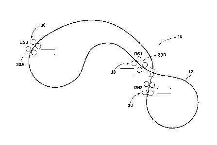
Figure 1 is a diagrammatical illustration of one rail system in keeping with
the teachings
of the present invention;
CA 02954240 2017-01-04
WO 2016/004515
PCT/CA2015/050175
Figures 2 and 3 are side and top plan views, respectively, of one embodiment
of a train
operable with the system of Figure 1;
Figure 4 is a diagrammatical illustration of a track arrangement operable with
a control
system of the present invention;
Figure 5 is a schematic overview of a train system with position sensing
units, according
to a further embodiment of the present invention;
Figure 6 is a side view of a portion of the train system of Figure 5, with a
train thereon
shown in partial cutaway to reveal hidden components;
Figure 7 is a top view of a portion of the train system of Figure 5, including
a drive
station with the train of Figure 6 passing therethrough, with hidden
components shown
in broken lines;
Figure 8 is a top view of the drive station of Figure 7, with components
removed and the
train absent, showing an exemplary position sensing unit of Figure 5;
Figure 9 is a series of schematic side views of a train passing over one of
the sensing
units of Figure 5;
Figure 10 is a state diagram of states of the position sensing unit of Figure
9 as the train
passes thereover; and
Figure 11 is a top view of a portion of the train system of Figure 5,
including a drive
station with the train of Figure 6 passing therethrough past an alternate
position sensing
unit embodiment, with hidden components shown in broken lines.
DETAILED DESCRIPTION
The present invention will now be described more fully hereinafter with
reference to the
accompanying drawings and appendices, in which illustrative embodiments of the
invention are shown. This invention may, however, be embodied in many
different forms
and should not be construed as limited to the embodiments and examples set
forth
16
CA 02954240 2017-01-04
WO 2016/004515
PCT/CA2015/050175
herein nor should the invention be limited to the dimensions set forth herein.
Rather, the
embodiments herein presented are provided so that this disclosure will be
thorough and
complete, and will fully convey the scope of the invention to those skilled in
the art by
way of these illustrative and non-limiting embodiments and examples. It will
be
understood to the person of skill in the art that many different forms and
variations of the
embodiments, examples and illustrations provided herein may be possible, and
the
various embodiments, examples, and illustrations provided herein should be
construed
as non-limiting embodiments, examples, and illustrations.
With reference initially to Figures 1-3, one train system 10, in keeping with
the teachings
of the present invention, comprises a track 12 having parallel rails 12a, 12b.
A train 14
includes a first or lead car 16 having both forward and rear wheel pairs 18,
20 operable
on the track 12 for providing a free wheeling movement to the lead car. For
the
embodiment herein described by way of example, the train includes additional
cars
described as a second or rear car 22 and an intermediate car 24 or multiple
intermediate cars carried between the lead and rear cars. The rear and
intermediate
cars 22, 24 include a forward pivotal connection 26 for pivotally connecting
the
intermediate and rear cars to adjacent forward cars. The rear and intermediate
cars 22,
24 have only rear wheel pairs 20 operable on the track 12 for providing a free
wheeling
movement thereto.
With continued reference to Figure 2, each of the cars has a side plate 28
affixed
thereto. With reference to Figures 1, 3-4, multiple drive stations 30 each
have a variable
frequency drive (VFD) including a drive tire 32 for frictionally contacting
the side plate 28
and imparting a driven movement to each car and thus the train 14. As
illustrated with
continued reference to Figure 3, the embodiment herein described includes each
car
having opposing side plates 28a, 28b and opposing drive tires 32a, 32b.
Specifically,
each car may have a fixed side plate on each side, which runs the length of
the car and
spaced outside the wheels and tracks. These side plates may be located
symmetrically
with the wheels and parallel to the light rails. In another arrangement, the
side plates
may be located asymmetrical with the wheels. However, in this arrangement, the
wheels are part of the side plates such that the sideplate-wheel arrangement
allows the
17
CA 02954240 2017-01-04
WO 2016/004515
PCT/CA2015/050175
train to be moved either downstream or upstream. Preferably, the wheels are
placed to
allow the train to operate in either an upright or an inverted position. Each
drive stations
30 includes A/C inverters and a controller connected to every set of drive
motors such
that the motors may be synchronized through a modifying of at least one of
voltage and
frequency thereto. Forward or reverse motion of the train is the result of
horizontal
rotation of tires on opposite sides of the train turning in opposite
directions with suitable
pressure of said rotation that provides minimal slip between the tire surface
and side
plates. In other words, the two opposing tires are both pushed inward toward
the center
of the track. In order the stop the train, the drive tires 32 are further
adapted to engage
and apply pressure to the side plate 28 of the car.
As herein illustrated, the lead car 16 has a trough 54, and opposing side
plates 28a, 28b
having a reduced distance between them for smooth entrance into opposing drive
tires
32a, 32b of the drive station. The rear car 22 has a trough and opposing side
plates
28a, 28b at a reduced distance between them to reduce shock when the train 14
exits
the opposing drive tires 32a, 32b of the drive station 30. The intermediate
cars 24
coupled to the lead car 16 and the rear car 22 by the clevis type coupling has
its trough
aligned to produce an overall open trough with gaps 56 between cars. A
flexible flap 58
extends over the gap 56 between the cars 16, 24, 22. The cars, each consist of
a semi-
circle open trough and when joined or coupled together represents an open and
continuous rigid trough for the entire length of the train. A flexible sealing
flap attached
near the front of the trailing car overlaps but is not attached to the rear of
the lead car
trough. A semi-circular trough is much better sealed with the flexible flap
that other
designs such as showed in U.S. Pat. No. 3,752,334. This allows the train to
follow the
terrain and curves without losing its sealed integrity as a continuous trough.
The
material to be transported in the train is effectively supported and sealed by
this flap as
the material weight is equally distributed maintaining the seal against the
metal trough
of the forward car. The long continuous trough provides for simplified loading
as the
train can be loaded and unloaded while moving similar to a conveyor belt. This
is a
significant advantage over the batch loading equipment requirements of a
conventional
railroad hopper or rotary dump car.
18
CA 02954240 2017-01-04
WO 2016/004515
PCT/CA2015/050175
As set forth herein and with reference to Figure 4, a system and method of
controlling
the rail transport system is provided, which is focused on the train (rather
than the drive
stations) and is optimized to determine the location of the train along the
track to at least
within one car length. Referring back to Figures 1-4, drive stations 30 are
spaced along
the track 12 such that at least one drive station has contact with a train in
order to
maintain adequate control. A control center 48 may be remotely located from
the drive
stations 30 with each of the drive stations communicating with the control
center for
providing status information, such as train location, train speed, performance
of the
drive station itself, and the like. Communications from drive station to drive
station and
to the control center may employ hard wire, optical fiber, and/or radio wave
transmissions as is desired for the conditions within which the system is to
be operated.
This system allows the use of multiple trains. For example, a plurality of
trains may be
operated within a system comprising multiple drive stations 30 in
communication with
each other for driving both trains and maintaining a desirable spacing between
the
trains. As will come to the mind of those skilled in the art, now having the
benefit of the
teachings of the present invention, alternate track and drive station
configurations are
anticipated including a reinversion location for reversing the direction of
the train or
trains traveling within the system.
With regard to operation of the drive control system, only the drive in
contact with the
train will preferably be running at any given point in time. The control
system uses the
trains' location information to make small adjustments in train speed to
assure the
proper spacing of all trains on the course. With regard to acceleration rate,
incline grade
and incline length will likely determine the peak horsepower required by the
drive
motors. Because the control system is capable of communicating drive speed
information between drive stations for synchronization purposes, a train need
not be
fully accelerated before entering the next drive station. In addition, longer
acceleration
times allow the use of smaller horsepower (lower cost) drive motors.
With continued reference to Figure 4, a method of controlling the rail
transport system
comprising a train 14 and drive stations 30 is provided and may be optimized
to
determine the location of the train 14 along the track 12, optionally, to at
least within one
19
CA 02954240 2017-01-04
WO 2016/004515
PCT/CA2015/050175
car length. Specifically, each of the drive stations 30 includes sensors, for
example at
least three sensors, spaced generally apart from one another so as to not
interfere with
each other. At least one of the cars, but ideally each of the cars, of the
train 14 includes
a corresponding car detection element (to be sensed by each of the sensors),
such that
when the train 14 passes through the drive station, each of the sensors may
sense the
corresponding car detection element of each car. The corresponding car
detection
element of the car may further be designed such that only one of the three
sensors at
the drive station 30 detects such car detection element at one time.
In one example, each of the drive stations 30 includes three sensors spaced
generally
horizontally apart from one another at a select sufficient length so as to not
interfere
with each other (e.g., Sensor A, Sensor B, and Sensor C generally spaced at
least
about 18 inches apart). Each of the cars of the train 14 includes a
corresponding car
detection element (to be sensed by each of the sensors) having an effective
area such
that only one of the three sensors at the drive station 30 detects such car
detection
element at one time. The sensors may be a proximity, ultra-sonic, magnetic
proximity
or other comparable or suitable sensor. In this example, the proximity or
ultra-sonic
type sensors would each be used to detect a select surface area on each car,
whereas
the magnetic proximity sensor would be used to detect a magnet (e.g., a
neodymium
magnet) mounted on each car. The car detection element can be an integral part
of the
car, or mounted onto the car.
Using the three sensors, the control system is adapted to determine the
location of the
train 14 along the track 12 to at least within one car length. Specifically,
as each car of
the train 14 passes through a drive station 30, each sensor sequentially
detects the
corresponding car detection element of a car and transmits an associated
signal to the
control system. In this way, presence or location of any one car of the train
may be
ascertained through this sensor arrangement at each of the drive stations.
This sensor arrangement may also be used to determine direction of movement by
the
train. For example, when a train is moving through a drive station in a
forward direction,
a corresponding car detection element on each car triggers sensor A, then
sensor B
CA 02954240 2017-01-04
WO 2016/004515
PCT/CA2015/050175
and then sensor C, to send associated signals in sequence to a control center.
When
the control center receives the associated signals in this sequence (e.g.,
sensed A,
sensed B, sensed C), the control center assumes that one car has passed
through the
drive station upstream (or in a forward motion). When a train is moving
through a drive
station in a reverse direction, a corresponding car detection element on each
car
triggers sensor C, then sensor B and then sensor A, to send associated signals
in
sequence to the control center. When the control center receives the
associated
signals in this reverse sequence (e.g., sensed C, sensed B, sensed A), the
control
center assumes that one car has passed through the drive station downstream
(or in
reverse). If the control center receives any other sequence than (sensed A,
sensed B,
sensed C) or (sensed C, sensed B, sensed A), stoppage of the train or a fault
may be
assumed.
The sensor arrangement may also be used to determine speed and acceleration of
the
train. For example, using (a) the distance between the corresponding car
detection
elements of two cars and (b) the length of time between the detection of
sensors (e.g.,
(a) the distance between a magnet located on car 1 and a magnet located on car
2, and
(b) the length of time between the detection of the magnet located on car 1
and the
magnet of car 2 by sensor A), the speed of the train may be determined.
Furthermore,
sensor data over time or the sensing of multiple cars over time may be used to
determine acceleration of the train.
As discussed above, the sensor arrangement may generally be used to detect a
stoppage of the train or a fault. Derailments can be caused by a number of
factors, for
example from debris on the track to the failure of a wheel bearing on the
train. In one
specific example, the sensor arrangement may be used to detect derailment of
the train.
The detection of a folded train is generally performed by comparing the number
of cars
between drive stations. Specifically, the sensor arrangement may be used to
sense the
number of corresponding car detection elements on each car and, therefore,
count cars
that pass through a drive station. For example, if (a) drive stations D1 and
D2 are 1140
ft apart and (b) each car is 67 ft in length each, there should be 17 cars
between each
drive station. If the difference of car count between each drive station is
less than 17
21
CA 02954240 2017-01-04
WO 2016/004515
PCT/CA2015/050175
cars or greater than 18 cars, then the control center assumes a possible
derailment or a
sensor failure. In turn, a signal can be sent to the drive station to stop the
train.
In yet another embodiment, a control system is provided which can mitigate
damage
from derailment by ensuring that the speed of each drive tire at an
approaching drive
station (e.g., D2) is maintained at the same speed as the train. Specifically,
an
improved system and method is provided for controlling the movement of the
train 14
along the track 12 based on the speed or acceleration detected at a preceding
drive
station. In one example, a first drive station 30 (DS1) moves the train along
the track 12
at a preselected speed or acceleration toward a second drive station (DS2).
The cars of
the train are sensed by the sensor arrangement described above, and the
position of
the train 14 relative to the first drive station (DS1) and the second drive
station (D52)
are ascertained. When the train 14 is determined to be within a certain
distance from
the second drive station (D52), a command signal is transmitted to the second
drive
station (D52), which initiates the drive tire 32 at the second drive station
(D52). In order
to reduce wear of the drive tire and cars, the second drive station (D52)
engages and
maintains the train at about the same speed and/or acceleration as at the
first drive
station speed. In other words, the second drive station (D52) is initiated and
maintained
at the speed and/or acceleration rate assigned to the train by the control
center. When
select sensors at the second drive station (D52) provide a determination that
the
second drive station (D52) has engaged the train, a stop command is
transmitted to the
first drive station for the drive tire 32 of the first drive station to stop.
In this fashion, the
train will pass control from one drive station to another. The transition from
one drive
station to another is synchronized.
In various embodiments, the distance between neighbouring drive stations is
larger than
the length of the train. Therefore, the train runs free for a certain distance
between
drive stations. Therefore, the train is essentially passed off between drive
stations. In
this arrangement, the control system calculates the expected speed when the
train
reaches the second drive station based on the topography and track conditions
(incline
or decline of the track). The control system can then detect the location of
the train,
start the second drive station, and cause the second drive station to impart
force from
22
CA 02954240 2017-01-04
WO 2016/004515
PCT/CA2015/050175
the drive tires to the train such that it maintains substantially the same
speed as when it
first reached the second drive station.
In various other embodiments, the distance between the drive stations is
shorter than
the train and therefore the train is generally always in contact with a drive
station.
Many modifications and other embodiments of the inventions set forth herein
will come
to mind to one skilled in the art to which these inventions pertain having the
benefit of
the teachings presented in the foregoing descriptions and the associated
drawings.
Therefore, it is to be understood that the inventions are not to be limited to
the specific
examples of the embodiments disclosed and that modifications and other
embodiments
are intended to be included within the scope of the appended claims. Although
specific
terms are employed herein, they are used in a generic and descriptive sense
only and
not for purposes of limitation.
Referring to Figures 5 and 6, according to a further embodiment of the present
invention
a train system 110 includes a track 112 having one or more trains 114 riding
thereon.
The track 112 extends in a travel direction 116 and the trains 114 are driven
in (forward)
and counter to (reverse) the travel direction 116 by a plurality of drive
stations 120. A
plurality of position sensing units 122 each determines positions of the
trains 114. A
programmable logic controller (PLC) 124 is in signal communication with the
drive
stations 120 and position sensing units 122, and is configured to drive the
train 114 with
drive stations 120 based on the train positions determined by the position
sensing units
122.
Referring also to Figure 7, the track 112 may include a pair of generally
parallel rails
126, although other track 112 configurations may be employed. The track 112
can be
arranged in a continuous loop or have discrete start and end points.
Additionally, the
track can have distinct branches, elevated sections, inverted sections,
tunnels, etc. as
needed or desired. It will be appreciated that the present invention may be
employed
with virtually any track configuration.
23
CA 02954240 2017-01-04
WO 2016/004515
PCT/CA2015/050175
Referring to Figures 6 and 7, the train 114 includes a plurality of cars 130
connected
sequentially. A car length of each car in the travel direction 116 is
optionally
approximately equal. Additionally, the cars 130 may roll in both right-side up
and
inverted positions on wheels 134 allowing for dumping of the contents of the
car when in
an inverted position. The cars 130 depicted include side plates 136 that are
engaged
by the drive stations 120 in order to impel the cars 130 in and against the
travel
direction 116, as will be explained in greater detail below. Although only
three cars 130
are depicted for economy of illustration, trains composed of more or fewer
cars may
also be employed.
Each car 130 carries a car detection element 140 to the presence and absence
of which
the position sensing units 122 are responsive. As outlined above, the car
detection
element 140 can be an integral part of the car, or mounted onto the car. In
the depicted
embodiment, the car detection element 140 is a metal member elongated in the
travel
direction 116 and attached to the bottom of each car 130. In one embodiment,
the
length of the car detection element 140 in the travel direction is less than
the car length.
For example, the car detection element 140 can be an approximately 1 inch x 2
inch x 4
foot metal tube mounted to the bottom of an approximately 8 foot long car.
Referring to Figure 7, in the depicted embodiment, each drive station 120
includes a
pair of drive wheels 142 mounted on opposite sides of the track 112. More or
fewer
drive wheels/pairs could be employed based on operational requirements, or
another
driving mechanism may be employed. The drive wheels 142 are laterally
positioned in
direction 144 so as to engage the side plates 136 on the on the cars 130. With
the drive
wheels 142 powered to spin in direction 146, the train 114 is thereby impelled
forward in
the travel direction 116. The train 114 can be impelled in reverse against the
travel
direction by turning the drive wheels 142 opposite direction 146. The drive
wheels 142
can also be used to decelerate the train 114. The drive wheels 142 may be
powered by
one or more variable frequency (VFD) drives, as directed by the PLC 124.
Referring to Figure 8, an exemplary one of the position sensing units 122
includes a
plurality of position sensors 150, 152, 154 arranged one after the other in
the travel
24
CA 02954240 2017-01-04
WO 2016/004515
PCT/CA2015/050175
direction 116. The other units 122 may be substantially identical, but only
one is
illustrated for the sake of brevity. For ease of installation and replacement,
the sensors
150, 152, 154 are commonly located on a sensor mount 156. The sensor mount 156
is
arranged between the rails 126 of the track 112 such that the train 114 will
pass
thereover. In this arrangement, the sensors 150, 152, 154 are positioned such
that
each car detection element 140 passes within their nominal range; for example,
the car
detection elements 140 will pass approximately 0.750 inches over the position
sensors
150, 152, 154.
In the depicted embodiment, the sensors 150, 152, 154 are proximity sensors,
such as
inductive proximity sensors, that are responsive to the presence and absence
of the car
detection elements 140 without making physical contact therewith. The sensors
150,
152, 154 may be highly unresponsive to nonmetallic objects, and to any objects
outside
of their nominal range. With no moving parts and largely immune to
interference from
dust and dirt, such sensors can function reliably with little or no
maintenance in many
harsh environments.
In various embodiments, there are at least two position sensors, and the
depicted
embodiment includes first, second and third sensors 150, 152, 154. The first
and
second position sensors 150, 152 are separated in the travel direction 116, by
a first
sensor spacing 160. The third sensor 154 is separated from the second sensor
152 in
the travel direction 116 by a second sensor spacing 162. The first and third
sensors
150, 154 are separated in the travel direction 116 by a third sensor spacing
164, which
is equal to the sum of the first and second sensor spacings 160, 162. Although
different
numbers and spacings of sensors may be used, the following non-limiting
spacing
properties can be advantageous and form an illustrative embodiment of the
invention:
= the first and second sensor spacings 160, 162 are each less than the
detection
element length;
= the first and second sensor spacings 160, 162 are not equal to each
other;
= the third sensor spacing 164 is greater than the detection element
length; and
CA 02954240 2017-01-04
WO 2016/004515
PCT/CA2015/050175
= the third sensor spacing 164 is less than the car length; more
particularly less
than the spacing of detection elements from one car in the train to the next.
With the exemplary detection element length of approximately 4 feet and the
car length
of approximately 8 feet provided above, advantageous approximate measurements
for
the first, second and third sensor spacings are about 2 feet, 3 feet and 5
feet,
respectively.
The PLC 124 is in signal communication with the drive units 120 and the
position
sensing units 122. Generally speaking, the PLC determines train position from
the
position sensing units 122 and controls the drive units 120 (for example,
through one or
more VFDs) based thereon. As used herein "signal communication" refers to
communication effective to convey data. Various wired and/or wireless
communications
devices could be employed to effectuate signal communication between these
components.
The determination of "train position," as used herein, refers broadly to the
determination
of the physical location of the train and/or derivatives thereof, such as
train velocity and
train acceleration/deceleration. The present invention is primarily focused on
systems
and methods for determining train position ¨ the methods by which the PLC uses
the
determined train position to control trains can vary considerably within the
scope of the
present invention. However, the present invention, in one embodiment, may be
used in
support of a control routine like that in U.S. Patent No. 8,140,202,
referenced above and
herein incorporated by reference in its entirety, where the PLC synchronizes
drive wheel
speeds between drive stations as a train passes from one drive station to the
next.
A "PLC" should generally be understood to be a computer device equipped to
receive
sensor inputs and generate control outputs, and programmable with one or more
control
routines governing the operational relationship between the inputs and
outputs. While
the PLC may be a purpose-built PLC, such as are marketed for that purpose, the
present invention is not necessarily limited thereto.
26
CA 02954240 2017-01-04
WO 2016/004515
PCT/CA2015/050175
Referring to Figures 9 and 10, the operation of the position sensing unit 122
in
determining train 114 position will be explained in greater detail. Figures 9A-
9G
schematically illustrate positions of a leading (solid lines) and trailing
(broken lines) train
cars 130 with detection elements 140, as they pass over the first, second and
third
position sensors 150, 152, 154 (labeled A, B and C).
Each of the position sensors has a high/on output, indicative of the presence
of a
detection element 140 and a low/off output, indicative of the absence of a
detection
element 140 (although these states could be reversed while preserving the
overall
functionality described herein). Figure 10 illustrates sensor response over
time with the
cars of Figure 9 passing thereover (a constant car velocity is used for this
example).
Sensor activations for the leading car are shown in solid lines, while
switching to broken
lines for activations by the trailing car. Labeled vertical lines 9A-9G in
Figure 10
indicate sensor states at the car positions depicted in the corresponding
Figures 9A-9G.
In Figure 9A, the leading car is still approaching sensor A, thus all of the
sensors A, B
and C are low. When the leading car reaches the Figure 9B position, the
detection
element is over sensor A, but has not yet reached sensor B, so only sensor A
is high.
At the Figure 9C position, the detection element is over both sensors A and B,
so both
sensors are high. At Figure 9D, the detection element has cleared sensor A but
remains over sensor B, so sensor A goes low but B remains high ¨ until the
position of
Figure 9F, when sensor B also goes low.
Without discussing sensor C for the moment, it will be appreciated that use of
two
sensors (A and B), spaced apart by less than the length of a detection
element, offer a
very reliable indicator that a car has passed over the sensors ¨ without the
need for
extra debounce logic to rule out the possibility of intermittent false sensor
responses.
Before the PLC will count a car as having passed it will need to see the
following
events, in the following order (for the forward direction ¨ the order would be
reversed for
a car passing in the opposite or reverse direction):
= Sensor A transition to high while Sensor B is low;
27
CA 02954240 2017-01-04
WO 2016/004515
PCT/CA2015/050175
= Sensor B transition to high while Sensor A is high;
= Sensor A transition to low while Sensor B is high; and
= Sensor B transition to low while Sensor A is low.
The likelihood of this order of events occurring without a car actually
passing over the
sensors is extremely remote. Also, the identification of spurious sensor
activations for
error detection purposes is also relatively straightforward, and an
appropriate warning or
indication can be made by the PLC.
Including the third sensor (C) further reduces the likelihood of a spurious
recognition ¨
an example of a car count would further include:
= Sensor C transition to high while Sensor B is high (position of Figure 9E);
= Sensor B transition to low while Sensor C is high (and A is low, as noted
above ¨
position of Figure 9F); and
= Sensor C transition to low while B is low (position of Figure 9G).
Besides further minimizing the possibility of a spurious count, the addition
of a third
sensor is of significant value where a plurality of connected cars are to be
sensed. At
the position of Figure 9G, sensor A has transitioned to high for the trailing
car, and it will
be seen that this transition occurred after sensor B transitioned low but
before sensor C
did. Thus, the PLC can readily construe this as the beginning of the passage
of the
second car in the train, since there is sensor continuity (C to A) from the
previous car.
While the spacing of two sensors could be adjusted to have sensor B remain
high until
the next car triggered sensor A, this result would potentially be ambiguous
with a
reversal of train direction that would re-trigger sensor A. In the depicted
embodiment,
the reversal possibility would be ruled out because sensor B would need to
transition
high again (and sensor C transition low) before a reversal could result in re-
triggering
sensor A. Also, a car count beginning with all sensors low clearly indicates
the
beginning of a train, while a car count ending with all sensors low clearly
indicates the
28
CA 02954240 2017-01-04
WO 2016/004515
PCT/CA2015/050175
end of a train. The differing first and second sensor spacings 160, 162
further facilitate
discrimination between different train-related events.
While the foregoing represents a robust method and system for reliably and
accurately
determining train position, the present invention is not necessarily limited
thereto. For
example, the position sensing unit 222 could be used alongside other position
sensing
components, such as those described in U.S. Patent No. 8,140,202. Also, other
position sensing units 222 could be employed.
For example, referring to Figures 5 and 11, according to an alternate
embodiment of the
present invention of a positioning sensing unit 222, a data tag reader is used
to detect
and read a plurality of data tags 240 on the plurality of cars 130. Each of
the data tags
240 stores a unique identifier (such as a car serial number), which is read by
the
position sensing unit 222. For each train 114 under its control, the PLC 124
stores a list
of the unique identifiers corresponding to the order of the cars 130.
Optionally, this list
is inputted when the corresponding train 114 is placed in service.
By reading the identifiers, the PLC knows the position of every car in the
train 114. This
train position can be used to control the drive stations 120 substantially as
described in
connection with the foregoing embodiment. Additionally, if the position
sensing unit 222
fails to read an identifier where and when expected, possibly corresponding to
a missing
or damaged data tag 240, the PLC 124 can be configured to bring the train 114
to a
controlled stop until the problem is resolved. Also, the identifiers can
indentify not only
individual cars but classes or types of car. Thus, the PLC 124 can also
intervene if
identifiers corresponding to improper cars are detected in the system 110.
While this alternate embodiment is not necessarily limited to a particular
type of data tag
and reader, one embodiment uses radio frequency identification (RFID) tags for
the
data tags 240 and a corresponding RFID tag reader in the sensing unit 222.
Each of
the RFID tags 240 would electronically store the identifier and transmit it to
the reader
222 when within range. RFID tags have the advantage of not needing to be
located on
an outer surface of the cars 130, and are thus more impervious to dislodgment
or other
damage. Most advantageously, the RFID tags 240 are passive, and are thus
powered
29
CA 02954240 2017-01-04
WO 2016/004515
PCT/CA2015/050175
by the signal received from the sensing unit 222 and transmit their identifier
in response.
Thus, a separate power source for the tags 240 is not necessary and they can
remain in
place for an extended period without battery replacement or other maintenance.
However, active RFID tags could alternately be employed.
The foregoing examples are provided for illustrative and exemplary purposes;
the
present invention is not necessarily limited thereto. Rather, those skilled in
the art will
be appreciate that the variation modifications, as well as adaptations for
particular
circumstances, will fall within the scope of the invention herein shown and
described,
and of the claims appended hereto.
30