Note: Descriptions are shown in the official language in which they were submitted.
CA 02955927 2017-01-20
WO 2016/032621
PCT/1JS2015/038624
DEGRADABLE WELLBORE ISOLATION DEVICES
WITH DEGRADABLE SEALING BALLS
CROSS-REFERENCE TO RELATED APPLICATIONS
[0001] This application claims priority to PCT/US2014/053212 filed on
August 28, 2014 and entitled "Degradable Wellbore Isolation Devices with Large
Flow Areas."
BACKGROUND
[0002] The present disclosure generally relates to downhole tools used
in the oil and gas industry and, more particularly, to wellbore isolation
devices
having particular degradable components.
[0003] In the drilling, completion, and stimulation of hydrocarbon-
producing wells, a variety of downhole tools are used. For example, it is
often
desirable to seal portions of a wellbore, such as during fracturing operations
when various fluids and slurries are pumped from the surface into a casing
string
that lines the wellbore, and forced out into a surrounding subterranean
formation through the casing string. It thus becomes necessary to seal the
wellbore and thereby provide zonal isolation at the location of the desired
subterranean formation. Wellbore isolation devices, such as packers, bridge
plugs, and fracturing plugs (i.e., "frac" plugs), are designed for these
general
purposes and are well known in the art of producing hydrocarbons, such as oil
and gas. Such wellbore isolation devices may be used in direct contact with
the
formation face of the wellbore, with a casing string extended and secured
within
the wellbore, or with a screen or wire mesh.
[0004] After the desired downhole operation is complete, the seal
formed by the wellbore isolation device must be broken and the tool itself
removed from the wellbore. Removing the wellbore isolation device may allow
hydrocarbon production operations to commence without being hindered by the
presence of the downhole tool. Removing wellbore isolation devices, however,
is
traditionally accomplished by a complex retrieval operation that involves
milling
or drilling out a portion of the wellbore isolation device, and subsequently
mechanically retrieving its remaining portions. To accomplish this, a tool
string
having a mill or drill bit attached to its distal end is introduced into the
wellbore
and conveyed to the wellbore isolation device to mill or drill out the
wellbore
1
CA 02955927 2017-01-20
WO 2016/032621
PCT/US2015/038624
isolation device. After drilling out the wellbore isolation device, the
remaining
portions of the wellbore isolation device may be grasped onto and retrieved
back
to the surface with the tool string for disposal. As can be appreciated, this
retrieval operation can be a costly and time-consuming process.
BRIEF DESCRIPTION OF THE DRAWINGS
[0005] The following figures are included to illustrate certain aspects of
the present disclosure, and should not be viewed as exclusive embodiments.
The subject matter disclosed is capable of considerable modifications,
alterations, combinations, and equivalents in form and function, without
departing from the scope of this disclosure.
[0006] FIG. 1 is a well system that can employ one or more principles
of the present disclosure, according to one or more embodiments.
[0007] FIG. 2 is a cross-sectional side view of an exemplary frac plug
that can employ the principles of the present disclosure.
DETAILED DESCRIPTION
[0008] The present disclosure generally relates to downhole tools used
in the oil and gas industry and, more particularly, to wellbore isolation
devices
having particular degradable components.
[0009] The present disclosure describes embodiments of wellbore
isolation devices that are made of slowly degrading materials. In particular,
the
present disclosure describes wellbore isolation devices having a variety of
components including a mandrel, a sealing ball, and an expandable or
inflatable
packer element, wherein the mandrel is composed of a slowly degradable metal
material (also referred to simply as "degradable metal material") and the
sealing
ball is composed of a degradable material, both of which degrade in a wellbore
environment. The packer element is composed of an elastomer, which may
preferably be a degradable elastomer that is degradable in the wellbore
environment. These degradable materials (also referred to collectively as
"degradable substances") are discussed in greater detail below. As used
herein,
the term "wellbore isolation device," and grammatical variants thereof, is a
device that is set in a wellbore to isolate a portion of the wellbore
thereabove
from a portion therebelow so that fluid can be forced into the surrounding
subterranean formation above the device. As used herein, the term "sealing
2
CA 02955927 2017-01-20
WO 2016/032621
PCT/US2015/038624
ball," and grammatical variants thereof, refers to a spherical or spheroidal
element designed to seal perforations of a wellbore isolation device that are
accepting fluid, thereby diverting reservoir treatments to other portions of a
target zone. An example of a sealing ball is a frac ball in a frac plug
wellbore
isolation device. As used herein, the term "packer element" refers to an
expandable, inflatable, or swellable element that expands against a casing or
wellbore to seal the wellbore.
[0010] One or more illustrative embodiments disclosed herein are
presented below. Not all features of an actual implementation are described or
shown in this application for the sake of clarity. It is understood that in
the
development of an actual embodiment incorporating the embodiments disclosed
herein, numerous implementation-specific decisions must be made to achieve
the developer's goals, such as compliance with system-related, lithology-
related,
business-related, government-related, and other constraints, which vary by
implementation and from time to time. While a developer's efforts might be
complex and time-consuming, such efforts would be, nevertheless, a routine
undertaking for those of ordinary skill in the art having benefit of this
disclosure.
[0011] It should be noted that when "about" is provided herein at the
beginning of a numerical list, the term modifies each number of the numerical
list. In some numerical listings of ranges, some lower limits listed may be
greater than some upper limits listed. One skilled in the art will recognize
that
the selected subset will require the selection of an upper limit in excess of
the
selected lower limit. Unless otherwise indicated, all numbers expressed in the
present specification and associated claims are to be understood as being
modified in all instances by the term "about." Accordingly, unless indicated
to
the contrary, the numerical parameters set forth in the following
specification
and attached claims are approximations that may vary depending upon the
desired properties sought to be obtained by the exemplary embodiments
described herein. At the very least, and not as an attempt to limit the
application of the doctrine of equivalents to the scope of the claim, each
numerical parameter should at least be construed in light of the number of
reported significant digits and by applying ordinary rounding techniques.
[0012] While compositions and methods are described herein in terms
of "comprising" various components or steps, the compositions and methods can
3
CA 02955927 2017-01-20
WO 2016/032621
PCT/US2015/038624
also "consist essentially of" or "consist of" the various components and
steps.
When "comprising" is used in a claim, it is open-ended.
[0013] The use of directional terms such as above, below, upper, lower,
upward, downward, left, right, uphole, downhole and the like are used in
relation
to the illustrative embodiments as they are depicted in the figures, the
upward
direction being toward the top of the corresponding figure and the downward
direction being toward the bottom of the corresponding figure, the uphole
direction being toward the surface of the well and the downhole direction
being
toward the toe of the well.
[0014] The embodiments of the present disclosure are directed toward
degradable wellbore isolation devices (e.g., frac plugs) comprising at least a
degradable metal mandrel and a degradable sealing plug (e.g., frac plug). As
used herein, the term "degradable" and all of its grammatical variants (e.g.,
"degrade," "degradation," "degrading," "dissolve," dissolving," and the like),
refers to the dissolution or chemical conversion of solid materials such that
reduced-mass solid end products by at least one of solubilization, hydrolytic
degradation, biologically formed entities (e.g., bacteria or enzymes),
chemical
reactions (including electrochemical and galvanic reactions), thermal
reactions,
reactions induced by radiation, or combinations thereof. In complete
degradation, no solid end products result. In some instances, the degradation
of
the material may be sufficient for the mechanical properties of the material
to be
reduced to a point that the material no longer maintains its integrity and, in
essence, falls apart or sloughs off into its surroundings. The conditions for
degradation are generally wellbore conditions where an external stimulus may
be used to initiate or effect the rate of degradation, where the external
stimulus
is naturally occurring in the wellbore (e.g., pressure, temperature) or
introduced
into the wellbore (e.g., fluids, chemicals). For example, the pH of the fluid
that
interacts with the material may be changed by introduction of an acid or a
base.
The term "wellbore environment" includes both naturally occurring wellbore
environments and materials or fluids introduced into the wellbore. The term
"at
least a portion" with reference to degradation (e.g., "at least a portion of
the
mandrel is degradable" or "at least a portion of the degradable packer element
is
degradable," and variants thereof) refers to degradation of at least about 80%
of
the volume of that part.
4
CA 02955927 2017-01-20
WO 2016/032621
PCT/US2015/038624
[0015] The degradable metal materials for forming at least the mandrel
(and any other components of a wellbore isolation device, including the
sealing
ball) are slowly degradable, and typically less expensive than rapidly
degrading
materials. Thus, the wellbore isolation devices described herein may be less
expensive as compared to downhole tools made of rapidly dissolving or
degrading materials. The slowly degradable metal materials may allow for more
time between setting a wellbore isolation device and when a particular
downhole
operation is undertaken, such as a hydraulic fracturing treatment operation.
Moreover, slowly degradable metal materials allow for acid treatments and
acidified stimulation of a wellbore. In some embodiments, the slowly
degradable
metal materials may require a greater flow area or flow capacity to enable
production operations without unreasonably impeding or obstructing fluid flow
while the wellbore isolation device degrades. As a result, production
operations
may be efficiently undertaken while the wellbore isolation device degrades and
without creating significant pressure restrictions.
[0016] Referring to FIG. 1, illustrated is a well system 100 that may
embody or otherwise employ one or more principles of the present disclosure,
according to one or more embodiments. As illustrated, the well system 100 may
include a service rig 102 (also referred to as a "derrick") that is positioned
on
the earth's surface 104 and extends over and around a wellbore 106 that
penetrates a subterranean formation 108. The service rig 102 may be a drilling
rig, a completion rig, a workover rig, or the like. In some embodiments, the
service rig 102 may be omitted and replaced with a standard surface wellhead
completion or installation, without departing from the scope of the
disclosure.
While the well system 100 is depicted as a land-based operation, it will be
appreciated that the principles of the present disclosure could equally be
applied
in any sea-based or sub-sea application where the service rig 102 may be a
floating platform or sub-surface wellhead installation, as generally known in
the
art.
[0017] The wellbore 106 may be drilled into the subterranean formation
108 using any suitable drilling technique and may extend in a substantially
vertical direction away from the earth's surface 104 over a vertical wellbore
portion 110. At some point in the wellbore 106, the vertical wellbore portion
110 may deviate from vertical relative to the earth's surface 104 and
transition
into a substantially horizontal wellbore portion 112, although such deviation
is
5
CA 02955927 2017-01-20
WO 2016/032621
PCT/US2015/038624
not required. That is, the wellbore 106 may be vertical, horizontal, or
deviated,
without departing from the scope of the present disclosure. In some
embodiments, the wellbore 106 may be completed by cementing a string of
casing 114 within the wellbore 106 along all or a portion thereof. As used
herein, the term "casing" refers not only to casing as generally known in the
art,
but also to borehole liner, which comprises tubular sections coupled end to
end
but not extending to a surface location. In other embodiments, however, the
string of casing 114 may be omitted from all or a portion of the wellbore 106
and the principles of the present disclosure may equally apply to an "open-
hole"
environment.
[0018] The well system 100 may further include a wellbore isolation
device 116 that may be conveyed into the wellbore 106 on a conveyance 118
(also referred to as a "tool string") that extends from the service rig 102.
The
wellbore isolation device 116 may include or otherwise comprise any type of
casing or borehole isolation device known to those skilled in the art
including,
but not limited to, a frac plug, a deployable baffle, a wellbore packer, a
wiper
plug, a cement plug, or any combination thereof. The conveyance 118 that
delivers the wellbore isolation device 116 downhole may be, but is not limited
to,
wireline, slickline, an electric line, coiled tubing, drill pipe, production
tubing, or
the like.
[0019] The wellbore isolation device 116 may be conveyed downhole to
a target location (not shown) within the wellbore 106. At the target location,
the
wellbore isolation device may be actuated or "set" to seal the wellbore 106
and
otherwise provide a point of fluid isolation within the wellbore 106. In some
embodiments, the wellbore isolation device 116 is pumped to the target
location
using hydraulic pressure applied from the service rig 102 at the surface 104.
In
such embodiments, the conveyance 118 serves to maintain control of the
wellbore isolation device 116 as it traverses the wellbore 106 and provides
the
necessary power to actuate and set the wellbore isolation device 116 upon
reaching the target location. In other embodiments, the wellbore isolation
device 116 freely falls to the target location under the force of gravity to
traverse all or part of the wellbore 106.
[0020] It will be appreciated by those skilled in the art that even though
FIG. 1 depicts the wellbore isolation device 116 as being arranged and
operating
in the horizontal portion 112 of the wellbore 106, the embodiments described
6
CA 02955927 2017-01-20
WO 2016/032621
PCT/US2015/038624
herein are equally applicable for use in portions of the wellbore 106 that are
vertical, deviated, or otherwise slanted. It should also be noted that a
plurality
of wellbore isolation devices 116 may be placed in the wellbore 106. In some
embodiments, for example, several (e.g., six or more) wellbore isolation
devices
.. 116 may be arranged in the wellbore 106 to divide the wellbore 106 into
smaller
intervals or "zones" for hydraulic stimulation.
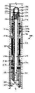
[0021] Referring now to FIG. 2, with continued reference to FIG. 1,
illustrated is a cross-sectional view of an exemplary wellbore isolation
device 200
that may employ one or more of the principles of the present disclosure,
according to one or more embodiments. The wellbore isolation device 200 may
be similar to or the same as the wellbore isolation device 116 of FIG. 1.
Accordingly, the wellbore isolation device 200 may be configured to be
extended
into and seal the wellbore 106 at a target location, and thereby prevent fluid
flow past the wellbore isolation device 200 for wellbore completion or
stimulation
operations. In some embodiments, as illustrated, the wellbore 106 may be lined
with the casing 114 or another type of wellbore liner or tubing in which the
wellbore isolation device 200 may suitably be set. In other embodiments,
however, the casing 114 may be omitted and the wellbore isolation device 200
may instead be set or otherwise deployed in an uncompleted or "open-hole"
environment.
[0022] The wellbore isolation device 200 is generally depicted and
described herein as a hydraulic fracturing plug or "frac" plug. It will be
appreciated by those skilled in the art, however, that the principles of this
disclosure may equally apply to any of the other aforementioned types of
casing
or borehole isolation devices, without departing from the scope of the
disclosure.
Indeed, the wellbore isolation device 200 may be any of a frac plug, a bridge
plug, a wellbore packer, a deployable baffle, a cement plug, a wiper plug, or
any
combination thereof in keeping with the principles of the present disclosure.
Where a flow passage is provided in the wellbore isolation device 200, as
.. discussed in detail below, the wellbore isolation device 200 may be any of
a frac
plug, a wellbore packer, a deployable packer, or any combination thereof.
[0023] As illustrated, the wellbore isolation device 200 may include a
ball cage 204 extending from or otherwise coupled to the upper end of a
mandrel 206. A sealing ball 208 (e.g., a frac ball) is disposed in the ball
cage
204 and the mandrel 206 defines a longitudinal central flow passage 210. The
7
CA 02955927 2017-01-20
WO 2016/032621
PCT/US2015/038624
mandrel 206 also defines a ball seat 212 at its upper end. One or more spacer
rings 214 (one shown) may be secured to the mandrel 206 and otherwise extend
thereabout. The spacer ring 214 provides an abutment, which axially retains a
set of upper slips 216a that are also positioned circumferentially about the
mandrel 206. As illustrated, a set of lower slips 216b may be arranged
distally
from the upper slips 216a. In other embodiments, the sealing ball 208 may be
dropped into the conveyance 118 (FIG. 1) to land on top of the wellbore
isolation
device 200 rather than being carried within the ball cage 204.
[0024] One or more slip wedges 218 (shown as upper and lower slip
wedges 218a and 218b, respectively) may also be positioned circumferentially
about the mandrel 206, and a packer assembly consisting of one or more
expandable or inflatable packer elements 220 may be disposed between the
upper and lower slip wedges 218a,b and otherwise arranged about the mandrel
206. It will be appreciated that the particular packer assembly depicted in
FIG.
2 is merely representative as there are several packer arrangements known and
used within the art. For instance, while three packer elements 220 are shown
in
FIG. 2, the principles of the present disclosure are equally applicable to
wellbore
isolation devices that employ more or less than three packer elements 220,
without departing from the scope of the disclosure.
[0025] A mule shoe 222 may be positioned at or otherwise secured to
the mandrel 206 at its lower or distal end. As will be appreciated, the lower
most portion of the wellbore isolation device 200 need not be a mule shoe 222,
but could be any type of section that serves to terminate the structure of the
wellbore isolation device 200, or otherwise serves as a connector for
connecting
the wellbore isolation device 200 to other tools, such as a valve, tubing, or
other
downhole equipment.
[0026] In some embodiments, a spring 224 may be arranged within a
chamber 226 defined in the mandrel 206 and otherwise positioned coaxial with
and fluidly coupled to the central flow passage 210. At one end, the spring
224
biases a shoulder 228 defined by the chamber 226 and at its opposing end the
spring 224 engages and otherwise supports the sealing ball 208. The ball cage
204 may define a plurality of ports 230 (three shown) that allow the flow of
fluids therethrough, thereby allowing fluids to flow through the length of the
wellbore isolation device 200 via the central flow passage 210.
8
CA 02955927 2017-01-20
,
,
WO 2016/032621
PCT/US2015/038624
[0027] As the wellbore isolation device 200 Is lowered into the wellbore
106, the spring 224 prevents the sealing ball 208 from engaging the ball seat
212. As a result, fluids may pass through the wellbore isolation device 200;
i.e.,
through the ports 230 and the central flow passage 210. The ball cage 204
retains the sealing ball 208 such that it is not lost during translation into
the
wellbore 106 to its target location. Once the wellbore isolation device 200
reaches the target location, a setting tool (not shown) of a type known in the
art
can be used to move the wellbore isolation device 200 from its unset position
(shown in FIG. 2) to a set position. The setting tool may operate via various
mechanisms to anchor the wellbore isolation device 200 in the wellbore 106
including, but not limited to, hydraulic setting, mechanical setting, setting
by
swelling, setting by inflation, and the like. In the set position, the slips
216a,b
and the packer elements 220 expand and engage the inner walls of the casing
114.
[0028] When it is desired to seal the wellbore 106 at the target location
with the wellbore isolation device 200, fluid is injected into the wellbore
106 and
conveyed to the wellbore isolation device 200 at a predetermined flow rate
that
overcomes the spring force of the spring 224 and forces the sealing ball 208
downwardly until it sealingly engages the ball seat 212. When the sealing ball
208 is engaged with the ball seat 212 and the packer elements 220 are in their
set position, fluid flow past or through the wellbore isolation device 200 in
the
downhole direction is effectively prevented. At that point, completion or
stimulation operations may be undertaken by injecting a treatment or
completion fluid into the wellbore 106 and forcing the treatment/completion
fluid
out of the wellbore 106 and into a subterranean formation above the wellbore
isolation device 200.
[0029] Following completion and/or stimulation operations, the wellbore
isolation device 200 must be removed from the wellbore 106 in order to allow
production operations to effectively occur without being excessively hindered
by
the emplacement of the wellbore isolation device 200. According to the present
disclosure, various components of the wellbore isolation device 200 may be
made of one or more slowly degrading or dissolving materials. The slowly
degrading materials provide more time between setting the wellbore isolation
device 200 and when a desired completion or stimulation operation is
undertaken, such as a hydraulic fracturing operation. Moreover,
slowly
9
CA 02955927 2017-01-20
WO 2016/032621
PCT/US2015/038624
degrading materials allow for acid treatments and acidified stimulation of the
wellbore 106. As will be appreciated, slowly degrading materials are typically
less expensive than rapidly degrading metals and, therefore, the wellbore
isolation device 200 may be less expensive as compared to wellbore isolation
devices made of rapidly dissolving or degrading materials.
[0030] As at least the mandrel 206 (and, in some embodiments, at
least the sealing ball 208, or any other component) are made of slowly
degradable metal materials, it may be desirable that the wellbore isolation
device 200 have a greater flow area or flow capacity through and/or around the
wellbore isolation device 200. According to the present disclosure, In some
embodiments the wellbore isolation device 200 may exhibit a large flow area or
flow capacity through and/or around the wellbore isolation device 200 so that
it
does not unreasonably impede, obstruct, or inhibit production operations while
the wellbore isolation device 200 degrades. As a result, production operations
may be undertaken while the wellbore isolation device 200 proceeds to dissolve
and/or degrade, and without creating a significant pressure restriction within
the
wellbore 106.
[0031] The wellbore isolation device 200 may provide a minimum
production flow area across the wellbore isolation device 200. As used herein
"production flow area across" the wellbore isolation device 200 refers to any
fluid
flow through and/or around the wellbore isolation device 200. In some
embodiments, the minimum production flow area across the wellbore isolation
device 200 may be a desired fraction of the total flow area of the wellbore
106
(i.e., the casing 114) at the location of the wellbore isolation device 200.
More
particularly, in at least one embodiment, the wellbore isolation device 200
may
exhibit a production flow area across the wellbore isolation device 200 that
is at
least 1/25 the total flow area of the wellbore 106 (i.e., the casing 114) at
the
location of the wellbore isolation device 200. In another embodiment, the
wellbore isolation device 200 may exhibit a production flow area across the
.. wellbore isolation device 200 that is at least 1/16 of the total flow area
of the
wellbore 106 at the location of the wellbore isolation device 200. The
production
flow area across the wellbore isolation device 200 may include any fluid flow
through the central flow passage 210 and any other flow paths through or
around the wellbore isolation device 200 that are not necessarily through the
central flow passage 210. In some embodiments, for instance, the wellbore
CA 02955927 2017-01-20
WO 2016/032621
PCT/US2015/038624
isolation device 200 may further include one or more conduits or flow channels
236 defined longitudinally through the mandrel 206 or other structural
portions
of the wellbore isolation device 200 through which fluids may flow during
production operations.
[0032] In other embodiments, the minimum production flow area of the
wellbore isolation device 200 may correspond to a desired ratio between the
inner and outer diameters of the wellbore isolation device 200. The term
"diameter" with reference to the minimum production flow area refers to the
diameter of the cross-sectional area of the wellbore isolation device 200 or
the
hydraulic diameter of a flow path (or a combined flow area) through the
wellbore
isolation device 200. The hydraulic diameter is defined as four times the
cross-
sectional area divided by the wetted perimeter of the cross section. As
illustrated, the wellbore isolation device 200 may exhibit an inner diameter
232
and an outer diameter 234. The inner diameter 232 may generally comprise the
diameter of the central flow passage 210, and the outer diameter 234 may
comprise the diameter of the wellbore isolation device 200 in the run-in or
unexpanded configuration. In at least one embodiment, the inner diameter 232
of the wellbore isolation device 200 may be at least 17% (Le., 1/6) of the
outer
diameter 234 of the wellbore isolation device 200. In another embodiment, the
inner diameter 232 of the wellbore isolation device 200 may be at least 25%
(Le., 1/4) of the outer diameter 234 of the wellbore isolation device 200. The
minimum 17% threshold may be calculated from the pressure drop across the
wellbore isolation device 200 as a function of the flow rate through the
central
flow passage 210 in applications having multiple wellbore isolation devices
positioned within the wellbore 106. Having the inner diameter 232 greater than
17% of the outer diameter 234 may increase the production flow area through
the central flow passage 210 and thereby provide a lower pressure drop across
the wellbore isolation device 200. The upper limit of the inner diameter 232
may be dependent on the structural limitations of the wellbore isolation
device
200 and, more particularly, the structural limitations of the mandrel 206. For
instance, the inner diameter 232 may be any diameter as long as the mandrel
206 remains able to adequately hold or maintain pressure loads that may be
assumed during downhole operation.
[0033] In yet other embodiments, the minimum production flow area of
the wellbore isolation device 200 may need to be larger than the
aforementioned
11
CA 02955927 2017-01-20
WO 2016/032621
PCT/US2015/038624
two options. With a larger number of wellbore isolation devices, with higher
production flow rates, or with lower acceptable pressure drop, the minimum
production flow area should be larger to achieve a lower pressure drop of the
fluid across the wellbore isolation device 200. In these cases, the fraction
of the
total flow area should be larger, or the inner diameter 232 of the wellbore
isolation device 200 should be a higher fraction of the outer diameter 234.
For
example, in at least one embodiment, a large number of wellbore isolation
devices (e.g., greater than twenty-nine) may be required. In such
embodiments, the minimum production flow area of the wellbore isolation device
200 may be achieved by having a production flow area through and/or around
the wellbore isolation device 200 that is at least 1/9 of the total flow area
of the
wellbore 106 (i.e., the casing 114) at the location of the wellbore isolation
device
200, or where the inner diameter 232 of the wellbore isolation device 200 is
at
least 33% (i.e., 1/3) of the outer diameter 234. In another embodiment, an
even larger number of wellbore isolation devices (e.g., greater than forty-
nine)
may be required for a specific application. In such embodiments, the minimum
production flow area of the wellbore isolation device 200 may be achieved by
having a production flow area through and/or around the wellbore isolation
device 200 that Is at least 1/6 of the total flow area of the wellbore 106 at
the
location of the wellbore isolation device 200, or where the inner diameter 232
of
the wellbore isolation device 200 is at least 41% of the outer diameter 234.
[0034] According to the present disclosure, at least the mandrel 206
(and, in some embodiments, at least the sealing ball 208, or any other
component) may be made of or otherwise comprise a degradable metal material
configured to slowly degrade or dissolve within a wellbore environment. In
other
embodiments, other components of the wellbore isolation device 200 may also
be made of or otherwise comprise a degradable metal material including, but
not
limited to, the upper and lower slips 216a,b, the upper and lower slip wedges
218a,b, and the mule shoe 222. In addition to the foregoing, other components
of the wellbore isolation device 200 that may be made of or otherwise comprise
a degradable metal material include extrusion limiters and shear pins
associated
with the wellbore isolation device 200. The foregoing structural elements or
components of the wellbore isolation device 200 are collectively referred to
herein as "the components" in the following discussion. In some embodiments,
as discussed below, the sealing ball 208 may be composed of a degradable
12
CA 02955927 2017-01-20
WO 2016/032621
PCT/US2015/038624
metal material, a degradable elastomer, a degradable glass material, and any
combination thereof. In some embodiments, as discussed in greater detail
below, the packer element 220 is composed of a non-degradable or minimally
degradable elastomer, or a degradable elastomer. As used herein, the term
"minimally degradable" refers to degradation of no more than about 50% by
volume of the material in a wellbore environment.
[0035] The degradable metal material, degradable elastomer, and/or
degradable glass material (collectively simply "degradable substances") for
use
in forming components of the wellbore isolation device 200 may degrade, at
least in part, in the presence of an aqueous fluid (e.g., a treatment fluid),
a
hydrocarbon fluid (e.g., a produced fluid in the formation or a treatment
fluid),
an elevated temperature, and any combination thereof. That is, the degradable
substances may wholly degrade or partially degrade. The aqueous fluid that
may degrade the degradable substances may include, but is not limited to,
fresh
water, saltwater (e.g., water containing one or more salts dissolved therein),
brine (e.g., saturated salt water), seawater, or combinations thereof.
Accordingly, the aqueous fluid may comprise ionic salts. The aqueous fluid may
come from the wellbore 106 itself (i.e., the subterranean formation) or may be
introduced by a wellbore operator. The hydrocarbon fluid may include, but is
not
limited to, crude oil, a fractional distillate of crude oil, a fatty
derivative of an
acid, an ester, an ether, an alcohol, an amine, an amide, or an imide, a
saturated hydrocarbon, an unsaturated hydrocarbon, a branched hydrocarbon, a
cyclic hydrocarbon, and any combination thereof. The elevated temperature
may be above the glass transition temperature of the degradable substance,
such as when the degradable elastomer is a thiol-based polymer, or may be a
temperature greater than about 60 C (140 F).
[0035] The degradable substances forming at least a portion of the
wellbore isolation device 200 may degrade by a number of mechanisms. For
example, the degradable substances may degrade by swelling, dissolving,
undergoing a chemical change, undergoing thermal degradation in combination
with any of the foregoing, and any combination thereof. Degradation by swell
involves the absorption by the degradable substance of a fluid in the wellbore
environment such that the mechanical properties of the degradable substance
degrade. That is, the degradable substance continues to absorb the fluid until
its mechanical properties are no longer capable of maintaining the integrity
of
13
CA 02955927 2017-01-20
WO 2016/032621
PCT/US2015/038624
the degradable substance and it at least partially falls apart. In some
embodiments, a degradable substance may be designed to only partially
degrade by swelling in order to ensure that the mechanical properties of the
component of the wellbore isolation device 200 formed from the degradable
substance is sufficiently capable of lasting for the duration of the specific
operation in which it is utilized. Degradation by dissolving involves use of a
degradable substance that is soluble or otherwise susceptible to a fluid in
the
wellbore environment (e.g., an aqueous fluid or a hydrocarbon fluid), such
that
the fluid is not necessarily incorporated into the degradable substance (as is
the
case with degradation by swelling), but becomes soluble upon contact with the
fluid. Degradation by undergoing a chemical change may involve breaking the
bonds of the backbone of the degradable substance (e.g., polymer backbone) or
causing the bonds of the degradable substance to crosslink, such that the
degradable substance becomes brittle and breaks into small pieces upon contact
with even small forces expected irk the wellbore environment. Thermal
degradation involves a chemical decomposition due to heat, such as the heat
present in a wellbore environment. Thermal degradation of some degradable
substances described herein may occur at wellbore environment temperatures of
greater than about 93 C (or about 200 F), or greater than about 50 C (or about
.. 122 F). Each degradation method may work in concert with one or more of the
other degradation methods, without departing from the scope of the present
disclosure.
[0037] Referring now to the slowly degradable metal material of the
present disclosure, the rate of degradation of the degradable metal material
may
depend on a number of factors including, but not limited to, the type of
degradable metal material selected and the conditions of the wellbore
environment. As used herein, a "slowly degradable metal material" (also
referred to simply as "degradable metal material" herein) may refer to the
rate
of dissolution of the degradable metal material, and the rate of dissolution
may
correspond to a rate of material loss at a particular temperature and within
particular wellbore conditions. For instance, in at least one embodiment, a
slowly degradable metal material may comprise a material that exhibits a
degradation rate in an amount in the range of a lower limit of 0.01 milligrams
per square centimeters (mg/cm2) to about 10 mg/cm2 per hour at a temperature
of 200 F (93.3 C) while exposed to a 15% potassium chloride (KCl) solution,
14
CA 02955927 2017-01-20
WO 2016/032621
PCT/US2015/038624
encompassing any value and subset therebetween. For example,
the
degradation rate may be about 0.01 mg/cm2 to about 2.5 mg/cm2, or about 2.5
mg/cm2 to about 5 mg/cm2, or about 5 mg/cm2 to about 7.5 mg/cm2, or about
7.5 mg/cm2 to about 10 mg/cm2 per hour at a temperature of 200 F (93.3 C)
while exposed to a 15% potassium chloride (KCI) solution, encompassing any
value and subset therebetween. In other instances, a slowly degradable
material may comprise a material that loses about 0.1% to about 10% of its
total mass per day at 200 F (93.3 C) in 15% KCI solution, encompassing any
value and subset therebetween. For example, in some embodiments the
degradable metal material may lose about 0.1% to about 2.5%, or about 2.5%
to about 5%, or about 5% to about 7.5%, or about 7.5% to about 10% of its
total mass per day at 200 F (93.3 C) in 15% KCI solution, encompassing any
value and subset therebetween. Each of these values representing the slowly
degradable metal material is critical to the embodiments of the present
disclosure and may depend on a number of factors including, but not limited
to,
the type of degradable metal material, the wellbore environment, and the like.
[0038] In some embodiments, the degradation rate of the degradable
metal material may be somewhat faster, such that the degradable metal
material exhibits a degradation rate in an amount of greater than about 10
mg/cm2 per hour at 200 F (93.3 C) in 15% KCI solution. In other embodiments,
the degradable metal material exhibits a degradation rate such that greater
than
about 10% of its total mass is lost per day at 200 F (93.3 C) in 15% KCl
solution.
[0039] The degradation of the degradable metal material may be in the
range of from about 5 days to about 40 days, encompassing any value or subset
therebetween. For example, the degradation may be about 5 days to about 10
days, or about 10 days to about 20 days, or about 20 days to about 30 days, or
about 30 days to about 40 days, encompassing any value and subset
therebetween. Each of these values representing the slowly degradable metal
material is critical to the embodiments of the present disclosure and may
depend
on a number of factors including, but not limited to, the type of degradable
metal material, the wellbore environment, and the like.
[0040] Suitable slowly degradable metal materials that may be used in
accordance with the embodiments of the present disclosure include galvanically-
corrodible or degradable metals and metal alloys. Such metals and metal alloys
CA 02955927 2017-01-20
WO 2016/032621
PCT/US2015/038624
may be configured to degrade via an electrochemical process in which the
galvanically-corrodible metal corrodes in the presence of an electrolyte
(e.g.,
brine or other salt-containing fluids present within the wellbore 106). As
used
herein, an "electrolyte" is any substance containing free ions (i.e., a
positively or
negatively charged atom or group of atoms) that make the substance
electrically
conductive. The electrolyte can be selected from the group consisting of,
solutions of an acid, a base, a salt, and combinations thereof. A salt can be
dissolved in water, for example, to create a salt solution. Common free ions
in
an electrolyte include, but are not limited to, sodium (Na), potassium (K4),
calcium (Ca24), magnesium (Mg24), chloride (Cr), bromide (EV) hydrogen
phosphate (HP042-), hydrogen carbonate (HCO3"), and any combination thereof.
Preferably, the electrolyte contains chloride ions. The electrolyte can be a
fluid
that is introduced into the wellbore 106 or a fluid emanating from the
wellbore
106, such as from a surrounding subterranean formation (e.g., the formation
108 of FIG. 1).
[0041] Suitable degradable metal materials include, but are not limited
to, gold, gold-platinum alloys, silver, nickel, nickel-copper alloys, nickel-
chromium alloys, copper, copper alloys (e.g., brass, bronze, etc.), chromium,
tin, aluminum, aluminum alloys, iron, zinc, magnesium, magnesium alloys,
beryllium, any alloy of the aforementioned materials, and any combination
thereof.
[0042] Suitable magnesium alloys include alloys having magnesium at a
concentration in the range of from about 40% to about 99% by weight of the
magnesium, encompassing any value and subset therebetween. In some
embodiments, the magnesium concentration may be in the range of about 40%
to about 99%, 70% to about 98%, and preferably about 80% to about 95% by
weight of the magnesium alloy, encompassing any value and subset
therebetween. Each of these values is critical to the embodiments of the
present
disclosure and may depend on a number of factors including, but not limited
to,
the type of magnesium alloy, the desired degradability of the magnesium alloy,
and the like.
[0043] Magnesium alloys comprise at least one other ingredient besides
the magnesium. The other ingredients can be selected from one or more
metals, one or more non-metals, or a combination thereof. Suitable metals that
may be alloyed with magnesium include, but are not limited to, lithium,
sodium,
16
CA 02955927 2017-01-20
WO 2016/032621
PCT/US2015/038624
potassium, rubidium, cesium, beryllium, calcium, strontium, barium, aluminum,
gallium, indium, tin, thallium, lead, bismuth, scandium, titanium, vanadium,
chromium, manganese, iron, cobalt, nickel, copper, zinc, yttrium, zirconium,
niobium, molybdenum, ruthenium, rhodium, palladium, praseodymium, silver,
lanthanum, hafnium, tantalum, tungsten, terbium, rhenium, osmium, iridium,
platinum, gold, neodymium, gadolinium, erbium, oxides of any of the foregoing,
and any combinations thereof.
[0044] Suitable non-metals that may be alloyed with magnesium
include, but are not limited to, graphite, carbon, silicon, boron nitride, and
combinations thereof. The carbon can be in the form of carbon particles,
fibers,
nanotubes, fullerenes, and any combination thereof. The graphite can be in the
form of particles, fibers, graphene, and any combination thereof. The
magnesium and its alloyed ingredient(s) may be in a solid solution and not in
a
partial solution or a compound where inter-granular inclusions may be present.
In some embodiments, the magnesium and its alloyed ingredient(s) may be
uniformly distributed throughout the magnesium alloy but, as will be
appreciated, some minor variations in the distribution of particles of the
magnesium and its alloyed ingredient(s) can occur. In other embodiments, the
magnesium alloy is a sintered construction.
[0045] In some embodiments, the magnesium alloy may have a yield
stress in the range of from about 20000 pounds per square inch (psi) to about
50000 psi, encompassing any value and subset therebetween. For example, in
some embodiments, the magnesium alloy may have a yield stress of about
20000 psi to about 30000 psi, or about 30000 psi to about 40000 psi, or about
40000 psi to about 50000 psi, encompassing any value and subset
therebetween.
[0046] Suitable aluminum alloys include alloys having aluminum at a
concentration in the range of from about 40% to about 99% by weight of the
aluminum alloy, encompassing any value and subset therebetween. For
example, suitable magnesium alloys may have aluminum concentrations of
about 40% to about 50%, or about 50% to about 60%, or about 60% to about
70%, or about 70% to about 80%, or about 80% to about 90%, or about 90%
to about 99% by weight of the aluminum alloy, encompassing any value and
subset therebetween. Each of these values is critical to the embodiments of
the
present disclosure and may depend on a number of factors including, but not
17
CA 02955927 2017-01-20
WO 2016/032621
PCT/US2015/038624
limited to, the type of aluminum alloy, the desired degradability of the
aluminum
alloy, and the like.
[0047] The aluminum alloys may be wrought or cast aluminum alloys
and comprise at least one other ingredient besides the aluminum. The other
ingredients can be selected from one or more any of the metals, non-metals,
and combinations thereof described above with reference to magnesium alloys,
with the addition of the aluminum alloys additionally being able to comprise
magnesium.
[0048] Suitable degradable metal materials for use in the embodiments
described herein also include micro-galvanic metals or materials, such as
solution-structured galvanic materials. An example of a solution-structured
galvanic material is a magnesium alloy containing zinc (Zn), where different
domains within the alloy contain different percentages of Zn. This leads to a
galvanic coupling between these different domains, which causes micro-galvanic
corrosion and degradation. Micro-galvanically corrodible magnesium alloys
could
also be solution structured with other elements such as zinc, aluminum,
manganese, nickel, cobalt, calcium, iron, carbon, tin, silver, copper,
titanium,
rare earth elements, etc. Examples of solution-structured micro-galvanically-
corrodible magnesium alloys include ZK60, which includes 4.5% to 6.5% zinc,
minimum 0.25% zirconium, 0% to 1% other, and balance magnesium; AZ80,
which includes 7.5% to 9.5% aluminum, 0.2% to 0.8% zinc, 0.12% manganese,
0.015% other, and balance magnesium; and AZ31, which includes 2.5% to
3.5% aluminum, 0.5% to 1.5% zinc, 0.2% manganese, 0.15% other, and the
balance magnesium. Each of these examples is % by weight of the metal alloy.
In some embodiments, "other" may include unknown materials, impurities,
additives, and any combination thereof.
[0049] In some embodiments, the slowly degradable metal material
forming at least the mandrel 206 (and, in some embodiments, at least the
sealing ball 208, or any other component) of a wellbore isolation device 200
may
comprise dissimilar metals that generate a galvanic coupling that either
accelerates or decelerates the degradation rate of the mandrel 206, or of
another component of the wellbore isolation device 200 that is at least
partially
composed of a degradable substance, whether a degradable metal material or a
degradable non-metal material (e.g., a degradable elastomer), such as the
packer element 220. As will be appreciated, such embodiments may depend on
18
CA 02955927 2017-01-20
WO 2016/032621
PCT/1JS2015/038624
where the dissimilar metals lie on the galvanic series. In at least
one
embodiment, a galvanic coupling may be generated by embedding or attaching a
cathodic substance or piece of material into an anodic component. For
instance,
the galvanic coupling may be generated by dissolving aluminum in gallium. A
galvanic coupling may also be generated by using a sacrificial anode coupled
to
the degradable material. In such embodiments, the degradation rate of the
degradable metal material may be decelerated until the sacrificial anode is
dissolved or otherwise corroded away. As an example, the mandrel 206 and the
sealing ball 208 may both be composed of a degradable metal material, and the
mandrel 206 may be a more electronegative material than the sealing ball 208.
In such an embodiment, the galvanic coupling between the mandrel 206 and the
sealing ball 208 may cause the mandrel 206 to act as an anode and degrade
before the sealing ball 208. Once the mandrel 206 has degraded, the sealing
ball 208 would dissolve or degrade independently.
[0050] In some embodiments, the density of the component of the
wellbore isolation device 200 composed of a degradable metal material (e.g.,
at
least the mandrel 206), as described herein, may exhibit a density that is
relatively low. The low density may prove advantageous in ensuring that the
wellbore isolation device 200 may can be placed in extended-reach wellbores,
such as extended-reach lateral wellbores. As will be appreciated, the more
components of the wellbore isolation device composed of the degradable metal
material having a low density, the lesser the density of the wellbore
isolation
device 200 as a whole. In some embodiments, the degradable metal material is
a magnesium alloy or an aluminum alloy and may have a density less than 3
g/cm3 or less than 2 g/cm3. In other embodiments where the degradable metal
material is a material that is lighter than steel, the density of the may be
less
than 5 g/cm3. By way of example, the inclusion of lithium in a magnesium alloy
can reduce the density of the alloy.
[0051] In some embodiments, the packer element 220 of the wellbore
isolation device 200 may be composed of an elastomer that is sufficiently
resilient (i.e., elastic) to provide a fluid seal between two portions of a
wellbore
section. In a preferred embodiment, the packer element 220 is composed of a
degradable elastomer. It may be desirable that the amount of degradation is
capable of causing the packer element 220 to no longer maintain a fluid seal
in
the wellbore capable of maintaining differential pressure. However, because
the
19
CA 02955927 2017-01-20
WO 2016/032621 PCT/US2015/038624
mandrel 206 and the sealing ball 208 are additionally composed of a degradable
substance, the degradation of at least the three components may not
necessitate that the packer element 220 degrade to the point of breaking the
fluid seal on its own.
[0052] The degradation rate of
the degradable elastomer for forming
the packer element 220 may be accelerated, rapid, or normal, as defined
herein.
Accelerated degradation may be in the range of from about 2 hours to about 36
hours, encompassing any value or subset therebetween. Rapid degradation may
be in the range of from about 36 hours to about 14 days, encompassing any
value or subset therebetween. Normal degradation may be in the range of from
about 14 days to about 120 days, encompassing any value or subset
therebetween. Accordingly, the degradation may be between about 120 minutes
to about 120 days. For example, the degradation of the degradable elastomer
may be about 2 hours to about 30 days, or about 30 days to about 60 days, or
about 60 days to about 90 days, or about 90 days to about 120 days,
encompassing any value and subset therebetween. Each of these values is
critical and depending on a number of factors including, but not limited to,
the
type of degradable elastomer selected, the conditions of the wellbore
environment, and the like.
[0053] The degradable elastomer
forming at least a portion of the
packer element 220 may be a material that is at least partially degradable in
a
wellbore environment including, but not limited to, a polyurethane rubber
(e.g.,
cast polyurethanes, thermoplastic polyurethanes, polyethane polyurethanes); a
polyester-based polyurethane rubber (e.g., lactone polyester-based
thermoplastic polyurethanes); a polyether-based polyurethane rubber; a thiol-
based polymer (e.g., 1,3,5,-triacryloylhexahydro-1,3,5-triazine); a thiol-
epoxy
polymer (e.g., having an epoxide functional group, such as bisphenol-A
diglycidyl ether, triglycidylisocyanurate, and/or trimethylolpropane
triglycidyl
ether); a hyaluronic acid rubber; a polyhydroxobutyrate rubber; a polyester
elastomer; a polyester amide elastomer; a starch-based resin (e.g., starch-
poly(ethylene-co-vinyl alcohol), a starch-polyvinyl alcohol, a starch-
polylactic
acid, starch-polycaprolactone, starch-poly(butylene succinate), and the like);
a
polyethylene terephtha late polymer; a polyester thermoplastic (e.g.,
polyether/ester copolymers, polyester/ester copolymers); a polylactic acid
polymer; a polybutylene succinate polymer; a polyhydroxy alkanoic acid
CA 02955927 2017-01-20
WO 2016/032621 PCT/US2015/038624
polymer; a polybutylene terephthalate polymer; a polysaccharide; chitin;
chitosan; a protein; an aliphatic polyester; poly(E-caprolactone); a
poly(hydroxybutyrate); poly(ethyleneoxide); poly(phenyllactide); a poly(amino
acid); a poly(orthoester); polyphosphazene; a polylactide; a polyglycolide; a
poly(anhydride) (e.g., poly(adipic anhydride), poly(suberic anhydride),
poly(sebacic anhydride), poly(dodecanedioic anhydride), poly(maleic
anhydride),
and poly(benzoic anhydride), and the like); a polyepichlorohydrin; a copolymer
of ethylene oxide/polyepichlorohydrin; a terpolymer of
epichlorohydrin/ethylene
oxide/allyl glycidyl ether; copolymers thereof; terpolymers thereof; and any
combination thereof.
[0054] In some embodiments, the
degradable elastomer selected for
use in forming the packer element 220 may be a polyurethane rubber, a
polyester-based polyurethane rubber, or a polyether-based polyurethane rubber
(collectively simply "polyurethane-based rubbers). These polyurethane-based
rubbers degrade in water through a hydrolytic reaction, although other
degradation methods may also affect the degradability of the polyurethane-
based rubbers. As used herein, the term "hydrolytic reaction," and variants
thereof (e.g., "hydrolytic degradation") refers to the degradation of a
material by
cleavage of chemical bonds in the presence of (e.g., by the addition of) an
aqueous fluid. Polyurethane-based rubbers traditionally are formed by reacting
a polyisocyanate with a polyol. In the embodiments described herein, although
non-limiting, the polyol for forming a polyurethane-based rubber may be a
natural oil polyol, a polyester polyol (e.g., polybutadienes (e.g.,
polybutanediol
adipate), polycaprolactones, polycarbonates, and the like), or a polyether
polyol
(e.g., polytetramethylene ether glycol, polyoxypropylene-glycol,
polyoxyethylene
glycol, and the like). Because polyether polyols are typically hydrolytically
more
reactive than polyester polyols and natural oil polyols, polyether polyols may
be
preferred, particularly when the degradation of the degradable elastomer is
solely based on aqueous fluid contact and not additionally on other
degradation
stimuli. However, either polyol may be used to form the polyurethane-based
rubber for use as the degradable elastomer described herein, and each is
critical
to the disclosed embodiments, as the amount of desired degradation over time
may depend on a number of factors including the conditions of the subterranean
formation, the subterranean formation operation being performed, and the like.
21
CA 02955927 2017-01-20
WO 2016/032621 PCT/US2015/038624
Combinations of these polyols may also be used, without departing from the
scope of the present disclosure.
[0055] Accordingly, the rate of
hydrolytic degradation of a
polyurethane-based rubber for use as the degradable elastomers described
herein may be adjusted and controlled based on the order of the polyol
addition,
as well as the polyol properties and quantities. As an example, in some
embodiments, the amount of polyol is included in an amount in the range of
from about 0.25 to about 2 stoichiometric ratio of the polyisocyanate in the
polyurethane-based rubber, encompassing any value and subset therebetween.
For example, the polyol may be included in an amount of about 0.25 to about
0.5, or about 0.5 to about 1, or about 1 to about 1.5, or about 1.5 to about 2
stoichiometric ratio of the polyisocyanate in the polyurethane-based rubber,
encompassing any value and subset therebetween. Each of these values is
critical to the embodiments described herein and may depend on a number of
factors including, but not limited to, the desired hydrolytic degradation
rate, the
type of polyol(s) selected, the type of subterranean formation being
performed,
and the like.
[0056] In some embodiments, where
the degradable elastomer
selected is a polyurethane-based rubber for use in forming the packer element
220, the inclusion of a low functionality initiator may impart flexibility to
thereto.
Such low functionality initiators may include, but are not limited to
dipropylene
glycol, glycerine, sorbitol/water solution, and any combination thereof. As
used
herein, the term "low functionality initiator," and grammatical variants
thereof,
refers to the average number of isocyanate reactive sites per molecule of in
the
range of from about 1 to about 5. These low functionality initiators impart
flexibility to the packer element 220 and may be included in the polyurethane-
based rubbers described herein in an amount in the range of from about 1% to
about 50% by weight of the polyol in the polyurethane-based rubber,
encompassing any value and subset therebetween. For example, the low
functionality initiator(s) may be included in the polyurethane-based rubbers
in
an amount of about 1% to about 12.5%, or about 12.5% to about 25%, or
about 25% to about 37.5%, or about 37.5% to about 50% by weight of the
polyol in the polyurethane-based rubber, encompassing any value and subset
therebetween. Additionally, in some embodiments, higher molecular weight
polyols for use in forming the polyurethane-based rubbers described herein may
22
CA 02955927 2017-01-20
WO 2016/032621
PCMS2015/038624
impart flexibility to the packer element 220 described herein. For example, in
some embodiments, the molecular weight of the selected polyols may be in the
range of from about 200 Da!tons (Da) to about 20000 Da, encompassing any
value and subset therebetween. For example, the molecular weight of the
polyols may be about 200 Da to about 5000 Da, or about 5000 Da to about
10000 Da, or about 10000 Da to about 15000 Da, or about 15000 Da to about
20000 Da, encompassing any value and subset therebetween. Each of these
values is critical to the embodiments described herein and may depend on a
number of factors including, but not limited to, the desired flexibility of
the
degradable elastomer (and thus, e.g., the packer element 220), the type of
subterranean formation operation being performed, the conditions in the
subterranean formation, and the like.
[0057] In some embodiments, the degradable elastomer described
herein may be formed from a thiol-based polymer. As used herein, the term
"thiol" is equivalent to the term "sulfhydryl." The thiol-based polymer may
comprise at least one thiol functional group. In some embodiments, the thiol-
based polymer may comprise thiol functional groups in the range of from about
1 to about 22, encompassing every value and subset therebetween. For
example, the thiol-based polymer may comprise thiol functional groups in an
amount of about 1 to about 5, or 5 to about 10, or 10 to about 15, or 15 to
about 20, or 20 to about 22, encompassing any value and subset therebetween.
In other embodiments, the thiol-based polymer may comprise even a greater
number of thiol functional groups. Each of these values is critical to the
embodiments of the present disclosure and may depend on a number of factors
including, but not limited to, the desired degradation rate, the desired
degradation process, and the like.
[0058] The thiol-based polymer may be, but is not limited to, a
thiol-ene reaction product, a thiol-yne reaction product, a thiol-epoxy
reaction
product, and any combination thereof. The thiol-based polymers, whether the
reaction product of thiol-ene, thiol-yne, or thiol-epoxy, may be referred to
herein
as generally being the reaction product of a thiol functional group and an
unsaturated functional group, and may be formed by click chemistry. The thiol
functional group is an organosulfur compound that contains a carbon-bonded
sulfhydryl, represented by the formula -C-SH or R-SH, where R represents an
alkane, alkene, or other carbon-containing group of atoms.
23
CA 02955927 2017-01-20
,
WO 2016/032621 PCT/US2015/038624
[0059] Thiol-ene reactions may be characterized as the sulfur
version of a hydrosilylation reaction. The thiol-ene reaction product may be
formed by the reaction of at least one thiol functional group with a variety
of
unsaturated functional groups including, but not limited to, a maleimide, an
acrylate, a norborene, a carbon-carbon double bond, a silane, a Michael-type
nucleophilic addition, and any combination thereof. As used herein, the term
"Michael-type nucleophilic addition," and grammatical variants thereof, refers
to
the nucleophilic addition of a carbanion or another nucleophile to an 0,0-
unsaturated carbonyl compound, having the general structure (0=C)-Ca=C13-.
An example of a suitable thiol-ene reaction product may include, but is not
limited to, 1,3,5,-triacryloylhexahydro-1,3,5-triazine. Examples of suitable
thiol-
ene/silane reaction products that may be used in forming at least a portion of
the downhole tool 100 (FIG. 1) or component thereof include, but are not
limited to, the following Formulas 1-6:
CiH3N ____________________ \ / __ NH3CI
_______________________________ S S
\ /
\ /
/
/Si\
\ \s
[0060] ____ CiH3N __ / S NH3C1
Formula 1
24
CA 02955927 2017-01-20
,
WO 2016/032621 PCT/US2015/038624
HO OH HO OH
\ (S S /
\ /
\/
Si
/\
/ \
/ S S
\
[0061] HO OH HO OH
Formula 2
0 0
Me0
( __ S S __ > ______ OMe
\ /
\ /
Si
/\
/ \
S
Me0 S __ \
OMe
[0062] 0 01
Formula 3
(Me0)3Si \ ,Si(OMe)3
\ ____________________________________ S S __ /
\ /
\/
/ /Si\_....\
/S S¨\
/ \
[0063] (Me0)3Si Si(OMe)3
Formula 4
CA 02955927 2017-01-20
WO 2016/032621 PCT/US2015/038624
HOOC __________________________________________________ COOH
HOOC COOH
Si
HOOC COOH
[0064] __________________________ HOOC S
COOH
Formula 5
Na03S
jS03Na
\¨S
S
[0065] Na03S SO3Na
Formula 6
[0066] The thiol-yne reaction products may be characterized by an
organic addition reaction between a thiol functional group and an alkyne, the
alkyne being an unsaturated hydrocarbon having at least one carbon-carbon
triple bond. The addition reaction may be facilitated by a radical initiator
or UV
irradiation and proceeds through a sulfanyl radical species. The reaction may
also be amine-mediated, or transition-metal catalyzed.
[0067] The thiol-epoxy reaction products may be prepared by a
thiol-ene reaction with at least one epoxide functional group. Suitable
epoxide
functional groups may include, but are not limited to, a glycidyl ether, a
glycidyl
amine, or as part of an aliphatic ring system. Specific examples of epoxide
functional groups may include, but are not limited to, bisphenol-A diglycidyl
ether, triglycidylisocyanurate, trimethylolpropane triglycidyl ether, and any
combination thereof. The thiol-epoxy reaction products may proceed by one or
more of the mechanisms presented below; however, other mechanisms may also
be used without departing from the scope of the present disclosure:
26
CA 02955927 2017-01-20
WO 2016/032621 PCT/US2015/038624
R2 R2
R1¨SH App.-- R1¨S- + NI+H
Rf \R4 p \ p
[0068] ..3
Mechanism 1
o R5 .õ...re=,,s,,R,
-- R,s-
R5 _____________________________
[0069] 0-
Mechanism 2
R2 R2
R5 R1 + R5 y"\Ri
N+H ¨)111"-
pp
0 OH .3
[0070] \F24
Mechanism 3
R2 R2
0
N + ___________________________________ N+ A
R( \ R4 __________________________________________ R5
[0071] R3 R4
Mechanism 4
R2 R5 /N14:\ /o\ R5 R1¨SH +
\
[0072] R3 R4 OH R( R4
Mechanism 5
R2 R5 R6 R2
S f I
NI+\. A ¨11101-
R ____________________________ + R6¨OH 3/ R5
OH R(N \R4
[0073]
Mechanism 6
[0074] As mentioned above, the thiol-based polymer may comprise
at least one thiol functional group and at least one degradable functional
group.
Such degradable functional groups may include, but are not limited to, one or
more of a degradable monomer, a degradable oligomer, or a degradable
polymer. Specific examples of degradable functional groups may include, but
are not limited to, an acrylate, a lactide, a lactone, a glycolide, an
anhydride, a
lactam, an allyl, a polyethylene glycol, a polyethylene glycol-based hydrogel,
an
aerogel, a poly(lactide), a poly(glycolic acid), a poly(vinyl alcohol), a
poly(N-
isopropylacrylamide), a poly(e-caprolactone, a poly(hydroxybutyrate), a
polyanhydride, an aliphatic polycarbonate, an aromatic polycarbonate, a
poly(orthoester), a poly(hydroxyl ester ether), a poly(orthoester), a
poly(amino
27
CA 02955927 2017-01-20
,
WO 2016/032621 PCT/US2015/038624
acid), a poly(ethylene oxide), a polyphosphazene, a poly(phenyllactide), a
poly(hydroxybutyrate), a dextran, a chitin, a cellulose, a protein, an
aliphatic
polyester, and any combination thereof.
[0075] In some embodiments, the
thiol-based polymer comprises at
least one polyethylene glycol-based hydrogel, such as one formed by a four-arm
polyethylene glycol norbornene that is crosslinked with dithiol containing
crosslinkers to form a chemically crosslinked hydrogel to impart swelling
properties. The swelling properties of such a hydrogel may vary depending on a
number of factors including, but not limited to, network density, the degree
of
crosslinking, and any combination thereof. In some embodiments, the degree of
crosslinking may be desirably increased in order to achieve a higher tensile
modulus and reduced swelling percentage.
[0076] The sealing ball 208 may
be composed of the degradable
metal material or the degradable elastomer described above. For example, the
sealing ball 208 may be made of polyglycolic acid (PGA) and/or polylactic acid
(PLA). In other embodiments, the sealing ball 208 may be composed of a
degradable glass material including, but not limited to, glass polyalkenoate,
borate glass polyalkenoate, calcium phosphate glass, polylactic acid/calcium
phosphate glass, phosphate glass, silica glass, and any combination thereof.
Additionally, the sealing ball 208 may be any combination of the degradable
metal material, the degradable elastomer, and/or the degradable glass
material,
and may additionally comprise an additive such as those discussed below (e.g.,
thermoplastic addition, reinforcing agent addition, and the like), without
departing from the scope of the present disclosure.
[0077] Any other component of the
wellbore isolation device 200
may additionally be composed of the degradable metal material, the degradable
elastomer, or the degradable glass material described herein. Generally, the
degradable metal material and the degradable glass material are rigid and
provide structure, whereas the degradable elastomer is resilient (i.e.,
elastic),
which will dictate the particular components of the wellbore isolation device
200
that are composed of either of these materials.
Additionally, in other
embodiments, any component of the wellbore isolation device 200 may be a
degradable non-metal material. Any non-degradable material (e.g., metals,
plastics, glass, and the like) may additionally be used to form a component of
the wellbore isolation device 200.
28
CA 02955927 2017-01-20
WO 2016/032621 PCT/US2015/038624
[0078] In some embodiments, the
degradable substance(s) forming
one or more components of the wellbore isolation device 200 may have a
thermoplastic polymer embedded therein. In some instances, the degradable
elastomer is itself a thermoplastic, in which case a different thermoplastic
polymer may be embedded therein, in accordance with the embodiments
described herein. The
thermoplastic polymer may modify the strength,
resiliency, or modulus of a component of the wellbore isolation device 200
(e.g.,
the packer element 220) and may also control the degradation rate thereof.
Suitable thermoplastic polymers may include, but are not limited to,
polypropylene, an aliphatic polyester (e.g., polyglycolic acid, polylactic
acid,
polycaprolactone, polyhydroxyalkanoate,
polyhydroxyalkanoiate,
polyhydroxybutyrate, polyethylene adipate, polybutylene succinate, poly(lactic-
co-glycolic) acid, poly(3-hydroxybutyrate-co-3-hyroxyvalerate, polycarbonate,
and the like), and any combination thereof. In some situations, as stated
above,
the degradable substance may be a thermoplastic, which may be combined with
one or more degradable substances (in combination) or a thermoplastic listed
above. The amount of thermoplastic polymer that may be embedded in the
degradable substance forming may be any amount that confers a desirable
quality (e.g., elasticity) without affecting the desired amount of
degradation. In
some embodiments, the thermoplastic polymer may be included in an amount in
the range of from about 1% to about 91% by weight of the degradable
substance, encompassing any value or subset therebetween. For example, the
thermoplastic polymer may be included in an amount of about 1% to about
25%, or about 25% to about 50%, or about 50% to about 75%, or about 75%
to about 91% by weight of the degradable substance, encompassing any value
or subset therebetween. Each of these values is critical to the embodiments
described herein and may depend on a number of factors including, but not
limited to, the desired flexibility of the degradable substance, the desired
degradation rate of the degradable substance, the conditions of the
subterranean formation, the subterranean formation operation being performed,
and the like.
[0079] A reinforcing agent may
additionally be included in the
degradable substance, which may increase the strength, stiffness, or salt
creep
resistance of the component of the wellbore isolation device 200 comprising at
29
CA 02955927 2017-01-20
WO 2016/032621 PCT/US2015/038624
least a portion of the degradable substance. Such reinforcing agents may be a
particulate, a fiber, a fiber weaver, and any combination thereof.
[0080] The particulate may be of
any size suitable for embedding in
the degradable elastomer, such as in the range of from about 400 mesh to about
40 mesh, U.S. Sieve Series, and encompassing any value or subset
therebetween. For example, the size of particulate for embedding in the
degradable elastomer may be in the range of about 400 mesh to about 300
mesh, or about 300 mesh to about 200 mesh, or about 200 mesh to about 100
mesh, or about 100 mesh to about 40 mesh, encompassing any value and
subset therebetween. Moreover, there is no need for the particulates to be
sieved or screened to a particular or specific particle mesh size or
particular
particle size distribution, but rather a wide or broad particle size
distribution can
be used, although a narrow particle size distribution is also suitable.
[0081] In some embodiments, the
particulates may be substantially
spherical or non-spherical. Substantially non-spherical proppant particulates
may be cubic, polygonal, or any other non-spherical shape. Such substantially
non-spherical particulates may be, for example, cubic-shaped, rectangular-
shaped, rod-shaped, ellipse-shaped, cone-shaped, pyramid-shaped, planar-
shaped, oblate-shaped, or cylinder-shaped. That is, in embodiments wherein
the particulates are substantially non-spherical, the aspect ratio of the
material
may range such that the material is planar to such that it is cubic,
octagonal, or
any other configuration.
[0082] Particulates suitable for
use as reinforcing agents in the
embodiments described herein may comprise any material suitable for use in the
degradable substance that provides one or more of stiffness, strength, or
creep
resistance, or any other added benefit. Suitable materials for these
particulates
may include, but are not limited to, organophilic clay, silica flour, metal
oxide,
sand, bauxite, ceramic materials, glass materials, polymer materials (e.g.,
ethylene vinyl acetate or composite materials), polytetrafluoroethylene
materials, nut shell pieces, cured resinous particulates comprising nut shell
pieces, seed shell pieces, cured resinous particulates comprising seed shell
pieces, fruit pit pieces, cured resinous particulates comprising fruit pit
pieces,
wood, composite particulates, and combinations thereof. Suitable composite
particulates may comprise a binder and a filler material wherein suitable
filler
materials include silica, alumina, fumed carbon, carbon black, graphite, mica,
CA 02955927 2017-01-20
WO 2016/032621 PCT/US2015/038624
titanium dioxide, barite, meta-silicate, calcium silicate, kaolin, talc,
zirconia,
boron, fly ash, hollow glass microspheres, solid glass, and combinations
thereof.
[0083] The fibers for use as
reinforcing agents in the degradable
elastomer may be of any size and material capable of being included therein.
In
some embodiments, the fibers may have a length of less than about 1.25 inches
and a width of less than about 0.01 inches. In some embodiments, a mixture of
different sizes of fibers may be used. Suitable fibers may be formed from any
material suitable for use as a particulate, as described previously, as well
as
materials including, but not limited to, carbon fibers, carbon nanotubes,
graphene, fullerene, a ceramic fiber, a plastic fiber, a glass fiber, a metal
fiber,
and any combination thereof. In some embodiments, the fibers may be woven
together to form a fiber weave for use in the degradable substance.
[0084] In some embodiments, the
reinforcing agent may be included
in the degradable substance in an amount in the range of from about 1% to
about 91% by weight of the degradable substance, encompassing any value or
subset therebetween. For example, the reinforcing agent may be included in an
amount of about 1% to about 25%, or about 25% to about 50%, or about 50%
to about 75%, or about 75% to about 91% by weight of the degradable
substance, encompassing any value or subset therebetween. Each of these
values is critical to the embodiments of the present disclosure and may depend
on a number of factors including, but not limited to, the desired stiffness of
the
degradable substance, the desired strength of the degradable substance, the
desired salt creep resistance of the degradable substance, the type of
degradable substance selected, and the like, and any combination thereof.
[0085] According to an embodiment, the degradable substance may
include one or more tracers present therein. The tracer(s) can be, without
limitation, radioactive, chemical, electronic, or acoustic. A tracer can be
useful
in determining real-time information on the rate of dissolution of the
degradable
substance. By being able to monitor the presence of the tracer, workers at the
surface can make on-the-fly decisions that can affect the rate of dissolution
of
the remaining portions of the wellbore isolation device 200.
[0086] In some embodiments, the degradable substance may be at
least partially encapsulated in a second material or "sheath" disposed on all
or a
portion of a given component of the wellbore isolation device 200. The sheath
may be configured to help prolong degradation of the given component of the
31
CA 02955927 2017-01-20
WO 2016/032621
PCT/US2015/038624
wellbore isolation device 200. The sheath may also serve to protect the
component from abrasion within the wellbore 106. The sheath may be
permeable, frangible, or comprise a material that is at least partially
removable
at a desired rate within the wellbore environment. In either scenario, the
sheath
may be designed such that it does not interfere with the ability of the
wellbore
isolation device 200 to form a fluid seal in the wellbore 106.
[0087] The sheath may comprise any material capable of use in a
downhole environment and, depending on the component that the sheath
encapsulates, the sheath may or may not be elastic such that it is able to
expand with corresponding expansion of the component. For instance, a
frangible sheath may break as the packer elements 220 expand to form a fluid
seal, whereas a permeable sheath may remain in place on the packer elements
220 as they form the fluid seal. As used herein, the term "permeable" refers
to
a structure that permits fluids (including liquids and gases) therethrough and
is
not limited to any particular configuration.
[0088] The sheath may comprise any of the afore-mentioned
degradable substances. In some embodiments, the sheath may be made of a
degradable substance that degrades at a rate that Is faster than that of the
underlying degradable substance that forms the component. Other suitable
materials for the sheath include, but are not limited to, a TEFLON coating, a
wax, a drying oil, a polyurethane, an epoxy, a cross-linked partially
hydrolyzed
polyacrylic, a silicate material, a glass, an inorganic durable material, a
polymer,
polylactic acid, polyvinyl alcohol, polyvinylidene chloride, a hydrophobic
coating,
paint, and any combination thereof.
[0089] In some embodiments, all or a portion of the outer surface of a
given component of the wellbore isolation device 200 may be treated to impede
degradation. For example, the outer surface of a given component may undergo
a treatment that aids in preventing the degradable substance from degrading,
or
that aids in reducing the degradation rate. Suitable treatments may include,
but
are not limited to, an anodizing treatment, an oxidation treatment, a chromate
conversion treatment, a dichromate treatment, a fluoride anodizing treatment,
a
hard anodizing treatment, and any combination thereof. As an example, an
anodizing treatments may result in an anodized layer of material being
deposited
on the outer surface of a given component. The anodized layer may comprise
materials such as, but not limited to, ceramics, metals, polymers, epoxies,
32
CA 02955927 2017-01-20
WO 2016/032621
PCT/US2015/038624
elastomers, plastics, or any combination thereof and may be applied using any
suitable processes known to those of skill in the art. Examples of suitable
processes that result in an anodized layer include, but are not limited to,
soft
anodized coating, anodized coating, electroless nickel plating, hard anodized
coating, ceramic coatings, carbide beads coating, plastic coating, thermal
spray
coating, high velocity oxygen fuel (FIVOF) coating, a nano HVOF coating, a
metallic coating.
[0090] In some embodiments, all or a portion of the outer surface of a
given component of the wellbore isolation device 200 may be treated or coated
with a substance configured to enhance degradation of the degradable material.
For example, such a treatment or coating may be configured to remove a
protective coating or treatment or otherwise accelerate the degradation of the
degradable substance of the given component. An example is a galvanically-
corroding metal coated with a layer of polyglycolic acid (PGA). In this
example,
the PGA would undergo hydrolysis and cause the surrounding fluid to become
more acidic, which would accelerate the degradation of the underlying metal.
[0091] While the foregoing description and embodiments are directed
primarily to a degradable or disappearing frac plug, those skilled In the art
will
readily recognize that the principles of the present disclosure could equally
be
applied to any traditional wellbore isolation device including, but not
limited to, a
bridge plug, a wellbore packer, a wiper plug, a cement plug, or any
combination
thereof. Moreover, while the foregoing description and embodiments are
directed primarily to setting wellbore isolation devices within a casing 114
(FIGS.
1 and 2), the principles of the present disclosure are equally applicable to
open
hole applications.
[0092] Embodiments disclosed herein include Embodiment A,
Embodiment B, and Embodiment C:
[0093] Embodiment A: A downhole tool comprising: a wellbore
isolation device that provides a plurality of components including a mandrel,
a
packer element, and a sealing ball, wherein the mandrel defines a central flow
passage that allows fluid flow in at least one direction through the wellbore
isolation device, wherein at least a portion of the mandrel is composed of a
degradable metal material, at least a portion of the packer element is
composed
of an elastomer, and at least a portion of the sealing ball is composed of a
33
CA 02955927 2017-01-20
WO 2016/032621
PCT/US2015/038624
degradable substance, and wherein the degradable metal material and the
degradable substance degrades upon exposure to a wellbore environment.
[0094] Embodiment B: A method comprising: introducing a downhole
tool into a wellbore, wherein the downhole tool is a wellbore isolation device
that
provides a plurality of components including a mandrel, a packer element, and
a
sealing ball, wherein the mandrel defines a central flow passage that allows
fluid
flow in at least one direction through the wellbore isolation device, and
wherein
at least a portion of the mandrel is composed of a degradable metal material,
at
least a portion of the packer element is composed of an elastomer, and at
least
a portion of the sealing ball is composed of a degradable substance; anchoring
the downhole tool within the wellbore at a target location; performing at
least
one downhole operation; and degrading the degradable metal material and
the degradable substance upon exposure to a wellbore environment.
Embodiment C: A system comprising: a conveyance connected to a service rig
and extending through a surface into a wellbore in a subterranean formation;
and a downhole tool connected to the conveyance and placed in the wellbore,
wherein the downhole tool is a wellbore isolation device that provides a
plurality
of components including a mandrel, a packer element, and a sealing ball,
wherein the mandrel defines a central flow passage that allows fluid flow in
at
least one direction through the wellbore isolation device, wherein at least a
portion of the mandrel is composed of a degradable metal material, at least a
portion of the packer element is composed of an elastomer, and at least a
portion of the sealing ball is composed of a degradable substance, and wherein
the degradable metal material and the degradable substance degrades upon
exposure to a wellbore environment.
[0095] Each of Embodiments A, B, and C may have one or more of the
following additional elements in any combination:
[0096] Element 1: Wherein the wellbore isolation device is selected
from the group consisting of a frac plug, a wellbore packer, a deployable
baffle,
and any combination thereof.
[0097] Element 2: Wherein the wellbore isolation device is a frac plug
and the sealing ball is a frac ball.
[0098] Element 3: Wherein the degradable metal material is selected
from the group consisting of gold, a gold-platinum alloy, silver, nickel, a
nickel-
copper alloy, a nickel-chromium alloy, copper, a copper alloy, chromium, tin,
34
CA 02955927 2017-01-20
WO 2016/032621
PCT/US2015/038624
aluminum, an aluminum alloy, iron, zinc, magnesium, a magnesium alloy,
beryllium, any alloy thereof, and any combination thereof.
[099] Element 4: Wherein the elastomer is minimally degradable such
that no more than about 50% by volume of the elastomer degrades in the
wellbore environment.
[0100] Element 5: Wherein the elastomer is a degradable elastomer
that degrades in the presence of the wellbore environment.
[0101] Element 6: Wherein the elastomer is a degradable elastomer
that degrades in the presence of the wellbore environment, and the wellbore
environment is selected from the group consisting of an aqueous fluid, a
hydrocarbon fluid, and any combination thereof.
[0102] Element 7: Wherein the elastomer is a degradable elastomer
that degrades in the presence of the wellbore environment, the degradable
elastomer selected from the group consisting of a polyurethane rubber; a
polyester-based polyurethane rubber; a polyether-based polyurethane rubber; a
thiol-based polymer; a thiol-epoxy polymer; a hyaluronic acid rubber; a
polyhydroxobutyrate rubber; a polyester elastomer; a polyester amide
elastomer; a starch-based resin; a polyethylene terephthalate polymer; a
polyester thermoplastic; a polylactic acid polymer; a polybutylene succinate
polymer; a polyhydroxy alkanoic acid polymer; a polybutylene terephthalate
polymer; a polysaccharide; chitin; chitosan; a protein; an aliphatic
polyester;
poly(e-caprolactone); a poly(hydroxybutyrate);
poly(ethyleneoxide);
poly(phenyllactide); a poly(amino acid); a poly(orthoester); polyphosphazene;
a
polylactide; a polyglycolide; a poly(anhydride); a polyepichlorohydrin; a
copolymer of ethylene oxide/polyepichlorohydrin; a terpolymer of
epichlorohydrin/ethylene oxide/allyl glycidyl ether; any copolymer thereof;
any
terpolymer thereof; and any combination thereof.
[0103] Element 8: Wherein the degradable substance is selected from
the group consisting of a degradable metal material, a degradable elastomer, a
degradable glass material, and any combination thereof.
[0104] Element 9: Wherein the degradable substance is a degradable
metal material selected from the group consisting of gold, a gold-platinum
alloy,
silver, nickel, a nickel-copper alloy, a nickel-chromium alloy, copper, a
copper
alloy, chromium, tin, aluminum, an aluminum alloy, iron, zinc, magnesium, a
magnesium alloy, beryllium, any alloy thereof, and any combination thereof.
CA 02955927 2017-01-20
,
,
WO 2016/032621
PCT/US2015/038624
[0105] Element 10: Wherein the degradable substance is a degradable
metal material and the rate of degradation of the mandrel and the sealing ball
is
in the range of from about 0.01 mg/cm2 to about 10 mg/cm2 per hour at 200 F
in 15% KCl brine.
[0106] Element 11: Wherein the degradable substance is a degradable
metal material and the rate of degradation of the mandrel and the sealing ball
is
greater than about 10 mg/cm2 per hour at 200 F in 15% KCI brine.
[0107] Element 12: Wherein the degradable substance is a degradable
metal material and the rate of degradation of the mandrel and the sealing ball
is
in the range of from about 0.1% to about 10% loss of total mass per day at
200 F in 15% KCl brine.
[0108] Element 13: Wherein the degradable substance is a degradable
metal material and the rate of degradation of the mandrel and the sealing ball
is
greater than about 10% loss of total mass per day at 200 F in 15% KCI brine.
[0109] Element 14: Wherein the degradable substance is a degradable
elastomer selected from the group consisting of a polyurethane rubber; a
polyester-based polyurethane rubber; a polyether-based polyurethane rubber; a
thiol-based polymer; a thiol-epoxy polymer; a hyaluronic acid rubber; a
polyhydroxobutyrate rubber; a polyester elastomer; a polyester amide
elastomer; a starch-based resin; a polyethylene terephthalate polymer; a
polyester thermoplastic; a polylactic acid polymer; a polybutylene succinate
polymer; a polyhydroxy alkanoic acid polymer; a polybutylene terephthalate
polymer; a polysaccharide; chitin; chitosan; a protein; an aliphatic
polyester;
poly(c-caprolactone); a poly(hydroxybutyrate);
poly(ethyleneoxide);
poly(phenyllactide); a poly(amino acid); a poly(orthoester); polyphosphazene;
a
polylactide; a polyglycolide; a poly(anhydride); a polyepichlorohydrin; a
copolymer of ethylene oxide/polyepichlorohydrin; a terpolymer of
epichlorohydrin/ethylene oxide/allyl glycidyl ether; any copolymer thereof;
any
terpolymer thereof; and any combination thereof.
[0110] Element 15: Wherein the degradable substance is a degradable
glass material selected from the group consisting of a glass polyalkenoate,
borate glass polyalkenoate, calcium phosphate glass, polylactic acid/calcium
phosphate glass, phosphate glass, silica glass, and any combination thereof.
[0111] Element 16: Wherein the wellbore isolation device provides an
inner diameter and an outer diameter, and wherein a minimum production flow
36
CA 02955927 2017-01-20
WO 2016/032621
PCT/US2015/038624
area across the wellbore isolation device is selected from the group
consisting
of: a first flow area across the wellbore isolation device of at least 1/25 a
total
flow area of a casing at a location of the wellbore isolation device within a
wellbore, a second flow area resulting from the inner diameter being at least
17% of the outer diameter, and any combination thereof.
[0112] Element 17: Wherein the wellbore isolation device provides an
inner diameter and an outer diameter, and wherein a minimum production flow
area across the wellbore isolation device is selected from the group
consisting
of: a first flow area across the wellbore isolation device of at least 1/25 a
total
flow area of a casing at a location of the wellbore isolation device within a
wellbore, a second flow area resulting from the inner diameter being at least
17% of the outer diameter, and any combination thereof, and wherein the flow
area across the wellbore isolation device includes any fluid flow area through
the
central flow passage and through any other flow paths through or around the
wellbore isolation device.
[0113] Element 18: Wherein the wellbore isolation device provides an
inner diameter and an outer diameter, and wherein a minimum production flow
area across the wellbore isolation device is selected from the group
consisting
of: a first flow area across the wellbore isolation device of at least 1/25 a
total
flow area of a casing at a location of the wellbore isolation device within a
wellbore, a second flow area resulting from the inner diameter being at least
17% of the outer diameter, and any combination thereof, wherein the flow area
across the wellbore isolation device includes any fluid flow area through the
central flow passage and through any other flow paths through or around the
wellbore isolation device, and wherein the other flow paths comprise at least
one
flow channel defined longitudinally through the mandrel through which fluids
may flow.
[0114] Element 19: Wherein the wellbore isolation device provides an
inner diameter and an outer diameter, and wherein a minimum production flow
area across the wellbore isolation device is selected from the group
consisting
of: a first flow area across the wellbore isolation device of at least 1/25 a
total
flow area of a casing at a location of the wellbore isolation device within a
wellbore, a second flow area resulting from the inner diameter being at least
17% of the outer diameter, and any combination thereof, and wherein the inner
diameter comprises a diameter of the central flow passage, and the outer
37
CA 02955927 2017-01-20
WO 2016/032621
PCT/US2015/038624
diameter comprises a diameter of the wellbore isolation device in an
unexpanded
configuration.
[0115] Element 20: Wherein the wellbore isolation device provides an
inner diameter and an outer diameter, and wherein a minimum production flow
area across the wellbore isolation device is selected from the group
consisting
of: a first flow area across the wellbore isolation device of at least 1/25 a
total
flow area of a casing at a location of the wellbore isolation device within a
wellbore, a second flow area resulting from the inner diameter being at least
17% of the outer diameter, and any combination thereof, and wherein first flow
area across the wellbore isolation device is at least 1/9 of the total flow
area of
the casing at the location of the wellbore isolation device within the
wellbore and
the second flow area results from the inner diameter being at least 33% of the
outer diameter.
[0116] By way of non-limiting example, exemplary combinations
applicable to Embodiment A, B, and/or C include: 1, 3, 7, and 18; 1 and 2; 1,
15, 19, and 20; 4, 6, 7, and 11; 13, 14, 17, and 19; 1, 2õ3 ,4, 5, 6, 7, 8, 9,
10,
11, 12, 13, 14, 15, 16, 17, 18, 19, and 20; 5, 9, 13, 14, and 15; 11, 12, and
20; 5, 8, 10, 16, and 18; and the like.
[0117] Therefore, the disclosed systems and methods are well adapted
to attain the ends and advantages mentioned as well as those that are inherent
therein. The particular embodiments disclosed above are illustrative only, as
the
teachings of the present disclosure may be modified and practiced in different
but equivalent manners apparent to those skilled in the art having the benefit
of
the teachings herein. Furthermore, no limitations are intended to the details
of
construction or design herein shown, other than as described in the claims
below. It is therefore evident that the particular illustrative embodiments
disclosed above may be altered, combined, or modified and all such variations
are considered within the scope of the present disclosure. The systems and
methods illustratively disclosed herein may suitably be practiced in the
absence
of any element that is not specifically disclosed herein and/or any optional
element disclosed herein. While compositions and methods are described in
terms of "comprising," "containing," or "including" various components or
steps,
the compositions and methods can also "consist essentially of" or "consist of"
the
various components and steps. All numbers and ranges disclosed above may
vary by some amount. Whenever a numerical range with a lower limit and an
38
upper limit is disclosed, any number and any included range falling within the
range is specifically disclosed. In particular, every range of values (of the
form,
"from about a to about b," or, equivalently, "from approximately a to b," or,
equivalently, "from approximately a-b") disclosed herein is to be understood
to
set forth every number and range encompassed within the broader range of
values. Also, the terms in the claims have their plain, ordinary meaning
unless
otherwise explicitly and clearly defined by the patentee. Moreover, the
indefinite
articles "a" or "an," as used in the claims, are defined herein to mean one or
more than one of the element that it introduces. If there is any conflict in
the
usages of a word or term in this specification and one or more patent or other
documents that may be referred to herein, the definitions that are consistent
with this specification should be adopted.
39
CA 2955927 2018-05-14