Note: Descriptions are shown in the official language in which they were submitted.
CA 02955989 2017-01-20
- 1 -
DESCRIPTION
FUEL CELL SYSTEM AND CONTROL METHOD FOR FUEL CELL SYSTEM
TECHNICAL FIELD
[0001] This invention relates to a fuel cell system for circulating gas
discharged from a fuel cell to the fuel cell and a control method for fuel
cell
system.
BACKGROUND ART
[0002] JP2010-3493A discloses a fuel cell system for scavenging an anode
gas flow passage when a temperature of anode off-gas discharged from a fuel
cell drops below a predetermined temperature during the stop of the fuel cell
system.
SUMMARY OF INVENTION
[0003] A fuel cell system mounted in a vehicle may be started at a sub-zero
temperature of, e.g. -30 C depending on a use environment. In such a case,
steam in anode off-gas is frozen to generate ice in a flow passage when anode
gas supplied from a high-pressure tank and the anode off-gas join in the fuel
cell system for circulating the anode off-gas to a fuel cell.
[0004] Thus, even if the anode gas flow passage is scavenged during the
stop of the fuel cell stack as described above, ice formed in the flow passage
remains without being removed. If the fuel cell system is restarted with ice
remaining, ice is further generated on the remaining ice and the flow passage
is closed, whereby it may not be possible to supply the gas to the fuel cell.
[0005] The present invention was developed, focusing on such a problem,
and aims to provide a fuel cell system for preventing the freezing of a flow
passage for gas circulated through a fuel cell during sub-zero start and a
- 2 -
control method for fuel cell system.
[0006]
According to one aspect of the present invention, a fuel cell system
supplies anode gas and cathode gas to a fuel cell and causes the fuel cell to
generate power according to a load. The fuel cell system includes a
component configured to circulate, through the fuel cell, discharged gas of
either the anode gas or the cathode gas discharged from the fuel cell to the
fuel
cell, a power generation control unit configured to control a power generation
state of the fuel cell on the basis of the load, and a freezing prediction
unit
configured to predict the freezing of the component by a sensor configured to
detect a temperature of the fuel cell system. The fuel cell system includes an
operation execution unit configured to execute a warm-up operation without
stopping the fuel cell system or after the stop of the fuel cell system in the
case
of receiving a stop command of the fuel cell system when the freezing of the
component is predicted.
[0006.1] An embodiment of the present invention is a fuel cell system for
supplying anode gas and cathode gas to a fuel cell and causing the fuel cell
to
generate power according to a load, comprising:
a component configured to circulate, through the fuel cell, discharged
gas of either the anode gas or the cathode gas discharged from the fuel cell
to
the fuel cell;
a power generation control unit configured to control a power
generation state of the fuel cell on the basis of the load; and
a stop control unit configured to stop the fuel cell system in case of
receiving a stop command of the fuel cell system, wherein
the stop control unit comprises:
a freezing prediction unit configured to predict the freezing
of the component by a detection unit configured to detect a
temperature of the fuel cell system when the stop command of the
CA 2955989 2018-10-31
- 2a -
fuel cell system is received or after the stop of the fuel cell system;
and
an operation execution unit configured to execute a warm-
up operation of the fuel cell system when the freezing of the
component is predicted.
[0006.2] According to another aspect of the present invention, there is
provided a control method for a fuel cell system for supplying anode gas and
cathode gas to a fuel cell and causing the fuel cell to generate power
according
to a load, the fuel cell system including a component configured to circulate,
through the fuel cell, discharged gas of either the anode gas or the cathode
gas
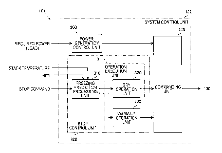
discharged from the fuel cell to the fuel cell, the control method comprising:
a power generation control step of controlling a power generation
state of the fuel cell on the basis of the load; and
a stop control step of stopping the fuel cell system in case of receiving
a stop command of the fuel cell system, wherein
the stop control step comprises:
a freezing prediction step of predicting the freezing of the
component by a detection unit configured to detect a temperature of
the fuel cell system when the stop command of the fuel cell system is
received or after the stop of the fuel cell system; and
an operation execution step of executing a warm-up
operation of the fuel cell system when the freezing of the component
is predicted.
BRIEF DESCRIPTION OF DRAWINGS
[0007] FIG. 1 is a diagram showing the configuration of a fuel cell system
in
an embodiment of the present invention,
FIG. 2 is a block diagram showing a functional configuration of a
controller configured to control the fuel cell system,
FIG. 3 is a flow chart showing an example of a stop method for fuel cell
system,
CA 2955989 2018-10-31
- 2b -
FIG. 4 is a flow chart showing a freezing prevention process,
FIG. 5 is a block diagram showing a configuration for calculating the
amount of ice,
FIG. 6 is a block diagram showing a configuration for controlling a
pressure of cathode gas to be supplied to a fuel cell stack,
FIG. 7 is a block diagram showing a configuration for controlling a flow
CA 2955989 2018-10-31
CA 02955989 2017-01-20
- 3 -
rate of the cathode gas discharged from a compressor,
FIG. 8 is a block diagram showing a configuration for controlling a
pressure of the cathode gas to be supplied to the fuel cell stack,
FIG. 9 is a graph showing a dry request pressure map,
FIG. 10 is a diagram showing a configuration for controlling an output of
a heater for warming cooling water of the fuel cell stack,
FIG. 11 is a block diagram showing a configuration for controlling power
of the fuel cell stack,
FIGS. 12 are time charts when a dry/warm-up operation is executed
during a stop process of the fuel cell system,
FIGS. 13 are time charts showing a controlled state of the cathode gas
during the dry/warm-up operation,
FIGS. 14 are time charts when a dry/warm-up operation is executed after
the stop of a fuel cell system in a third embodiment of the present invention,
and
FIG. 15 is a chart showing a map for correcting a warm-up completion
threshold value of a jet pump.
DESCRIPTION OF EMBODIMENTS
[0008] Hereinafter, embodiments of the present invention are described
with reference to the accompanying drawings.
[0009] (First Embodiment)
FIG. 1 is a diagram showing a configuration example of a fuel cell system
in an embodiment of the present invention.
[0010] A fuel cell system 100 constitutes a power supply system for
supplying fuel gas necessary for power generation from outside to a fuel cell
and causing the fuel cell to generate power according to an electric load. The
fuel cell system 100 is controlled by a controller 101.
CA 02955989 2017-01-20
-4-
100111 The fuel cell system 100 includes a fuel cell stack 1, a battery 2,
a
DC/DC converter 3, electric load 4, a cathode gas supplying/discharging
device 10, an anode gas supplying/discharging device 20, a stack cooling
device 30 and a stack resistance measuring device 45. Each of the cathode
gas supplying/discharging device 10, the anode gas supplying/discharging
device 20 and the stack cooling device 30 is an auxiliary machine used for
causing the fuel cell stack 1 to generate power.
[0012] The battery 2 is a power supply for assisting the fuel cell stack 1.
The battery 2 outputs a voltage of, e.g. several hundreds of V.
[0013] The DC/DC converter 3 is a bidirectional voltage converter for
adjusting a voltage of the fuel cell stack 1 and a voltage of the battery 2
with
respect to each other. The DC/DC converter 3 is connected between the fuel
cell stack 1 and the battery 2. The DC/DC converter 3 is controlled by the
controller 101 and adjusts the voltage of the fuel cell stack 1 using power
output from the battery 2.
[0014] For example, the DC/DC converter 3 reduces the voltage of the fuel
cell stack 1 such that an output current taken out from the fuel cell stack 1
increases as power required from the electric load 4 increases.
[0015] The electric load 4 is driven by power supplied from the fuel cell
stack 1 and the battery 2. Examples of the electric load 4 include an electric
motor for driving a vehicle and some of auxiliary machines of the fuel cell
stack
1.
[0016] In the present embodiment, the electric load 4 is connected to a
power supply line connecting the fuel cell stack 1 and the DC/DC converter 3.
It should be noted that the electric motor may be connected to the power
supply line between the fuel cell stack 1 and the DC/DC converter 3 and some
of the auxiliary machines may be connected to the power supply line between
the battery 2 and the DC/DC converter 3.
CA 02955989 2017-01-20
- 5 -
[0017] The fuel cell stack 1 is such that several hundreds of battery cells
are laminated, and generates a DC voltage of, e.g. several hundreds of V
(volts).
[0018] A fuel cell is composed of an anode electrode (fuel electrode), a
cathode electrode (oxidant electrode) and an electrolyte membrane sandwiched
between the anode electrode and the cathode electrode. In the fuel cell, anode
gas (fuel gas) containing hydrogen in the anode electrode and cathode gas
(oxidant gas) containing oxygen in the cathode electrode induce an
electrochemical reaction (power generation reaction) in the electrolyte
membrane. The following electrochemical reactions proceed in both anode
and cathode electrodes.
[0019] Anode electrode: 2 H2-->4H++4e- ...(1)
Cathode electrode: 4H++4e-+02¨>2H20 ...(2)
[0020] By the above electrochemical reactions (1) and (2), an electromotive
force is generated and, simultaneously, water is generated. Since each of the
fuel cells laminated in the fuel cell stack 1 is connected in series, a total
of cell
voltages generated in the fuel cells becomes an output voltage of the fuel
cell
stack 1.
[0021] The cathode gas is supplied to the fuel cell stack 1 from the
cathode
gas supplying/discharging device 10 and the anode gas is supplied thereto
from the anode gas supplying/discharging device 20.
[0022] The cathode gas supplying/discharging device 10 is a device
configured to supply the cathode gas to the fuel cell stack 1 and discharge
cathode off-gas discharged from the fuel cell stack 1 to atmosphere. The
cathode off-gas contains excess cathode gas not consumed by the fuel cell
stack 1 and impurities such as generated water associated with power
generation.
[0023] The cathode gas supplying/discharging device 10 includes a
cathode gas supply passage 11, a compressor 12, a cathode gas discharge
CA 02955989 2017-01-20
- 6 -
passage 13, a cathode pressure control value 14, a bypass passage 15 and a
bypass valve 16.
[0024] The cathode gas supply passage 11 is a passage for supplying the
cathode gas to the fuel cell stack 1. One end of the cathode gas supply
passage 11 communicates with a passage for taking in air containing oxygen
from outside air and the other end is connected to a cathode gas inlet hole of
the fuel cell stack 1.
[0025] The compressor 12 is provided in the cathode gas supply passage 11.
The compressor 12 takes air into the cathode gas supply passage 11 from
outside air and supplies the air as the cathode gas to the fuel cell stack 1.
The
compressor 12 is controlled by the controller 101.
[0026] The cathode gas discharge passage 13 is a passage for discharging
the cathode off-gas from the fuel cell stack 1. One end of the cathode gas
discharge passage 13 is connected to a cathode gas outlet hole of the fuel
cell
stack 1 and the other end is open.
[0027] The cathode pressure control value 14 is provided in the cathode gas
discharge passage 13. In the present embodiment, an electromagnetic valve
capable of changing a valve opening degree in a stepwise manner is used as the
cathode pressure control valve 14. The cathode pressure control value 14 is
controlled to open and close by the controller 101. By this open/close
control,
a pressure of the cathode gas to be supplied to the fuel cell stack 1 is
adjusted
to a desired pressure.
[0028] The bypass passage 15 is a passage for directly discharging part of
the cathode gas discharged from the compressor 12 to the cathode gas
discharge passage 13 without supplying it to the fuel cell stack 1.
[0029] One end of the bypass passage 15 is connected to a part of the
cathode gas supply passage 11 between the compressor 12 and the fuel cell
stack 1 and the other end is connected to a part of the cathode gas discharge
CA 02955989 2017-01-20
- 7 -
passage 13 upstream of the cathode pressure control value 14. Specifically,
the bypass passage 15 is branched off from the cathode gas supply passage 11
at a position downstream of the compressor 12 and joins the cathode gas
discharge passage 13 at a position upstream of the cathode pressure control
valve 14.
[0030] The bypass valve 16 is provided in the bypass passage 15. In the
present embodiment, an electromagnetic valve capable of changing a valve
opening degree in a stepwise manner is used as the bypass valve 16. The
bypass valve 16 is controlled by the controller 101.
[0031] The bypass valve 16 is opened, for example, when a flow rate of the
cathode gas necessary to dilute hydrogen discharged from the fuel cell stack 1
(hereinafter, referred to as a "hydrogen dilution request flow rate") becomes
larger than a flow rate of the cathode gas necessary for the power generation
of
the fuel cell stack 1.
[0032] Alternatively, the bypass valve 16 is opened when a flow rate of the
cathode gas necessary to avoid a surge occurring in the compressor 12
(hereinafter, referred to as a "surge avoidance request flow rate") becomes
larger than the flow rate of the cathode gas necessary for the power
generation
of the fuel cell stack 1.
[0033] It should be noted that the bypass valve 16 is closed when the flow
rate of the cathode gas necessary for the power generation of the fuel cell
stack
1 is larger than values such as the hydrogen dilution request flow rate and
the
surge avoidance request flow rate.
[0034] The anode gas supplying/discharging device 20 is a device
configured to supply the anode gas to the fuel cell stack 1 and remove
impurities in anode off-gas discharged from the fuel cell stack 1 while
circulating the anode off-gas to the fuel cell stack 1. The impurities mean
nitrogen in air permeating from the cathode electrodes to the anode electrodes
CA 02955989 2017-01-20
- 8 -
via the electrolyte membranes, generated water associated with power
generation and the like.
[0035] The anode gas supplying/discharging device 20 includes a
high-pressure tank 21, an anode gas supply passage 22, a heat exchanger 23,
an anode pressure control value 24, a jet pump 25, an anode gas circulation
passage 26, a gas-liquid separation device 27, a purge passage 28 and a purge
valve 29.
[0036] The high-pressure tank 21 stores the anode gas to be supplied to the
fuel cell stack 1 in a high-pressure state.
[0037] The anode gas supply passage 22 is a passage for supplying the
anode gas stored in the high-pressure tank 21 to the fuel cell stack 1. One
end of the anode gas supply passage 22 is connected to the high-pressure tank
21 and the other end is connected to an anode gas inlet hole of the fuel cell
stack 1.
[0038] The heat exchanger 23 is provided upstream of the anode pressure
control valve 24 in the anode gas supply passage 22. The heat exchanger 23
exchanges heat between cooling water increased in temperature in the fuel cell
stack 1 and the anode gas supplied from the high-pressure tank 21. The
cooling water is refrigerant for cooling the fuel cell stack 1.
[0039] When the fuel cell system 100 is started at a low temperature, the
heat exchanger 23 has a function of warming the anode gas to be supplied to
the anode gas supply passage 22 by the cooling water circulating through the
fuel cell stack 1.
[0040] The anode pressure control value 24 is provided between the heat
exchanger 23 and the jet pump 25 in the anode gas supply passage 22. In the
present embodiment, an electromagnetic valve capable of changing a valve
opening degree in a stepwise manner is used as the anode pressure control
valve 24. The anode pressure control value 24 is controlled to open and close
CA 02955989 2017-01-20
- 9 -
by the controller 101. By this open/close control, a pressure of the anode gas
to be supplied to the fuel cell stack 1 is adjusted.
[0041] A temperature sensor 41 configured to detect a temperature of the
anode gas supplied from the high-pressure tank 21 (hereinafter, referred to as
a "supplied gas temperature") is provided between the anode pressure control
valve 24 and the jet pump 25 in the anode gas supply passage 22. The
temperature sensor 41 outputs a detection signal indicating the detected
temperature to the controller 101.
[0042] It should be noted that although the temperature sensor 41 is
provided between the anode pressure control valve 24 and the jet pump 25 in
the anode gas supply passage 22 in the present embodiment, it may be
provided between the heat exchanger 23 and the anode pressure control valve
24 in the anode gas supply passage 22.
[0043] The jet pump 25 is provided between the anode pressure control
valve 24 and the fuel cell stack 1 in the anode gas supply passage 22. The jet
pump 25 is a pump or ejector for causing the anode gas circulation passage 26
to join the anode gas supply passage 22. By using the jet pump 25, the anode
off-gas can be circulated to the fuel cell stack 1 by a simple configuration.
[0044] The jet pump 25 sucks the anode off-gas discharged from the fuel
cell stack 1 and circulates that anode off-gas to the fuel cell stack 1 by
increasing a flow velocity of the anode gas supplied by the anode pressure
control valve 24.
[0045] The jet pump 25 is composed, for example, of a nozzle and a
diffuser.
The nozzle is for accelerating the flow velocity of the anode gas and
injecting
the anode gas to the diffuser. The nozzle is formed into a hollow cylindrical
shape and an opening is narrowed toward a tip part of the nozzle. Thus, the
flow velocity of the anode gas is increased in the tip part and the anode gas
is
injected into the diffuser.
CA 02955989 2017-01-20
- 10 -
[0046] The diffuser is for sucking the anode off-gas by the flow velocity
of
the anode gas injected from the nozzle. The diffuser causes the anode gas
injected from the nozzle and the sucked anode off-gas to join and discharges
gas after joining to the fuel cell stack 1. The diffuser is formed with a
confluent passage on the same axis as the nozzle. An opening of the
confluent passage is formed to be wider toward a discharge port. The diffuser
is formed with a hollow cylindrical suction chamber extending from a suction
port to the tip part of the nozzle and the suction chamber and the confluent
passage communicate.
[0047] A pressure sensor 42 is provided between the jet pump 25 and the
fuel cell stack 1 in the anode gas supply passage 22. The pressure sensor 42
detects a pressure of the anode gas to be supplied to the fuel cell stack 1
(hereinafter, referred to as a "stack inlet gas pressure"). The pressure
sensor
42 outputs a detection signal indicating the detected pressure to the
controller
101.
[0048] The anode gas circulation passage 26 is a passage for circulating
the
anode off-gas discharged from the fuel cell stack 1 to the anode gas supply
passage 22. One end of the anode gas circulation passage 26 is connected to
an anode gas outlet hole of the fuel cell stack 1 and the other end is
connected
to the suction port (circulation port) of the jet pump 25.
[0049] The liquid-gas separation device 27 is provided in the anode gas
circulation passage 26. The liquid-gas separation device 27 separates
impurities such as generated water and nitrogen gas contained in the anode
off-gas from excess anode gas. The liquid-gas separation device 27 condenses
steam contained in the anode off-gas into liquid water.
[0050] The anode gas having the impurities removed in the liquid-gas
separation device 27 passes in the anode gas circulation passage 26 and is
supplied to the anode gas supply passage 22 again via the jet pump 25.
CA 02955989 2017-01-20
11 -
Further, a discharge hole for discharging the impurities to the purge passage
28 is formed in a lower part of the liquid-gas separation device 27.
[0051] The purge passage 28 is a passage for discharging the impurities
separated by the liquid-gas separation device 27. One end of the purge
passage 28 is connected to the discharge hole of the liquid-gas separation
device 27 and the other end is connected to a part of the cathode gas
discharge
passage 13 downstream of the cathode pressure control valve 14.
[0052] The purge valve 29 is provided in the purge passage 28. The purge
valve 29 is controlled to open and close by the controller 101. By this
open/close control, the impurities such as nitrogen gas and liquid water are
discharged to the cathode gas discharge passage 13.
[0053] The stack cooling device 30 is a device configured to adjust the
fuel
cell stack 1 to a temperature suitable for power generation, using the cooling
water as refrigerant. The stack cooling device 30 includes a cooling water
circulation passage 31, a cooling water pump 32, a radiator 33, a bypass
passage 34, a hater 35, a thermostat 36, a branch passage 37, a stack inlet
water temperature sensor 43 and a stack outlet water temperature sensor 44.
[0054] The cooling water circulation passage 31 is a passage for
circulating
the cooling water to the fuel cell stack 1. One end of the cooling water
circulation passage 31 is connected to a cooling water inlet hole of the fuel
cell
stack 1 and the other end is connected to a cooling water outlet hole of the
fuel
cell stack 1.
[0055] The cooling water pump 32 is provided in the cooling water
circulation passage 31. The cooling water pump 32 supplies the cooling
water to the fuel cell stack 1 and the heat exchanger 23. The cooling water
pump 32 is controlled by the controller 101.
[0056] The radiator 33 is provided on the side of a cooling water suction
port of the cooling water pump 32 in the cooling water circulation passage 31.
CA 02955989 2017-01-20
- 12 -
The radiator 33 cools the cooling water heated by the fuel cell stack 1.
[0057] The bypass passage 34 is a passage bypassing the radiator 33.
One end of the bypass passage 34 is connected to the cooling water circulation
passage 31 on a cooling water outlet side of the fuel cell stack 1, and the
other
end is connected to the thermostat 36.
[0058] The heater 35 is provided in the bypass passage 34. The heater 35
is energized to heat the cooling water when the fuel cell stack 1 is warmed
up.
In the present embodiment, the heater 35 generates heat by having power
supplied from the fuel cell stack 1 by the DC/DC converter 3.
[0059] The thermostat 36 is provided in a part where the bypass passage
34 joins the cooling water circulation passage 31. The thermostat 36 is a
three-way valve. The thermostat 36 automatically opens and closes in
response to the temperature of the cooling water flowing inside the thermostat
36.
[0060] For example, the thermostat 36 is closed and supplies only the
cooling water flowing by way of the bypass passage 34 to the fuel cell stack 1
when the temperature of the cooling water is lower than a predetermined valve
opening temperature. In this way, the cooling water having a higher
temperature than the cooling water flowing by way of the radiator 33 flows
into
the fuel cell stack 1.
[0061] On the other hand, the thermostat 36 starts gradually opening when
the temperature of the cooling water becomes equal to or higher than the valve
opening temperature. Then, the thermostat 36 mixes the cooling water
flowing by way of the bypass passage 34 and the cooling water flowing by way
of the radiator 33 and supplies the mixed cooling water to the fuel cell stack
1.
In this way, the cooling water having a lower temperature than the cooling
water flowing by way of the bypass passage 34 flows into the fuel cell stack
1.
[0062] The branch passage 37 is branched off from the cooling water
CA 02955989 2017-01-20
- 13 -
circulation passage 31 between the cooling water pump 32 and the cooling
water inlet hole of the fuel cell stack 1 and joins the cooling water
circulation
passage 31 at a position upstream of the bypass passage 34 via the heat
exchanger 23.
[0063] The stack inlet water temperature sensor 43 is provided near the
cooling water inlet hole of the fuel cell stack 1 in the cooling water
circulation
passage 31. The stack inlet water temperature sensor 43 detects a
temperature of the cooling water flowing into the fuel cell stack 1
(hereinafter,
referred to as a "stack inlet water temperature"). The stack inlet water
temperature sensor 43 outputs a detection signal indicating the detected
temperature to the controller 101.
[0064] The stack outlet water temperature sensor 44 is provided near the
cooling water outlet hole of the fuel cell stack 1 in the cooling water
circulation
passage 31. The stack outlet water temperature sensor 44 detects a
temperature of the cooling water discharged the fuel cell stack 1
(hereinafter,
referred to as a "stack outlet water temperature"). The stack outlet water
temperature sensor 44 outputs a detection signal indicating the detected
temperature to the controller 101.
[0065] The stack resistance measuring device 45 measures an internal
resistance (HFR: High Frequency Resistance) of the fuel cell stack 1 to
estimate
a degree of wetness of the electrolyte membranes constituting the fuel cells
laminated in the fuel cell stack 1. The smaller the degree of wetness of the
electrolyte membranes, i.e. the less moisture in the electrolyte membranes and
the drier the electrolyte membranes, the larger the internal resistance. On
the other hand, the larger the degree of wetness of the electrolyte membranes,
i.e. the more moisture in the electrolyte membranes and the wetter the
electrolyte membranes, the smaller the internal resistance.
[0066] For example, the stack resistance measuring device 45 supplies an
CA 02955989 2017-01-20
- 14 -
AC current to a positive electrode terminal of the fuel cell stack 1 and
detects
an AC voltage between the positive electrode terminal and a negative electrode
terminal by the AC current. Then, the stack resistance measuring device 45
calculates the internal resistance by dividing an amplitude of the AC voltage
by
an amplitude of the AC current, and outputs a value of the internal
resistance,
i.e. HFR to the controller 101.
[0067] The controller 101 is configured by a microcomputer including a
central processing unit (CPU), a read-only memory (ROM), a random access
memory (RAM) and an input/output interface (I/O interface).
[0068] To the controller 101 are input detection values output from the
temperature sensor 41, the pressure sensor 42, the stack inlet water
temperature sensor 43, the stack outlet water temperature sensor 44 and the
stack resistance measuring device 45.
[0069] The controller 101 controls the compressor 12, the cathode pressure
control valve 14, the bypass valve 16, the anode pressure control valve 24 and
the purge valve 29 on the basis of input values, required power required from
the fuel cell stack 1 and command values to the auxiliary machines. In this
way, a power generation state of the fuel cell stack 1 is satisfactorily
maintained.
[0070] The controller 101 executes a control of warming up the fuel cell
stack 1 to a temperature suitable for power generation (hereinafter, referred
to
as a "warm-up operation") when the fuel cell system 100 is started.
[0071] In the warm-up operation, the controller 101 controls the DC/DC
converter 3 such that power is supplied from the fuel cell stack 1 to the
auxiliary machines such as the compressor 12, the cooling water pump 32 and
the heater 35.
[0072] Since drive power necessary to drive the auxiliary machines is
generated by the fuel cell stack 1, the fuel cell stack 1 itself further
generates
CA 02955989 2017-01-20
- 15 -
heat. In addition, the cooling water in the fuel cell stack 1 is heated to
warm
the fuel cell stack 1 by generated heat (output) of the heater 35.
[0073] At this time, since the amount of heat generation of the fuel cell
stack 1 increases as the amount of power generation of the fuel cell stack 1
increases, the controller 101 sets a rotation speed of the compressor 12 and
an
output of the heater 35 to upper limit values of variable ranges. In this way,
the warm-up of the fuel cell stack 1 is promoted.
[0074] When the fuel cell system as described above is started in a sub-
zero
temperature environment, the temperature of the anode gas supplied from the
high-pressure tank 21 to the jet pump 25 could also reach -30 C.
[0075] In such a situation, steam in the anode off-gas becomes liquid water
and that liquid water is frozen to generate ice in a part where the anode gas
to
be supplied to the jet pump 25 and the anode off-gas to be sucked by the jet
pump 25 join. Thus, the amount of ice formed in the jet pump 25 increases
until the temperature of the joined gas of the anode gas and the anode off-gas
exceeds a freezing point.
[0076] For example, when the fuel cell system 100 is stopped before the
joined gas reaches the freezing point, the formed ice remains in the jet pump
25. If the fuel cell system 100 is restarted in this state, ice is further
generated on the ice formed in the jet pump 25. Thus, a part of a flow passage
where the anode gas and the anode off-gas join may be closed and it may not
be possible to supply the anode gas to the fuel cell stack 1 during the
operation
of the fuel cell system 100. Here, the closure of the flow passage by ice is
referred to as freezing.
[0077] Accordingly, in the present embodiment, the controller 101 executes
the watni-up operation of the fuel cell stack 1 when receiving a stop command
for stopping the power generation of the fuel cell stack 1.
[0078] FIG. 2 is a diagram showing a basic configuration of the controller
CA 02955989 2017-01-20
- 16 -
101 in the first embodiment of the present invention.
[0079] The controller 101 includes a system control unit 102 configured to
control the fuel cell system 100. The system control unit 102 includes a
power generation control unit 200, a stop control unit 300 and a commanding
unit 400.
[0080] The power generation control unit 200 controls the power
generation state of the fuel cell stack 1 on the basis of required power. The
required power is power required to the fuel cell stack 1 from the electric
load 4
such as the electric motor.
[0081] For example, the power generation control unit 200 refers to a
current-voltage (IV) characteristic of the fuel cell stack 1 and calculates a
target value of a current to be taken out from the fuel cell stack 1
(hereinafter,
referred to as a "target current") on the basis of the required power.
[0082] The power generation control unit 200 calculates a target pressure
and a target flow rate of the cathode gas to be supplied to the fuel cell
stack 1
on the basis of the target current thereof and calculates a target pressure of
the anode gas to be supplied to the fuel cell stack 1 on the basis of the
target
current. Further, the power generation control unit 200 calculates a target
flow rate of the cooling water to be supplied to the fuel cell stack 1 on the
basis
of the target current.
[0083] As just described, the power generation control unit 200 obtains the
target pressure and the target flow rate of the cathode gas, the target
pressure
of the anode gas and the target flow rate of the cooling water on the basis of
the
required power of the electric load 4 and causes the fuel cell stack 1 to
generate
power using these parameters.
[0084] The stop control unit 300 controls the fuel cell system 100 to a
stop
state determined in advance on the basis of a stop command of the fuel cell
system 100.
CA 02955989 2017-01-20
- 17 -
[0085] The stop control unit 300 includes a freezing prediction processing
unit 310 and an operation execution unit 311.
[0086] The freezing prediction processing unit 310 constitutes a freezing
prediction unit configured to predict the freezing of the jet pump 25 on the
basis of the temperature of the fuel cell system 100.
[0087] The temperature of the fuel cell system 100 is a parameter for
predicting the freezing of the jet pump 25. For example, an outside air
temperature, the temperature of the fuel cell stack 1, the temperature of the
anode off-gas to be circulated (sucked) to the jet pump 25 (circulating gas
temperature), a supplied gas temperature or the like is used as such.
[0088] The freezing prediction processing unit 310 predicts the freezing of
the jet pump 25 and judges whether or not the fuel cell stack 1 needs to be
controlled to a state determined in advance when receiving a stop command of
the fuel cell system 100.
[0089] The freezing prediction processing unit 310 judges whether or not
the electrolyte membranes of the fuel cell stack 1 need to be controlled to a
dry
state determined in advance. In the present embodiment, the freezing
prediction processing unit 310 judges, on the basis of a value of the internal
resistance (HFR) output from the stack resistance measuring device 45,
whether or not the electrolyte membranes need to be controlled to the dry
state.
[0090] Further, the freezing prediction processing unit 310 judges, on the
basis of the temperature of the fuel cell system 100, whether or not ice
generated in the jet pump 25 needs to be removed.
[0091] In the present embodiment, the freezing prediction processing unit
310 judges, on the basis of the temperature of the fuel cell stack 1
(hereinafter,
referred to as a "stack temperature"), whether or not ice needs to be removed.
For example, the freezing prediction processing unit 310 predicts that the jet
CA 02955989 2017-01-20
- 18 -
pump 25 will be frozen if the stack temperature is lower than a temperature at
which ice in the jet pump 25 is removed.
[0092] In the present embodiment, the freezing prediction processing unit
310 estimates the amount of ice in the jet pump 25 and predicts the freezing
of
the jet pump 25 on the basis of that amount of ice.
[0093] The operation execution unit 311 executes the warm-up operation
without stopping the fuel cell system 100 in the case of receiving the stop
command of the fuel cell system 100 when the freezing of the jet pump 25 is
predicted by the freezing prediction processing unit 310. The operation
execution unit 311 includes a dry operation unit 320 and a warm-up operation
unit 330.
[0094] The dry operation unit 320 executes a dry operation to control the
fuel cell system 100 such that the electrolyte membranes reach a dry state
determined in advance from a wet state if it is judged by the freezing
prediction
processing unit 310 that the electrolyte membranes need to be controlled to
the dry state.
[0095] For example, the dry operation unit 320 increases the target flow
rate of the cathode gas and reduces the target pressure of the cathode gas to
increase a discharge amount of steam carried out from the fuel cell stack 1 by
the cathode gas.
[0096] Further, the dry operation unit 320 warms up the fuel cell stack 1
if
the stack temperature is lower than the freezing point. Since the temperature
of the fuel cell stack 1 increases and the amount of saturated steam in the
fuel
cell stack 1 increases in this way, the discharge amount of steam carried out
by the cathode gas can be increased.
[0097] By executing the dry operation in this way, a situation can be
avoided where the fuel cell stack 1 is cooled by outside air and water
retained
in the electrolyte membranes is frozen to deteriorate the electrolyte
CA 02955989 2017-01-20
- 19 -
membranes after the fuel cell system 100 is stopped.
[0098] On the other hand, the dry operation unit 320 stops the execution of
the dry operation if it is judged by the freezing prediction processing unit
310
that the electrolyte membranes need not be controlled to the dry state. In
this
way, unnecessary execution of the dry operation can be prevented.
[0099] The warm-up operation unit 330 executes the warm-up operation
for warming up the fuel cell stack 1 if it is judged that ice formed in the
jet
pump 25 needs to be removed, i.e. when the freezing of the jet pump 25 is
predicted.
[0100] The warm-up operation unit 330 energizes the heater 35 to heat the
cooling water in the fuel cell stack 1. In addition, the warm-up operation
unit
330 causes the fuel cell stack 1 to generate power, for example, by increasing
the rotation speed of the compressor 12 to increase the power consumption of
the auxiliary machines. In this way, the temperature of the fuel cell stack 1
can be quickly increased.
[0101] Specifically, the warm-up operation unit 330 calculates the target
current on the basis of auxiliary machine power consumption for warming up
the fuel cell stack 1, and calculates the target pressure and the target flow
rate
of the cathode gas and the target pressure of the anode gas on the basis of
that
target current.
[0102] By executing the warm-up operation in this way, the stack
temperature increases and, associated with this, the temperature of the anode
off-gas to be sucked into the jet pump 25 increases, wherefore ice in the jet
pump 25 can be melted.
[0103] On the other hand, the wai _____________________________ ni-up
operation unit 330 stops the
execution of the warm-up operation if it is judged by the freezing prediction
processing unit 310 that ice in the jet pump 25 needs not be removed.
Specifically, the freezing prediction processing unit 310 limits the execution
of
CA 02955989 2017-01-20
- 20 -
the warm-up operation when predicting that the jet pump 25 will not be frozen.
In this way, unnecessary execution of the was ____________________ in-up
operation can be
prevented.
[0104] The commanding unit 400 outputs a command signal to each
control component of the fuel cell system 100 on the basis of the parameter
output from the power generation control unit 200 or the stop control unit
300.
[0105] For
example, the commanding unit 400 calculates a target rotation
speed of the compressor 12 and a target opening degree of the cathode
pressure control valve 14 on the basis of the target pressure and the target
flow
rate of the cathode gas. Further, the commanding unit 400 calculates a
target opening degree of the bypass valve 16 such that the flow rate of the
cathode gas to be supplied to the fuel cell stack 1 reaches the target flow
rate.
Then, the commanding unit 400 outputs command signals indicating
calculation results to the compressor 12, the cathode pressure control valve
14
and the bypass valve 16.
[0106] Further,
the commanding unit 400 calculates an opening degree of
the anode pressure control valve 24 on the basis of the target pressure of the
anode gas and outputs a command signal designating that target opening
degree to the anode pressure control valve 24. Furthermore, the commanding
unit 400 calculates power to be supplied to the heater 35 on the basis of the
target output of the heater 35 and controls the DC/DC converter 3 according
to that target power.
[0107] According
to the first embodiment of the present invention, the fuel
cell system 100 includes the jet pump 25 for circulating the anode off-gas to
the fuel cell stack 1. The controller 101 includes the power generation
control
unit 200 configured to control the power generation state of the fuel cell
stack
1 on the basis of the required power and the freezing prediction processing
unit
CA 02955989 2017-01-20
-21 -
310 configured to predict the freezing of the jet pump 25 on the basis of the
temperature of the fuel cell system 100.
[0108] The operation execution unit 311 warms up the fuel cell stack 1
during or after the stop of the fuel cell system 100 when the freezing is
predicted by the freezing prediction processing unit 310. Examples of a
parameter for predicting the freezing includes the temperature of the fuel
cell
stack 1 correlated with the temperature of the anode off-gas, an estimated
value of the amount of ice in the jet pump 25 and the HFR of the fuel cell
stack
1.
[0109] By warming up the fuel cell stack 1 on the basis of the freezing
prediction of the jet pump 25 in this way after the stop command is received,
ice formed in a flow passage in which the anode gas is circulated can be
reliably removed.
[0110] For example, ice is formed in the jet pump 25 during the warm-up of
the fuel cell stack 1 in such an environment where the fuel cell system 100 is
started at a sub-zero temperature of -30 C, and the fuel cell system 100 could
be stopped in this state. If the fuel cell system 100 is restarted in such a
situation, ice newly generated during the warm-up is further accumulated on
the ice remaining in the jet pump 25, the jet pump 25 is frozen and it may not
be possible to supply the anode gas to the fuel cell stack 1.
[0111] In contrast, since the temperature of the anode off-gas to be sucked
into the jet pump 25 is increased by warming up the fuel cell stack 1 after
the
stop command is received in the present embodiment, the temperature of the
joined gas of the anode gas and the anode off-gas increases to the freezing
point. Since the ice in the jet pump 25 is melted in this way, the closure of
the
flow passage, in which the anode gas is circulated, due to the remaining ice
can be prevented when the fuel cell system 100 is restarted below a freezing
point.
CA 02955989 2017-01-20
- 22 -
[0112] It should be noted that components provided in the flow passage in
which the anode gas is circulated include the pressure sensor 42 and the
gas-liquid separation device 27 besides the jet pump 25. Further, in a fuel
cell system in which a circulation pump is provided in an anode gas
circulation
passage 26, the circulation pump corresponds to such a component. Since
such components are also possibly frozen during the warm-up operation, ice
can be removed from these components by executing the warm-up operation
during a stop process.
[0113] Further, although the fuel cell system 100 of the present
embodiment is for circulating the anode off-gas to the fuel cell stack 1,
effects
and functions similar to those of the present embodiment can be obtained even
if cathode off-gas is circulated to the fuel cell stack 1.
[0114] As described above, in the fuel cell system for circulating at least
one
discharged gas, out of the anode off-gas and the cathode off-gas, to the fuel
cell
stack 1, the warm-up operation is executed according to a frozen state of the
flow passage in which the discharged gas is circulated when the stop
command is issued, whereby the freezing and closure of the flow passage
during the next start can be prevented.
[0115] (Second Embodiment)
FIG. 3 is a flow chart showing a stop method for fuel cell system in a
second embodiment of the present invention.
[0116] A fuel cell system of this embodiment has the same basic
configuration as the fuel cell system 100 shown in FIG. 1. The same
components as those of the fuel cell system 100 are denoted by the same
reference signs and not described in detail below.
[0117] In Step S101, a power generation control unit 200 of a controller
101
controls a power generation state of a fuel cell stack 1 on the basis of
required
power of electric load 4.
CA 02955989 2017-01-20
- 23 -
[0118] In Step
S102, a freezing prediction processing unit 310 of the
controller 101 judges whether or not a stop command for stopping the power
generation of the fuel cell stack 1 has been received. The stop command is
output to a stop control unit 300, for example, when an operation switch
provided in the fuel cell system 100 is set from a start-up state to a stop
state.
[0119] In Step
S103, the freezing prediction processing unit 310 judges
whether or not electrolyte membranes of fuel cells need to be dried if the
stop
command of the fuel cell system 100 has been received.
[0120] In Step
S104, the freezing prediction processing unit 310 sets a dry
flag on if it is judged that the electrolyte membranes need to be dried. In
this
case, an operation execution unit 311 executes a dry operation. In the dry
operation, the operation execution unit 311 increases a flow rate of cathode
gas to be supplied to the fuel cell stack 1 or reduces a pressure of the
cathode
gas so that the electrolyte membranes are dried, and was _________ ills up the
fuel cell
stack 1 when the temperature of the fuel cell stack 1 is low.
[0121] In Step
S105, the freezing prediction processing unit 310 sets a dry
request temperature Td at a was __________________________________ ni-up
completion threshold value Th_e if the
dry flag is set on. The dry request temperature Td is set at a temperature at
which steam contained in the cathode gas increases, e.g. set at 40 C.
[0122] In Step
S106, the freezing prediction processing unit 310 sets the
dry flag off if it is judged that the electrolyte membranes need not be dried.
In
this case, the stop control unit 300 does not execute the dry operation.
[0123] In Step
S107, the freezing prediction processing unit 310 predicts,
on the basis of the amount of ice formed in the jet pump 25, whether or not a
jet pump 25 will be frozen when the fuel cell system 100 is restarted.
[0124] In the
present embodiment, the freezing prediction processing unit
310 judges whether or not the amount of ice in the jet pump 25 is larger than
a freezing prevention threshold value Th_j.
CA 02955989 2017-01-20
- 24 -
[0125] The freezing prevention threshold value Th_j is a threshold value
for
predicting the freezing of the jet pump 25 and determined not to close the jet
pump 25 in consideration of the amount of ice to be newly generated in the jet
pump 25 when the fuel cell system 100 is restarted. The freezing prevention
threshold value Th_j is set at a value of, e.g. about 50 % with respect to the
amount of ice for closing the jet pump 25.
[0126] In Step S108, the freezing prediction processing unit 310 sets a
warm-up flag on if the amount of ice in the jet pump 25 is larger than the
freezing prevention threshold value Th_j. In this case, the operation
execution unit 311 executes the warm-up operation for warming up the fuel
cell stack 1.
[0127] In Step S109, the freezing prediction processing unit 310 sets a
thaw request temperature Tw at the warm-up completion threshold value Th_e
if the warm-up flat has been set on. The thaw request temperature Tw is set
at a temperature at which the ice of the jet pump 25 is removed and, in the
present embodiment, set at 60 C.
[0128] In Step S110, the freezing prediction processing unit 310 sets the
warm-up flag off if the amount of ice in the jet pump 25 is not larger than
the
freezing prevention threshold value Th_j. In this case, the freezing
prediction
processing unit 310 predicts that the jet pump 25 will not be frozen during
the
warm-up operation during the next start and does not execute the warm-up
operation.
[0129] In Step S120, the operation execution unit 311 performs a freezing
prevention process of the fuel cell system 100 according to set states of the
dry
flag and the warm-up flag.
[0130] In Step S111, the stop control unit 300 sets a breaker (not shown)
connected between the fuel cell stack 1 and the electric load 4 to a shut-off
state and stops the fuel cell system 100 after the freezing prevention process
is
CA 02955989 2017-01-20
- 25 -
completed.
[0131] FIG. 4 is a
flow chart showing an example of a process procedure of
the freezing prevention process performed in Step S120 of FIG. 3.
[0132] In Step
S121, the operation execution unit 311 judges whether or
not the warm-up flag has been set off.
[0133] In Step
S122, the operation execution unit 311 judges whether or
not the dry flag has been set off if the warm-up flag has been set off. The
operation execution unit 311 proceeds to a processing of Step S123 without
executing either the warm-up operation or the dry operation if the warm-up
flag and the dry flag have been both set off.
[0134] In Step
S123, the operation execution unit 311 performs a stop
process of the fuel cell system 100. For example, the operation execution unit
311 reduces a voltage of the fuel cell stack 1 to a predetermined value to
suppress the deterioration of the electrolyte membranes due to high potential
and, thereafter, performs a process of stopping the supply of the anode gas
and
the cathode gas to the fuel cell stack 1.
[0135] In Step
S124, the operation execution unit 311 judges whether or
not the dry flag has been set off if the warm-up flag has been set on in Step
S121.
[0136] In Step
S125, the operation execution unit 311 executes the
warm-up operation if the warm-up flag has been set on and the dry flag has
been set off.
[0137] In Step
S126, the operation execution unit 311 judges whether or
not the warm-up operation has been completed. For example, the operation
execution unit 311 judges that the wai ___________________________ ni-up
operation has been completed
and proceeds to the processing of Step S123 if a stack temperature has
become higher than the warm-up completion threshold value The. It should
be noted that the warm-up completion threshold value Th_e is set at the
CA 02955989 2017-01-20
- 26 -
temperature Tw at which the ice of the jet pump 25 melts.
[0138] The temperature of the cooling water circulating through the fuel
cell stack 1 is used as the stack temperature. In the present embodiment, an
average value of a stack inlet water temperature and a stack outlet water
temperature of the cooling water is used as the stack temperature. It should
be noted that the stack inlet water temperature or the stack outlet water
temperature may be used as the stack temperature. Alternatively, a
temperature sensor may be directly provided for the fuel cell stack 1 and a
detection signal output from the temperature sensor may be used.
[0139] In Step S127, the operation execution unit 311 executes both the
warm-up operation and the dry operation if it is judged in Step S124 that the
dry flag has been set on, i.e. if the warm-up flag and the dry flag have been
both set on.
[0140] In Step S128, the operation execution unit 311 judges whether or
not the warm-up operation has been completed. For example, the operation
execution unit 311 judges that the warm-up operation has not been completed
and proceeds to a processing of Step S129 if the stack temperature is lower
than the warm-up completion threshold value Th_e.
[0141] The warm-up completion threshold value Th_e is set at the thaw
request temperature Tw if the warm-up flag has been set on while being set at
the dry request temperature Td lower than the thaw request temperature Tw if
the dry flag is set on with the warm-up flag set off.
[0142] In Step S129, the freezing prediction processing unit 310 judges
whether or not the dry operation has been completed. In the present
embodiment, when the freezing prediction processing unit 310 judges that the
dry operation has been completed, the operation execution unit 311 executes
only the warm-up operation in Step S125 if HFR measured by a stack
resistance measuring device 45 is not smaller than a reference value
CA 02955989 2017-01-20
- 27 -
determined in advance, i.e. if the electrolyte membranes are drier than in a
predetermined dry state.
[0143] On the other hand, the operation execution unit 311 returns to a
processing of Step S127 and executes both the warm-up operation and the dry
operation if the HFR is smaller than the reference value determined in
advance,
i.e. if the electrolyte membranes are wetter than in the predetermined dry
state.
[0144] In Step S130, the operation execution unit 311 judges whether or
not the stack temperature is lower than the dry request temperature Td set at
the warm-up completion threshold value Th_e if it is judged in Step S122 that
the dry flag has been set on.
[0145] An advance is made to the processing of Step S127 if the stack
temperature is lower than the dry request temperature Td, whereas an
advance is made to a processing of Step 131 if the stack temperature is not
lower than the dry request temperature Td.
[0146] In Step S131, the operation execution unit 311 executes only the dry
operation if it is judged in Step S128 that the warm-up operation has been
completed or if it is judged in Step S130 that the stack temperature is not
lower than the dry request temperature Td.
[0147] In Step S132, the freezing prediction processing unit 310 judges
whether or not the dry operation has been completed. For example, when the
freezing prediction processing unit 310 judges that the dry operation has not
been completed, the operation execution unit 311 returns to the processing of
Step S131 to continue the dry operation if the HFR is lower than a reference
value, i.e. if the electrolyte membranes are wetter than in the predetermined
dry state.
[0148] The operation execution unit 311 performs the stop process in Step
S123, finishes the freezing prevention process and returns to the stop method
CA 02955989 2017-01-20
- 28 -
for the fuel cell system 100 shown in FIG. 3 if it is judged that the dry
operation
has been completed.
[0149] Next, a technique for estimating the amount of ice to be generated
in
the jet pump 25 is described.
[0150] FIG. 5 is a block diagram showing a part of the configuration of the
freezing prediction processing unit 310 in the present embodiment. The
freezing prediction processing unit 310 is provided with an ice amount
calculation unit 340 configured to calculate the amount of ice in the jet pump
25.
[0151] The ice amount calculation unit 340 includes a supplied gas flow
rate calculation unit 341, a circulating gas flow rate calculation unit 342, a
pre-joining supplied gas enthalpy calculation unit 343 and a circulating gas
enthalpy calculation unit 344. Further, the ice amount calculation unit 340
includes a circulating gas volume ratio calculation unit 345, a post-joining
gas
temperature calculation unit 346 and an ice amount integration unit 347.
[0152] The supplied gas flow rate calculation unit 341 calculates a flow
rate
of the anode gas to be supplied to the fuel cell stack 1 (hereinafter,
referred to
as a "supplied gas flow rate") on the basis of a target current of the fuel
cell
stack 1.
[0153] The target current is calculated on the basis of power required from
load such as an electric motor and auxiliary machines. For example, the
target current increases as a depressed amount of an accelerator pedal
increases since power required from the electric motor increases.
[0154] The circulating gas flow rate calculation unit 342 calculates a flow
rate of the anode off-gas circulated from the fuel cell stack 1 to the jet
pump 25
(hereinafter, referred to as a "circulating gas flow rate") on the basis of
the
target current of the fuel cell stack 1 and a purge flow rate. It should be
noted
that the purge flow rate is calculated on the basis of the target current of
the
CA 02955989 2017-01-20
- 29 -
fuel cell stack 1 and an opening degree of a purge valve 29.
[0155] The pre-joining supplied gas enthalpy calculation unit 343
calculates an enthalpy of pre-joining supplied gas on the basis of a flow rate
of
the anode gas supplied from a high-pressure tank 21 to the jet pump 25
(hereinafter, referred to as a "pre-joining supplied gas flow rate") and a
supplied gas temperature. The pre-joining supplied gas flow rate is a value
obtained by subtracting a hydrogen gas flow rate in the circulating gas from
the supplied gas flow rate. The supplied gas temperature is the temperature
of the anode gas to be supplied to the jet pump 25 and calculated on the basis
of a detection signal output from the temperature sensor 41.
[0156] The circulating gas enthalpy calculation unit 344 calculates an
enthalpy of the anode off-gas (circulating gas) to be circulated to the jet
pump
25 on the basis of the circulating gas flow rate and the stack temperature.
Here, the stack temperature is used as the temperature of the anode off-gas to
be sucked into the jet pump 25 (stack outlet gas temperature).
[0157] The circulating gas volume ratio calculation unit 345 calculates a
volume ratio of hydrogen gas, nitrogen gas and stream in the circulating gas.
[0158] Specifically, the circulating gas volume ratio calculation unit 345
calculates a volume ratio of hydrogen gas in the circulating gas from a map
determined in advance on the basis of the target current of the fuel cell
stack 1.
Further, the circulating gas volume ratio calculation unit 345 calculates a
stack outlet gas pressure by subtracting a pressure loss in the fuel cell
stack 1
from a stack inlet gas pressure, and calculates a steam volume ratio by
dividing the stack outlet gas pressure by a saturated stream pressure obtained
from the stack temperature. Then, the circulating gas volume ratio
calculation unit 345 calculates a nitrogen gas volume ratio from the volume
ratios of the hydrogen gas and the steam in the circulating gas.
[0159] The post-joining gas temperature calculation unit 346 calculates the
CA 02955989 2017-01-20
- 30 -
temperature of post-joining gas obtained by joining the pre-joining supplied
gas and the circulating gas in the jet pump 25.
[0160] Specifically, the post-joining gas temperature calculation unit 346
calculates a total enthalpy of the pre-joining gas by adding the enthalpies of
the pre-joining supplied gas and the circulating gas.
[0161] Subsequently, the post-joining gas temperature calculation unit
346 integrates a heat capacity obtained by multiplying specific heat of the
hydrogen gas by the supplied gas flow rate, a heat capacity obtained by
multiplying a nitrogen gas flow rate in the circulating gas by specific heat
of the
nitrogen gas and a heat capacity obtained by multiplying a steam flow rate in
the circulating gas by steam specific heat on the basis of the volume ratio of
the circulating gas. The post-joining gas temperature calculation unit 346
calculates the gas temperature after joining by dividing the total enthalpy
before joining by the integrated heat capacity.
[0162] The ice amount integration unit 347 integrates an ice amount V in
the jet pump 25 as in the following equation, using a pre-joining supplied gas
flow rate Qo, a steam flow rate Qo_H2o in the pre-joining supplied gas, a
circulating gas flow rate Q 1, a steam flow rate Q1_1120 in the circulating
gas, a
saturated steam pressure P
2_sat after joining and a pressure P2 after joining.
[0163] [Equation 1]
P2 sal
= (Q1 H20 Q0 H20) ¨0 = (Vt V1 H20 + Q0 Q0 _H20) ' = = (3)
=2 A2 sat
[0164] It should be noted that the steam flow rate Q1 J-120 in the
circulating
gas is calculated on the basis of the circulating gas flow rate Qi and the
steam
volume ratio calculated by the circulating gas volume ratio calculation unit
345. The saturated steam pressure P2_sat after joining is calculated on the
basis of the post-joining gas temperature calculated by the post-joining gas
CA 02955989 2017-01-20
- 31 -
temperature calculation unit 346. The pressure P2 after joining is the stack
inlet pressure detected by the pressure sensor 42. Further, in the present
embodiment, the steam flow rate QO_H2() in the supplied gas is set at zero
since
it is negligibly small.
[0165] In this way, the ice amount calculation unit 340 calculates the
amount of ice in the jet pump 25 using parameters such as the target current,
the supplied gas temperature, the stack temperature and the stack inlet
pressure as parameters for predicting the freezing.
[0166] Next, a detailed configuration of a system control unit 102 in the
present embodiment is described with reference to each of FIGS. 6 to 11. The
system control unit 102 includes a stack flow rate control unit 500, a
compressor flow rate control unit 600, a stack pressure control unit 700, a
heater output control unit 800 and a stack power control unit 900.
[0167] FIG. 6 is a block diagram showing an example of a detailed
configuration of the stack flow rate control unit 500.
[0168] The stack flow rate control unit 500 controls a flow rate of the
cathode gas to be supplied to the fuel cell stack 1 (hereinafter, referred to
as a
"stack flow rate").
[0169] The stack flow rate control unit 500 includes a power generation
request flow rate calculation unit 200A, a wetness adjusting flow rate
calculation unit 200B, a switcher 310A, a dry request flow rate holding unit
320A and a stack target flow rate setting unit 510.
[0170] The power generation request flow rate calculation unit 200A
calculates a stack flow rate necessary for the power generation of the fuel
cell
stack 1 (hereinafter, referred to as a "power generation request flow rate")
on
the basis of the target current of the fuel cell stack 1. It should be noted
that
the power generation request flow rate calculation unit 200A constitutes the
power generation control unit 200 shown in FIG. 2.
CA 02955989 2017-01-20
- 32 -
[0171] The power generation request flow rate calculation unit 200A
increases the power generation request flow rate to increase the amount of
power generation of the fuel cell stack 1 as the target current of the fuel
cell
stack 1 increases.
[0172] For example, a power generation request map indicating a
relationship between the target current of the fuel cell stack 1 and the power
generation request flow rate of the cathode gas is stored in advance in the
power generation request flow rate calculation unit 200A. When obtaining
the target current, the power generation request flow rate calculation unit
200A refers to the power generation request map and outputs the power
generation request flow rate associated with that target current to the stack
target flow rate setting unit 510.
[0173] The wetness adjusting flow rate calculation unit 200B calculates
such a stack flow rate that a wet/dry state of the electrolyte membranes
reaches a targeted state (hereinafter, referred to as a "wetness adjusting
flow
rate") on the basis of the HFR (internal resistance) and the target current of
the
fuel cell stack 1. It should be noted that the wetness adjusting flow rate
calculation unit 2003 constitutes the power generation control unit 200
shown in FIG. 2.
[01741 The wetness adjusting flow rate calculation unit 200B calculates the
wetness adjusting flow rate according to a difference (deviation) between the
HFR and a reference value determined in advance. For example, the wetness
adjusting flow rate calculation unit 200B increases the wetness adjusting flow
rate to increase the flow rate of steam carried out by the cathode gas if the
HFR
is smaller than the reference value, i.e. if the electrolyte membranes are
wetter
than in the targeted state.
[0175] The reference value of the HFR is set to reduce a water retention
capacity of the electrolyte membranes within such a range that the electrolyte
CA 02955989 2017-01-20
- 33 -
membranes are not deteriorated. Specifically, the reference value is set such
that the electrolyte membranes are drier than in a wet/dry state suitable for
power generation. This can prevent water retained in the electrolyte
membranes from being frozen to freeze the electrolyte membranes after the
stop of the fuel cell system 100.
[0176] Further, the wetness adjusting flow rate calculation unit 200B
increases the wetness adjusting flow rate as the target current of the fuel
cell
stack 1 increases since the amount of steam generated by power generation
increases and the electrolyte membranes are likely to become wetter. On the
other hand, the wetness adjusting flow rate calculation unit 200B reduces the
wetness adjusting flow rate as the target current decreases since the amount
of generated steam is reduced.
[0177] For example, a wetness adjustment map indicating a relationship
between the HFR and the wetness adjusting flow rate is stored for each target
current determined in advance in the wetness adjusting flow rate calculation
unit 200B. When receiving the target current and the HFR, the wetness
adjusting flow rate calculation unit 200B refers to the wetness adjustment
map specified by that target current and calculates the wetness adjusting flow
rate associated with that HFR. The wetness adjusting flow rate calculation
unit 200B outputs that calculated wetness adjusting flow rate to the stack
target flow rate setting unit 510.
[0178] The dry request flow rate holding unit 320A holds a stack flow rate
determined to dry the electrolyte membranes (hereinafter, referred to as a
"dry
request flow rate") after receiving a stop command. Specifically, the dry
request flow rate holding unit 320A outputs the dry request flow rate to
execute the dry operation. It should be noted that the dry request flow rate
holding unit 320A constituting the dry operation unit 320 shown in FIG. 2.
[0179] The dry request flow rate is set at a value larger than the wetness
CA 02955989 2017-01-20
- 34 -
adjusting flow rate to increase a discharge amount of steam carried out by the
cathode gas. It should be noted that the dry request flow rate is not limited
to
a fixed value and may be changed, for example, according to a temperature
state of the fuel cell stack 1.
[0180] The switcher 310A switches a value to be output to the stack target
flow rate setting unit 510 to the wetness adjusting flow rate or the dry
request
flow rate according to a set state of the dry flag. It should be noted that
the
switcher 310A constitutes the freezing prediction processing unit 310 shown
in FIG. 2.
[0181] The switcher 310A outputs the dry request flow rate to the stack
target flow rate setting unit 510 if the dry flag has been set on, i.e. if the
dry
operation is executed during the stop of the fuel cell system 100. On the
other
hand, the switcher 310A outputs the wetness adjusting flow rate to the stack
target flow rate setting unit 510 if the dry flag has been set off, i.e. if
the dry
operation is not executed.
[0182] The stack target flow rate setting unit 510 outputs the larger one
of
the value output from the power generation request flow rate calculation unit
200A and the value output from the switcher 310A as a stack target flow rate
to the commanding unit 400.
[0183] As just described, a switch is made from the wetness adjusting flow
rate to the dry request flow rate to increase the flow rate of the cathode gas
if
the dry flag has been set on during the stop of the fuel cell system 100.
Since
the flow rate of steam carried out from the fuel cell stack 1 by the cathode
gas
increases in this way, the electrolyte membranes of the fuel cell stack 1 can
be
quickly dried.
[0184] FIG. 7 is a block diagram showing an example of a detailed
configuration of the compressor flow rate control unit 600.
[0185] The compressor flow rate control unit 600 controls a flow rate of
the
CA 02955989 2017-01-20
- 35 -
cathode gas discharged from the compressor 12 (hereinafter, referred to as a
"compressor flow rate").
[0186] The compressor flow rate control unit 600 includes a power
generation request flow rate calculation unit 200A, a warm-up release
information holding unit 310B, a switcher 310C, a warm-up request flow rate
holding unit 330A and a stack request flow rate setting unit 610. Further, the
compressor flow rate control unit 600 includes an excessive drying prevention
request flow rate calculation unit 620, a stack flow rate limiting unit 630, a
hydrogen dilution request flow rate calculation unit 640 and a compressor
target flow rate setting unit 650.
[0187] The power generation request flow rate calculation unit 200A is not
described here since having the same configuration as the power generation
request flow rate calculation unit 200A shown in FIG. 6.
[0188] The warm-up request flow rate holding unit 330A holds a
compressor flow rate determined to warm up the fuel cell stack 1 (hereinafter,
referred to as a "warm-up request flow rate") after receiving a stop command
of
the fuel cell system 100. Specifically, the warm-up request flow rate holding
unit 330A outputs the warm-up request flow rate to execute the warm-up
operation. It should be noted that the warm-up request flow rate holding unit
330A constitutes the warm-up operation unit 330 shown in FIG. 2.
[0189] The warm-up request flow rate is set at a value larger than the
power
generation request flow rate to increase power consumed by the compressor 12.
For example, the warm-up request flow rate is set at an upper limit value of
the
rotation speed of the compressor 12, i.e. a maximum value of the flow rate of
the cathode gas dischargeable by the compressor 12. It should be noted that
the warm-up request flow rate is not limited to a fixed value and may be
changed, for example, according to the temperature state of the fuel cell
stack
1.
CA 02955989 2017-01-20
- 36 -
[0190] The warm-up release information holding unit 310B holds zero as a
value for releasing the warm-up operation.
[0191] The switcher 3100 switches a value to be output to the stack
request flow rate setting unit 610 to the warm-up request flow rate or zero
according to the set state of the warm-up flag. It should be noted that the
switcher 310C constitutes the freezing prediction processing unit 310 shown
in FIG. 2.
[0192] The switcher 3100 outputs the warm-up request flow rate to the
stack request flow rate setting unit 610 if the warm-up flag has been set on,
i.e.
if the warm-up operation is executed during the stop of the fuel cell system
100.
On the other hand, the switcher 3100 outputs zero as the value for releasing
the warm-up operation to the stack request flow rate setting unit 610 if the
warm-up flag has been set off, i.e. if the warm-up operation is not executed.
[0193] The stack request flow rate setting unit 610 outputs the larger one
of
the value output from the power generation request flow rate calculation unit
220A and the value output from the switcher 310C as the stack request flow
rate.
[0194] For example, the stack request flow rate setting unit 610 outputs
the warm-up request flow rate larger than the power generation request flow
rate to the stack flow rate limiting unit 630 if the warm-up flag is set on
when
the fuel cell system 100 is stopped.
[0195] The excessive drying prevention request flow rate calculation unit
620 calculates a compressor flow rate for preventing the electrolyte
membranes from becoming excessively dry (hereinafter, referred to as an
"excessive drying prevention flow rate") on the basis of the HFR measured by
the stack resistance measuring device 45.
[0196] The excessive drying prevention request flow rate calculation unit
620 reduces the excessive drying prevention request flow rate to reduce the
CA 02955989 2017-01-20
- 37 -
flow rate of steam carried out from the fuel cell stack 1 by the cathode gas
as
the HFR increases.
[0197] An excessive drying prevention map indicating a relationship
between the HFR and the excessive drying prevention request flow rate is
stored in advance in the excessive drying prevention request flow rate
calculation unit 620. The excessive drying prevention map is generated in
advance on the basis of experimental data and the like. The excessive drying
prevention request flow rate calculation unit 620 outputs a calculation result
to the stack flow rate limiting unit 630.
[0198] The stack flow rate limiting unit 630 outputs the smaller one of the
stack request flow rate and the excessive drying prevention request flow rate
as
the stack flow rate. For example, if the excessive drying prevention request
flow rate is smaller than the stack request flow rate, the stack flow rate
limiting
unit 630 outputs the excessive drying prevention request flow rate to the
compressor target flow rate setting unit 650.
[0199] The hydrogen dilution request flow rate calculation unit 640
calculates a compressor flow rate for reducing a hydrogen concentration in the
anode gas diluted by the cathode gas to or below a specified value
(hereinafter,
referred to as a "hydrogen dilution request flow rate") on the basis of the
purge
flow rate.
[0200] The purge flow rate is a discharge amount of the anode off-gas
purged from the purge valve 29. For example, the purge flow rate is
calculated on the basis of an opening degree of the purge valve 29.
[0201] For example, the hydrogen dilution request flow rate calculation
unit 640 increases the hydrogen dilution request flow rate as the purge flow
rate increases so that the hydrogen concentration does not exceed the
specified value. The hydrogen dilution request flow rate calculation unit 640
outputs that calculation result to the compressor target flow rate setting
unit
CA 02955989 2017-01-20
- 38 -
650.
[0202] The compressor target flow rate setting unit 650 outputs the larger
one of the stack flow rate and the hydrogen dilution request flow rate as the
compressor target flow rate. For example, if the hydrogen dilution request
flow rate is larger than the stack flow rate, the compressor target flow rate
setting unit 650 outputs the hydrogen dilution request flow rate to the
commanding unit 400.
[0203] As just described, the warm-up request flow rate is set at the
compressor target flow rate when the warm-up request flow rate is smaller
than the excessive drying prevention request flow rate and larger than the
hydrogen dilution request flow rate if the warm-up flag has been set on. Since
the cathode gas is supplied from the compressor 12 to the fuel cell stack 1
and
the anode gas is supplied to the fuel cell stack 1 by the anode pressure
control
valve 24 during the stop of the fuel cell stack 1 in this way, the fuel cell
stack 1
can be caused to generate power to be warmed up.
[0204] FIG. 8 is a block diagram showing an example of a detailed
configuration of the stack pressure control unit 700.
[0205] The stack pressure control unit 700 controls a pressure of the
cathode gas to be supplied to the fuel cell stack 1 (hereinafter, referred to
as a
"stack pressure").
[0206] The stack pressure control unit 700 includes a power generation
request pressure calculation unit 200C, a wetness adjusting pressure
calculation unit 200D, a switcher 310D, a warm-up release information
holding unit 310B, a switcher 310E, a dry request pressure calculation unit
320B and a warm-up request pressure holding unit 330B. Further, the stack
pressure control unit 700 includes a stack target pressure setting unit 710.
[0207] The power generation request pressure calculation unit 200C
calculates a stack pressure necessary for the power generation of the fuel
cell
CA 02955989 2017-01-20
- 39 -
stack 1 (hereinafter, referred to as a "power generation request pressure") on
the basis of the target current of the fuel cell stack 1. It should be noted
that
the power generation request pressure calculation unit 200C constitutes the
power generation request control unit 200 shown in FIG. 2.
[0208] The power generation request pressure calculation unit 200C
increases the power generation request pressure as the target current
increases so that the amount of power generation of the fuel cell stack 1
increases. For example, a power generation request pressure map indicating
a relationship between the target current and the power generation request
pressure is stored in advance in the power generation request pressure
calculation unit 200C. The power generation request pressure map is set on
the basis of experimental data and the like.
[0209] Further, the power generation request pressure calculation unit
200C may correct the power generation request pressure according to a partial
pressure change of impurity gas such as steam and nitrogen in the cathode
gas. For example, the power generation request pressure calculation unit
200C increases the power generation request pressure as an atmospheric
pressure or the stack temperature increases. The power generation request
pressure calculation unit 200C outputs that calculation result to the stack
pressure setting unit 710.
[0210] The wetness adjusting pressure calculation unit 200D calculates
such a stack pressure that a wet/dry state of the electrolyte membranes
reaches a targeted state (hereinafter, referred to as a "wetness adjusting
pressure") on the basis of the HFR and the target current of the fuel cell
stack
1. It should be noted that the wetness adjusting pressure calculation unit
200D constitutes the power generation request control unit 200 shown in FIG.
2.
[0211] The wetness adjusting pressure calculation unit 200D calculates
CA 02955989 2017-01-20
- 40 -
the wetness adjusting pressure according to a difference between the HFR and
the reference value determined in advance. For example, the wetness
adjusting pressure calculation unit 200D reduces the wetness adjusting
pressure to increase the discharge amount of steam carried out by the cathode
gas if the HFR is smaller than the reference value, i.e. if the electrolyte
membranes are wetter than in a targeted wet state.
[0212] The reference value of the HFR described above is set to reduce a
water retention capacity of the electrolyte membranes within such a range that
the electrolyte membranes are not deteriorated. Specifically, the reference
value is set such that the electrolyte membranes are drier than in a wet/dry
state suitable for power generation. This can prevent water retained in the
electrolyte membranes from being frozen to freeze the electrolyte membranes
after the stop of the fuel cell system 100.
[0213] Further, the wetness adjusting pressure calculation unit 200D
reduces the wetness adjusting pressure as the target current increases since
the amount of steam generated by power generation increases, and increases
the wetness adjusting pressure as the target current decreases since the
amount of generated steam decreases.
[0214] A wetness adjusting pressure map indicating a relationship between
the HFR and the wetness adjusting pressure is stored for each target current
determined in advance in the wetness adjusting pressure calculation unit
200D. When receiving the target current and the HFR, the wetness adjusting
pressure calculation unit 200D refers to the wetness adjusting pressure map
specified by that target current and calculates the wetness adjusting pressure
associated with that HFR. The wetness adjusting pressure calculation unit
200D outputs that calculated wetness adjusting pressure to the stack target
pressure setting unit 710.
[0215] The dry request pressure calculation unit 320B calculates a
CA 02955989 2017-01-20
- 41 -
pressure of the cathode gas to be supplied to the fuel cell stack 1 to set the
electrolyte membranes in a predetermined dry state (hereinafter, referred to
as
a "dry request pressure") on the basis of the HFR of the fuel cell stack 1.
Specifically, the dry request pressure calculation unit 320B outputs the dry
request pressure to execute the dry operation. It should be noted that the dry
request pressure calculation unit 320B constitutes the dry operation unit 320
shown in FIG. 2.
[0216] The dry request pressure calculation unit 320B increases the dry
request pressure to reduce the discharge amount of steam carried out by the
cathode gas as the HFR increases, i.e. as the electrolyte membranes approach
the predetermined dry state.
[0217] In the present embodiment, a dry request pressure map indicating a
relationship between the HFR and the dry request pressure is stored in
advance in the dry request pressure calculation unit 320B. The dry request
pressure map is described later with reference to FIG. 9.
[0218] The switcher 310D switches a value to be output to the stack target
pressure setting unit 710 to the wetness adjusting pressure or the dry request
pressure according to the set state of the dry flag. It should be noted that
the
switcher 310D constitutes the freezing prediction processing unit 310 shown
in FIG. 2.
[0219] The switcher 310D outputs the dry request pressure to the stack
target pressure setting unit 710 if the dry flag has been set on, i.e. if the
dry
operation is executed during the stop of the fuel cell system 100. On the
other
hand, the switcher 310D outputs the wetness adjusting pressure to the stack
target pressure setting unit 710 if the dry flag has been set off, i.e. the
dry
operation is not executed.
[0220] The warm-up request pressure holding unit 330B holds a pressure
of the cathode gas necessary for the warm-up of the fuel cell stack 1
CA 02955989 2017-01-20
- 42 -
(hereinafter, referred to as a "warm-up request pressure") to melt ice formed
in
the jet pump 25 after receiving a stop command of the fuel cell system 100.
Specifically, the warm-up request pressure holding unit 330B outputs the
warm-up request pressure to execute the warm-up operation. It should be
noted that the warm-up request pressure holding unit 330B constitutes the
warm-up operation unit 330 shown in FIG. 2.
[0221] The warm-up request pressure is set to increase the power
consumption of the compressor 12 and set at a value larger than the dry
request pressure. It should be noted that the wanii-up request pressure is
not limited to a fixed value and may be set at a smaller value, for example,
as
the temperature of the fuel cell stack 1 increases.
[0222] The warm-up release information holding unit 310B holds zero as a
value for releasing the warm-up operation.
[0223] The switcher 310E switches a value to be output to the stack target
pressure setting unit 710 to the warm-up request pressure or zero according to
the set state of the warm-up flag. It should be noted that the switcher 310E
constitutes the freezing prediction processing unit 310 shown in FIG. 2.
[0224] The switcher 310E outputs the warm-up request pressure to the
stack target pressure setting unit 710 if the warm-up flag has been set on,
i.e.
if the walla-up operation is executed during the stop of the fuel cell system
100.
On the other hand, the switcher 310E outputs zero as the value for releasing
the warm-up operation to the stack target pressure setting unit 710 if the
warm-up flag has been set off, i.e. if the warm-up operation is not executed.
[0225] The stack target pressure setting unit 710 outputs the largest one
of
the power generation request pressure, the wetness adjusting pressure or the
dry request pressure output from the switcher 310E and the warm-up request
pressure or zero output from the switcher 310E as a stack target pressure to
the commanding unit 400.
CA 02955989 2017-01-20
- 43 -
[0226] The stack
target pressure setting unit 710 outputs the warm-up
request pressure larger than the dry request pressure to the commanding unit
400, for example, if the dry flag and the warm-up flag are both set on when a
stop command is received.
Specifically, the warm-up operation is
preferentially executed.
[0227] The reason
for this is that the discharge amount of steam carried
out by the cathode gas does not increase very much even if the pressure of the
cathode gas is reduced since the amount of saturated steam in the fuel cell
stack 1 is very small when the temperature of the fuel cell stack 1 is lower
than
0 C.
[0228] By
increasing the pressure of the cathode gas on the contrary, the
power consumption of the compressor 12 increases and the amount of power
generation of the fuel cell stack 1 increases, wherefore a temperature
increase
of the fuel cell stack 1 can be promoted. Since the amount of saturated steam
in the fuel cell stack 1 increases in this way, the discharge amount of steam
can be increased and the fuel cells can be dried early as compared to the case
where the pressure of the cathode gas is reduced.
[0229] FIG. 9 is a
graph showing the dry request pressure map set in the
dry request pressure calculation unit 320B. Here, a horizontal axis
represents the HFR of the fuel cell stack 1 and a vertical axis represents the
dry request pressure.
[0230] The dry
request pressure map is set to reduce the dry request
pressure as the HFR decreases, i.e. as the electrolyte membranes of the fuel
cells become wetter. In this way, the discharge amount of steam carried out
from the fuel cell stack 1 by the cathode gas increases as the HFR decreases.
Further, the dry request pressure is set at a value smaller than the warm-up
request pressure.
[0231] FIG. 10 is
a block diagram showing an example of a detailed
CA 02955989 2017-01-20
- 44 -
configuration of the heater output control unit 800.
[0232] The heater
output control unit 800 controls the amount of generated
heat output from the heater 35 (hereinafter, referred to as a "heater
output").
[0233] The heater
output control unit 800 includes a warm-up release
information holding unit 310B, a switcher 310F, a warm-up request output
holding unit 330C, a component protection request output calculation unit
810 and a heater output limiting unit 820.
[0234] The warm-up
request output holding unit 330C holds a heater
output determined to warm up the fuel cell stack 1 (hereinafter, referred to
as
a "warm-up request output") after receiving a stop command of the fuel cell
system 100. Specifically, the wal ________________________________ in-up
request output holding unit 330C
outputs the warm-up request output to execute the warm-up operation. It
should be noted that the warm-up request output holding unit 330C
constitutes the warm-up operation unit 330 shown in FIG. 2.
[0235] The warm-up
request output is, for example, set at a maximum
value of a variable range of the heater output to remove ice in the jet pump
25.
It should be noted that the warm-up request output is not limited to a fixed
value and may be changed, for example, according to the temperature state of
the fuel cell stack 1.
[0236] The warm-up
release information holding unit 310B holds zero as a
value for releasing the warm-up operation.
[0237] The
switcher 310F switches a value to be output to the heater
output limiting unit 820 to the warm-up request output or zero according to
the set state of the warm-up flag. It should be noted that the switcher 310F
constitutes the freezing prediction processing unit 310 shown in FIG. 2.
[0238] The
switcher 310F outputs the warm-up request output to the
heater output limiting unit 820 if the warm-up flag has been set on, i.e. if
the
warm-up operation is executed during the stop of the fuel cell system 100.
CA 02955989 2017-01-20
- 45 -
On the other hand, the switcher 310F outputs zero as the value for releasing
the warm-up operation to the heater output limiting unit 820 if the warm-up
flag has been set off, i.e. if the warm-up operation is not executed.
[0239] The component protection request output calculation unit 810
calculates a heater output for protecting components provided in a cooling
water circulation passage 31 from overheating of the cooling water
(hereinafter,
referred to as a "component protection request output"). For example, the
component protection request output calculation unit 810 reduces the
component protection request output so as not to exceed a heat resistant
temperature of the heater 35 as the stack temperature increases. The
component protection request output calculation unit 810 outputs a
calculation result to the heater output limiting unit 820.
[0240] The heater output limiting unit 820 outputs the smaller one of the
warm-up request output or zero output from the switcher 310F and the
component protection request output as a heater target output.
[0241] For example, the heater output limiting unit 820 outputs the
warm-up request output to the commanding unit 400 when the warm-up
request output is smaller than the component protection request output if the
warm-up flag has been set on. Since power is supplied to the heater 35 in this
way during the stop of the fuel cell stack 1, the fuel cell stack 1 can be
warmed
up.
[0242] FIG. 11 is a block diagram showing an example of a detailed
configuration of the stack power control unit 900.
[0243] The stack power control unit 900 controls power generated by the
fuel cell stack 1 utilizing the battery 2 (hereinafter, referred to as a
"stack
power").
[0244] The stack power control unit 900 includes a discharge power setting
unit 911, switchers 912 and 913, a subtractor 921, a tRrget charge power
CA 02955989 2017-01-20
- 46 -
calculation unit 922, a charge power setting unit 923, a switcher 924, a stack
power calculator 931 and a target current calculation unit 932.
[0245] The discharge power setting unit 911 outputs the smaller one of
battery maximum discharge power and auxiliary machine power consumption
as discharge power to the switcher 912. The battery maximum discharge
power is calculated on the basis of an SOC (State Of Charge) of the battery 2.
[0246] The auxiliary machine power consumption is calculated on the basis
of the power consumption of the compressor 12, that of the heater 35 and that
of the other auxiliary machines. The power consumption of the compressor
12 is calculated on the basis of the compressor target flow rate and the
target
power, and the power consumption of the heater 35 is calculated from the
heater target output. For example, the power consumptions of the
compressor 12 and the heater 35 are both set at maximum values during the
warm-up operation, and the power consumption of the heater 35 is switched to
zero during the dry operation.
[0247] The switcher 912 switches a value to be output to the stack power
calculator 931 to the discharge power from the battery 2 or zero according to
a
control signal output from the switcher 913. The switcher 912 outputs the
discharge power of the battery 2 to the stack power calculator 931 when a
control signal of H (High) level is output from the switcher 913 and outputs
zero to the stack power calculator 931 when a control signal of L (Low) level
is
output.
[0248] The switcher 913 switches a level of the control signal to be output
to the switcher 912 according to the set state of the warm-up flag. The
switcher 913 outputs a control signal of L level if the warm-up flag has been
set
on.
[0249] If the warm-up flag has been set off, the switcher 913 outputs a
control signal corresponding to the set state of the warm-up flag. If the
CA 02955989 2017-01-20
- 47 -
warm-up flag has been set off, the switcher 913 outputs a control signal of H
level when the dry flag is set on and outputs a control signal of L level when
the
dry flag is set off.
[0250] Specifically, power is discharged from the battery 2 to the
auxiliary
machines if the dry flag has been set on, and the supply of power from the
battery 2 to the auxiliary machines is stopped regardless of the set state of
the
dry flag if the wain-up flag has been set on.
[0251] The subtractor 921 calculates a deviation AT of the cooling water
temperature by subtracting a detection value of the cooling water temperature
from a target value of the cooling water circulating through the fuel cell
stack 1
(target cooling water temperature).
[0252] The target charge power calculation unit 922 calculates target
charge power from the fuel cell stack 1 to the battery 2 on the basis of the
HFR
and the deviation AT of the cooling water temperature. The target charge
power calculation unit 922 increases the target charge power as the HFR
increases. Further, the target charge power calculation unit 922 increases
target power as the deviation AT of the cooling water temperature increases.
[0253] The charge power setting unit 923 sets the smaller one of the
battery
maximum charge power and the target charge power as charge power to the
switcher 924. The battery maximum charge power is calculated on the basis
of the SOC of the battery 2.
[0254] The switcher 924 switches a value to be output to the stack power
calculator 931 to the charge power or zero from the charge power setting unit
923 according to the set state of the warm-up flag.
[0255] The switcher 924 outputs the charge power set by the charge power
setting unit 923 to the stack power calculator 931 if the warm-up flag has
been
set on, and outputs zero to the stack power calculator 931 if the warm-up flag
has been set off.
CA 02955989 2017-01-20
- 48 -
[0256] The stack power calculator 931 calculates the target power of the
fuel cell stack 1 by subtracting the discharge power output from the switcher
912 from the auxiliary machine power consumption and adding the charge
power output from the switcher 924 to the auxiliary machine power
consumption.
[0257] For example, if the warm-up flag has been set on, the stack power
calculator 931 calculates a value obtained by adding the charge power to the
auxiliary machine power consumption as the target power of the fuel cell stack
1 regardless of the set state of the dry flag. In this way, power is supplied
not
only to the auxiliary machines, but also to the battery 2 from the fuel cell
stack
1 in the warm-up operation, wherefore the generated power of the fuel cell
stack 1 increases to promote the warm-up.
[0258] Further, if the warm-up flag has been set off, the stack power
calculator 931 calculates a value obtained by subtracting the discharge power
from the auxiliary machine power consumption as the target power of the fuel
cell stack 1 when the dry flag is set on. In this way, power is supplied to
the
auxiliary machines from the battery 2 in the dry operation, wherefore the
generation of steam associated with the power generation of the fuel cell
stack
1 can be suppressed.
[0259] The target current calculation unit 932 refers to an IV
characteristic
of the fuel cell stack 1 and calculates the target current on the basis of the
target power of the fuel cell stack 1.
[0260] As described above, in the case of receiving a stop command, the
compressor target flow rate, the stack target pressure and the heater target
output are respectively set at warm-up request values determined to warm up
the fuel cell stack 1 when the warm-up flag is set on. Further, if a capacity
of
the battery 2 has a margin, power is supplied to the auxiliary machines and
power is also charged into the battery 2 from the fuel cell stack 1. In this
way,
CA 02955989 2017-01-20
- 49 -
the fuel cell system 100 executes the warm-up operation.
[0261] Further, in the case of receiving a stop command, the stack target
flow rate is normally set at the dry request flow rate determined to dry the
electrolyte membranes when the dry flag is set on. In this way, the dry
operation is executed.
[0262] Furthermore, in the case of receiving a stop command, only the
stack target flow rate is set at the dry request flow rate and the stack
target
pressure, the compressor target flow rate and the heater target output are
respectively set at the warm-up request values when the dry flag and the
warm-up flag are both set on. Specifically, a dry/warm-up operation is
executed.
[0263] Next, a control technique of the fuel cell system 100 in the present
embodiment is described with reference to the drawings.
[0264] FIGS. 12 are time charts showing an example of the control
technique for executing the warm-up operation when the fuel cell system 100
is stopped.
[0265] FIG. 12(a) is a chart showing a charge of an operating state of the
fuel cell system 100. FIG. 12(b) is a chart showing a change of the amount of
ice formed in the jet pump 25. In FIG. 12(b), a calculation result of the
amount of ice formed in the jet pump 25 is shown by a solid line and an actual
amount of ice is shown by a broken line.
[0266] FIG. 12(c) is a chart showing the temperature of the cooling water
circulated to the fuel cell stack 1. The cooling water temperature is used as
the temperature of the fuel cell stack 1 and, in the present embodiment, an
average value of the stack inlet water temperature and the stack outlet water
temperature. FIG. 12(d) is a chart showing a change of the discharge
temperature of the anode gas discharged from the jet pump 25 (post-joining
gas temperature).
CA 02955989 2017-01-20
- 50 -
[0267] FIG. 12(e) is a chart showing a change of the HFR measured by the
stack resistance measuring device 45. The HFR is a parameter correlated
with the wet/dry state of the electrolyte membranes. FIG. 12(1) is a chart
showing a change of a current output to a load from the fuel cell stack 1
(stack
output current). In FIG. 12(f), the stack output current is shown by a solid
line and charge/discharge of the battery 2 is shown by a broken line.
[0268] FIG. 12(g) is a chart showing a change of the amount of generated
power output from the heater 35. A horizontal axis of each of FIGS. 12(a) to
12(g) is a time axis common to each other.
[0269] At time to, the fuel cell system 100 is started in a temperature
environment where the cooling water temperature is lower than 0 C as shown
in FIG. 12(c). In this way, the anode gas and the cathode gas are supplied to
the fuel cell stack 1, the fuel cell stack 1 generates power as shown in FIG.
12(f)
and a current is taken out from the fuel cell stack 1.
[0270] Since the temperature of the fuel cell stack 1 is lower than 0 C,
the
controller 101 executes the warm-up operation for warming up the fuel cell
stack 1 while generating power required from the electric motor. For example,
the controller 101 sets the rotation speed of the compressor 12 at an upper
limit value of a variable range and sets the output of the heater 35 at an
upper
limit value of a variable range to increase the amount of self-heat generation
by
increasing the amount of power generation of the fuel cell stack 1.
[0271] Further, since steam is generated according to the power generation
of the fuel cell stack 1, the HFR decreases as shown in FIG. 12(f). Further,
the
cooling water temperature increases due to self-heat generation and the heat
radiation of the heater 35 as shown in FIG. 12(c). Associated with this, the
temperature of the anode off-gas to be sucked into the jet pump 25 increases,
wherefore the discharge temperature of the jet pump 25 increases as shown in
FIG. 12(d).
CA 02955989 2017-01-20
- 51 -
[0272] At this time, the discharge temperature of the jet pump 25 is lower
than 0 C as shown in FIG. 12(d). Thus, steam in the anode off-gas sucked
into the jet pump 25 is frozen in the jet pump 25 and the amount of ice in the
jet pump 25 gradually increases as shown in FIG. 12(b).
[0273] At time ti, a stop command for stopping the power generation of the
fuel cell stack 1 is output and the stop process for stopping the fuel cell
stack 1
is performed.
[0274] At this time, since the amount of ice in the jet pump 25 is smaller
than the freezing prevention threshold value Th _j as shown in FIG. 12(b), the
warm-up flag is set off.
[0275] On the other hand, since the HFR is smaller than the reference
value as shown in FIG. 12(e) and the electrolyte membranes are wet, the dry
flag is set on. Further, since the cooling water temperature is higher than
the
dry request temperature Td as shown in FIG. 12(c), only the dry operation is
executed without executing the warm-up operation for the dry operation.
[0276] In the dry operation, the stack flow rate control unit 500 shown in
FIG. 6 sets the dry request flow rate at the stack target flow rate. Together
with this, the controller 101 opens the purge valve 29 and discharges steam
from the fuel cell stack 1. In this way, steam is carried out from the fuel
cell
stack 1 to dry the electrolyte membranes.
[0277] Further, to suppress the generation of water associated with power
generation, the stack power control unit 900 shown in FIG. 11 causes drive
power for the compressor 12 to be discharged from the battery 2 as shown by a
broken line of FIG. 12(f).
[0278] At time t2, the HFR increases to the reference value as shown in
FIG.
12(e) and the electrolyte membranes reaches a predetermined dry state. Thus,
the controller 101 closes the cathode pressure control valve 14, stops the
compressor 12 and closes both the anode pressure control valve 24 and the
CA 02955989 2017-01-20
- 52 -
purge valve 29. In this way, the fuel cell system 100 is set in a stop state.
[0279] Thereafter, since the fuel cell stack 1 is cooled by outside air,
the
cooling water temperature decreases to a temperature lower than the freezing
point as at time tO as shown in FIG. 12(c). Thus, the amount of ice in the jet
pump 25 remains without decreasing.
[0280] Subsequently, at time t3, the fuel cell system 100 is restarted and,
as shown in FIG. 12(f), the fuel cell stack 1 generates power and a current is
taken out from the fuel cell stack 1. According to the power generation of the
fuel cell stack 1, the cooling water temperature increases as shown in FIG.
12(c) as during a period from time tO to time ti and the HFR decreases as
shown in FIG. 12(e).
[0281] At time t4, a stop command of the fuel cell stack 1 is output and a
stop process for stopping the fuel cell system 100 is performed.
[0282] At this time, the warm-up flag is set on since the amount of ice in
the
jet pump 25 is larger than the freezing prevention threshold value Th_j as
shown in FIG. 12(b), and the dry flag is set on since the HFR is smaller than
the
reference value as shown in FIG. 12(e). In this way, the dry/warm-up
operation is executed.
[0283] In the dry/warm-up operation, the compressor flow rate control unit
600 shown in FIG. 7 sets the warm-up request flow rate at the compressor
target flow rate and the stack pressure control unit 700 shown in FIG. 8 sets
the warm-up request pressure at the stack target pressure. Along with this,
the heater output control unit 800 shown in FIG. 10 sets the heater target
output at the warm-up request output.
[0284] In this way, the fuel cell stack 1 generates power and heat as shown
in FIG. 12(f) and the fuel cell stack 1 is warmed also by heat generated by
the
heater 35 as shown in FIG. 12(g). Thus, the cooling water temperature
increases as shown in FIG. 12(c) and, associated with this, the discharge
CA 02955989 2017-01-20
- 53 -
temperature of the jet pump 25 increases as shown in FIG. 12(d). When the
discharge temperature becomes higher than 0 C, ice formed in the jet pump 25
melts to reduce the amount of ice as shown by a broken line of FIG. 12(b).
[0285] Further, in the dry/warm-up operation, the stack flow rate control
unit 500 shown in FIG. 6 sets the dry request flow rate at the stack target
flow
rate and the controller 101 opens the purge valve 29 and discharges steam
from the fuel cell stack 1.
[0286] In this way, the discharge amount of steam carried out from the fuel
cell stack 1 increases, wherefore the electrolyte membranes of the fuel cells
are
dried. Thus, the HFR increases as shown in FIG. 12(e).
[0287] Further, in the dry/warm-up operation, the stack power control unit
900 shown in FIG. 11 not only causes power to be supplied to the auxiliary
machines from the fuel cell stack 1, but also causes power to be charged into
the battery 2 as shown by a broken line of FIG. 12(f) since the charge
capacity
of the battery 2 has a margin. Since the amount of heat generation of the fuel
cell stack 1 increases in this way, the warm-up of the fuel cell stack 1 can
be
promoted.
[0288] By executing the dry operation to increase the flow rate of the
cathode gas while warming up the fuel cell stack 1 in this way, the
electrolyte
membranes can be efficiently dried and ice in the jet pump 25 can be melted
early.
[0289] At time t5, the HFR increases to the reference value as shown in
FIG.
12(e) and the dry flag is switched off. Associated with this, the stack flow
rate
control unit 500 switches the stack target flow rate from the dry request flow
rate to the wetness adjusting flow rate and the stack pressure control unit
'700
switches the stack target pressure from the dry request pressure to the
warm-up request pressure. Thus, the dry operation is stopped and only the
warm-up operation is executed.
CA 02955989 2017-01-20
- 54 -
[0290] Since the stack target pressure increases due to a switch from the
dry/warm-up operation to the warm-up operation, power consumed by the
compressor 12 increases and generated power of the fuel cell stack 1
increases.
Thus, the amount of heat generation of the fuel cell stack 1 increases,
wherefore the temperature of the fuel cell stack 1 can be more quickly
increased.
[0291] At time t6, the cooling water temperature reaches the thaw request
temperature Tw set at the warm-up completion threshold value Th_e as shown
in FIG. 12(c) and the amount of ice in the jet pump 25 becomes zero as shown
in FIG. 12(b). Thus, the warm-up operation is stopped and, thereafter, the
fuel cell system 100 is stopped.
[0292] As just described, the controller 101 judges that there is a
possibility
of closing the flow passage of the jet pump 25 during restart when the amount
of ice in the jet pump 25 is larger than the freezing prevention threshold
value
Th j in the case of receiving a stop command of the fuel cell system 100. At
this time, the controller 101 continues the warm-up of the fuel cell stack 1
until the cooling water temperature reaches the warm-up completion
threshold value Th_e unless the warm-up of the fuel cell stack 1 has been
completed.
[0293] Since ice formed in the jet pump 25 is removed in this way, the jet
pump 25 can be prevented from being frozen to close the flow passage during
the next start.
[0294] Further, if the amount of ice in the jet pump 25 is not larger than
the
freezing prevention threshold value Th j in the case of receiving the stop
command of the fuel cell system 100, the controller 101 prohibits (stops) the
warm-up of the fuel cell stack 1. In this way, the number of execution times
of the warm-up operation executed in stopping the fuel cell system 100 can be
reduced.
CA 02955989 2017-01-20
- 55 -
[0295] FIGS. 13 are time charts showing a state of the cathode gas when
the control shown in FIG. 12 is executed.
[0296] FIG. 13(h) is a chart showing a change of the flow rate of the
cathode
gas discharged from the compressor 12 (compressor flow rate). FIG. 13(i) is a
chart showing a change of the flow rate of the cathode gas to be supplied to
the
fuel cell stack 1 (stack flow rate). FIG. 13(j) is a chart showing a change of
the
pressure of the cathode gas to be supplied to the fuel cell stack 1 (stack
pressure).
[0297] A horizontal axis of each of FIGS. 13(h) to 13(j) is a time axis
common to the horizontal axis of each of FIGS. 12(a) to 12(g).
[0298] Since only the dry operation is executed during a period from time
ti
to time t2, the stack flow rate is set at the dry request flow rate as shown
in FIG.
13(i) and the stack pressure is set at the dry request pressure as shown in
FIG.
13(j).
[0299] Since the dry/warm-up operation is executed during a period from
time t4 to time t5, the compressor flow rate is set at the warm-up request
flow
rate as shown in FIG. 13(h), the stack flow rate is set at the dry request
flow
rate as shown in FIG. 13(i) and the stack pressure is set at the warm-up
request pressure as shown in FIG. 13(j).
[0300] Here, as shown in FIG. 13(j), the stack pressure is set not at the
dry
request pressure, but at the warm-up request pressure. The reason for this is
that the discharge amount of steam carried out by the cathode gas can be
increased as compared to the case where the stack pressure is set at the dry
request pressure since the amount of steam in the cathode gas increases by
increasing the power consumption of the compressor 12 to warm up the fuel
cell stack 1.
[0301] Since only the warm-up operation is executed during a period from
time t5 to time t6, the stack flow rate is switched from the dry request flow
rate
CA 02955989 2017-01-20
- 56 -
to the wetness adjusting flow rate as shown in FIG. 13(i). At this time, the
cathode gas is discharged at a flow rate obtained by subtracting the wetness
adjusting flow rate from the dry request flow rate to the cathode gas
discharge
passage 13 from the bypass valve 16.
[0302] According
to the second embodiment of the present invention, the
operation unit 311 executes the warm-up operation for warming up the fuel
cell stack 1 on the basis of the temperature of the fuel cell stack 1 in the
case of
receiving a stop command of the fuel cell system 100. In the present
embodiment, the cooling water temperature correlated with the temperature of
the fuel cell stack 1 is used as a parameter (temperature of the fuel cell
system
100) for predicting the freezing of the jet pump 25.
[0303] Further, in
the present embodiment, the freezing prediction
processing unit 310 predicts that the jet pump 25 will be frozen unless the
cooling water has increased to the warm-up completion threshold value Th_e
in the case of receiving the stop command. Thus, the operation unit 311
executes the warm-up operation to continue the warm-up of the fuel cell stack
1 unless the cooling water has increased to the wai ______________ in-up
completion threshold
value Th_e in the case of receiving the stop command. The warm-up
completion threshold value Th_e is a temperature at which ice generated in the
jet pump 25 can be removed and, for example, set at 60 C.
[0304] Since ice
in the jet pump 25 can be reliably removed in this way, a
situation can be avoided where the flow passage is closed by ice generated in
the jet pump 25 and the anode gas cannot be supplied to the fuel cell stack 1
during the next start.
[0305] Further, in
the present embodiment, the freezing prediction
processing unit 310 calculates the amount of ice to be generated in the jet
pump 25 on the basis of the temperature of the fuel cell system 100. The
amount of ice in the jet pump 25 is calculated on the basis of the target
current
CA 02955989 2017-01-20
- 57 -
of the fuel cell stack 1, the supplied gas temperature, the stack temperature,
the stack inlet pressure and the like, for example, as shown in FIG. 5.
[0306] Then, the freezing prediction processing unit 310 limits the
warm-up of the fuel cell stack 1 if the calculated amount of ice is not larger
than the freezing prevention threshold value Th_j.
[0307] Since the execution of unnecessary warm-up performed after the
stop command of the fuel cell system 100 is reduced in this way, wasteful
consumption of the anode gas can be suppressed. Further, since the
necessity of the warm-up operation is judged using a calculation value of the
amount of ice in the jet pump 25, the warm-up operation can be precisely
limited.
[0308] Further, in the present embodiment, the operation execution unit
311 warms up the fuel cell stack 1 such that the fuel cell stack 1 reaches a
predetermined dry state in the case of receiving the stop command and,
thereafter, continues the warm-up of the fuel cell stack 1 until the cooling
water temperature of the fuel cell stack 1 increases to the warm-up completion
threshold value Th_e.
[0309] Since the flow rate of the cathode gas is increased while the flow
rate
of steam in the cathode off-gas is increased by executing the dry operation
while executing the warm-up operation in this way, steam can be effectively
discharged from the fuel cell stack 1.
[0310] Furthermore, in the present embodiment, the operation execution
unit 311 warms up the fuel cell stack 1 when the amount of ice in the jet pump
25 is larger than the freezing prevention threshold value Th j and the cooling
water temperature is lower than the warm-up completion threshold value Th_e
in the case of receiving the stop command. After the warm-up is completed,
the system control unit 300 stops the compressor 12, closes the cathode
pressure control valve 14 and closes the anode pressure control valve 24 and
CA 02955989 2017-01-20
- 58 -
the purge valve 29 to set the fuel cell system 100 in the stop state.
[0311] Since the necessity of executing the warm-up operation is judged
using not only the amount of ice in the jet pump 25, but also the cooling
water
temperature in this way, the warm-up operation can be precisely executed.
[0312] Further, in the present embodiment, the warm-up operation unit
330 increases the target current and causes the fuel cell stack 1 to generate
power by charging power into the battery 2 from the fuel cell stack 1 in
executing the warm-up operation. In this way, the warm-up of the fuel cell
stack 1 can be promoted.
[0313] It should be noted that although an example of calculating the
amount of ice in the jet pump 25 and executing the warm-up operation on the
basis of that amount of ice in the present embodiment, there is no limitation
to
this.
[0314] For example, the freezing prediction processing unit 310 may count
the number of times of stopping the fuel cell system 100 in a state where ice
remains in the jet pump 25. Specifically, the freezing prediction processing
unit 310 includes a counter and increases a count value by one every time the
fuel cell system 100 is stopped in a state where the cooling water temperature
correlated with the circulating gas temperature is lower than the freezing
point.
The operation execution unit 311 executes the warm-up operation if the
counted number of times exceeds a predetermined value, e.g. five times.
[0315] Since the ice amount calculation unit 340 can be omitted by
estimating the amount of ice in the jet pump 25 in this way, unnecessary
warm-up operations can reduced while a calculation load is reduced.
[0316] Alternatively, the freezing prediction processing unit 310 may
integrate a time when the temperature of the post-joining gas after the
supplied gas and the circulating gas are joined in the jet pump 25 is lower
than
a predetermined temperature, e.g. 0 C. Then, the operation execution unit
CA 02955989 2017-01-20
- 59 -
311 executes the warm-up operation if that integration time elapses, e.g.
several minutes.
[0317] In this case, the freezing prediction processing unit 310 may
correct
to shorten the integration time as the required power (target current)
required
to the fuel cell stack 1 increases since the temperature of the fuel cell
stack 1
increases at a faster rate.
[0318] Specifically, a correction map generated to increase a correction
amount as the required power increases is stored in the freezing prediction
processing unit 310 and the freezing prediction processing unit 310 refers to
the correction map, calculates the correction amount associated with the
required power and subtracts the correction amount from the integration time.
In this way, the necessity of the warm-up operation can be accurately
determined.
[0319] (Third Embodiment)
Next, the configuration of a fuel cell system in a third embodiment of the
present invention is described. In the present embodiment, the configuration
of the fuel cell system is basically the same as in the second embodiment.
Thus, the same components as those of the second embodiment are described
while being denoted by the same reference signs.
[0320] In the present embodiment, a controller 101 includes an operation
execution unit 311 configured to monitor a cooling water temperature as a
parameter for predicting the freezing after a fuel cell system 100 is stopped
instead of immediately after a stop command is received, and warm up a fuel
cell stack 1 when a dry operation is executed.
[0321] FIGS. 14 are time charts showing a technique for executing a
warm-up operation after the fuel cell system 100 is stopped.
[0322] A vertical axis of each of FIGS. 14(a) to 14(g) is the same as that
of
each of FIGS. 12(a) to 12(g). Further, a horizontal axis of each of FIGS.
14(a)
CA 02955989 2017-01-20
- 60 -
to 14(g) is a time axis common to each other.
[0323] Since an operation from time t10 to time ti 1 is the same as the
operation from time tO to time ti shown in FIGS. 12(a) to 12(g), it is not
described here.
[0324] At time t11, the fuel cell system 100 is stopped after a stop
command is output and the power generation of the fuel cell stack 1 is
stopped.
At this time, a warm-up flag is set on since the amount of ice in a jet pump
25
is larger than a freezing prevention threshold value Th_ j as shown in FIG.
14(b),
and a dry flag is set on since HFR is smaller than a reference value as shown
in
FIG. 14(e) and electrolyte membranes are in a wet state.
[0325] In the present embodiment, the controller 101 executes neither the
dry operation nor the warm-up operation immediately after receiving the stop
command and monitors a reduction of the cooling water temperature to a
freezing prevention threshold value Th_s after the fuel cell system 100 is
stopped.
[0326] The freezing prevention threshold value Th_s is a value determined
on the basis of a freezing point temperature. The freezing prevention
threshold value Th_s is set at a value, e.g. larger than 0 C to prevent steam
from being frozen inside the fuel cell stack 1.
[0327] At time t12, the cooling water temperature decreases to the freezing
prevention threshold value Th_s as shown in FIG. 14(c). At this time, the
controller 101 executes a dry/warm-up operation since the warm-up flag is set
on.
[0328] Since the HFR increases to the reference value at time t13 as shown
in FIG. 14(e), the controller 101 stops the dry operation and executes only
the
warm-up operation. Then, as shown in FIG. 14(d), a discharge temperature of
the jet pump 25 becomes higher than 0 C and the amount of ice in the jet
pump 25 decreases as shown in FIG. 14(b).
CA 02955989 2017-01-20
-61 -
[0329] At time t14, the cooling water temperature increases to a warm-up
completion threshold value Th_e as shown in FIG. 14(c). In this way, ice in
the jet pump 25 is removed as shown in FIG. 14(b). Then, a stop control unit
300 stops the warm-up operation and sets the fuel cell system 100 in a stop
state.
[0330] According to the third embodiment of the present invention, a dry
operation unit 320 of the controller 101 executes the dry operation when the
cooling water temperature correlated with the temperature of the fuel cell
stack 1 decreases to the freezing prevention threshold value Th_s after the
fuel
cell system 100 is stopped. Then, a warm-up operation unit 330 warms up
the fuel cell stack 1 if the amount of ice in the jet pump 25 is larger than
the
freezing prevention threshold value Th_j when the dry operation is executed.
It should be noted that the freezing prevention threshold value Th_s for the
fuel
cell stack 1 is not limited to a fixed value and may be changed according to a
parameter for predicting the freezing.
[0331] By executing the warm-up operation during the dry operation after
the stop of the fuel cell system 100 in this way, it is possible to prevent
the
freezing of fuel cells and also prevent the freezing of the jet pump 25.
[0332] Further, the lower the temperature of anode gas (supplied gas)
supplied from a heat exchanger 23 to the jet pump 25 from the freezing point
temperature, the larger the amount of ice formed in the jet pump during the
dry operation. Thus, the freezing prediction processing unit 310 may set the
freezing prevention threshold value Th_s for the fuel cells higher as the
temperature of the supplied gas decreases.
[0333] Since the temperature of the circulating gas to be sucked into the
jet
pump 25 increases by increasing the freezing prevention threshold value Th_s
for the fuel cells, the amount of ice newly generated during the dry operation
decreases. Thus, the freezing of the jet pump 25 and the closure of a flow
CA 02955989 2017-01-20
- 62 -
passage during the dry operation can be avoided.
[0334] Alternatively, the freezing prediction processing unit 310 may set
the freezing prevention threshold value Th_s of the fuel cells higher as a
difference between the amount of ice and the freezing prevention threshold
value Th_s decreases if the amount of ice in the jet pump 25 is smaller than
the
freezing prevention threshold value Th j.
[0335] If the amount of ice in the jet pump 25 is smaller than the freezing
prevention threshold value Th j, only the dry operation is executed without
executing the warm-up operation for removing ice in the jet pump 25. Even in
such an operating state, ice is newly generated in the jet pump 25 by the
warm-up of the fuel cell stack 1 performed to dry the electrolyte membranes of
the fuel cells during the dry operation. Associated with this, there is a
possibility that the amount of ice in the jet pump 25 becomes larger than the
freezing prevention threshold value Th j and the flow passage of the jet pump
25 is closed.
[0336] As a measure against this, the amount of ice generated during the
dry operation is reduced by setting the freezing prevention threshold value
Th_s higher as the amount of ice approaches the freezing prevention threshold
value Th_j if the amount of ice in the jet pump 25 is smaller than the
freezing
prevention threshold value Th j. Thus, the closure of the jet pump 25 can be
avoided.
[0337] Although the embodiments of the present invention have been
described above, the above embodiments are merely an illustration of some
application examples of the present invention and not intended to limit the
technical scope of the present invention to the specific configurations of the
above embodiments.
[0338] For example, although an example of using a fixed value as the
warm-up completion threshold value (release temperature) Th j of the jet
CA 02955989 2017-01-20
- 63 -
pump 25 has been described in the present embodiment, the warm-up
completion threshold value Th_j may be changed using a threshold value
correction map as shown in FIG. 15.
[0339] FIG. 15 is a chart showing a technique for correcting the warm-up
completion threshold value Th_j of the jet pump 25. A threshold value
correction map indicating a relationship between an ice amount integration
value and the warm-up completion threshold value for each post-joining gas
temperature in the jet pump 25 is shown in FIG. 15.
[0340] The warm-up completion threshold value Th_j increases as the ice
amount integration value increases since a longer time is required to melt all
ice. Further, the warm-up completion threshold value Th_j decreases as the
ice amount integration value increases and as the post-joining gas
temperature decreases since ice is harder to melt.
[0341] By using the threshold value correction map in this way, all the ice
formed in the jet pump 25 can be reliably melted.
[0342] Although whether or not to execute the warm-up operation is judged
on the basis of the amount of ice in the jet pump 25 in the present
embodiment,
an enthalpy balance of the supplied gas of the jet pump 25, the circulating
gas
and the joined gas may be integrated and the warm-up operation may be
executed on the basis of this integration value.
[0343] Further, although whether or not the warm-up has been completed
has been judged on the basis of the cooling water temperature in the present
embodiment, the temperature of the anode off-gas may be used instead of the
cooling water temperature. In this way, the necessity of the warm-up can be
more correctly judged. In this case, a temperature sensor may be provided in
the anode gas circulation passage 26 and a detection signal output from the
temperature sensor or an estimated value obtained by calculation may be
used.
CA 02955989 2017-01-20
- 64 -
[0344] Further, the temperature of the gas after joining discharged from
the
jet pump 25 (discharged gas temperature) may be used as the temperature of
the fuel cell system 100. In this case, the freezing of the jet pump 25 can be
predicted, for example, on the basis of whether or not the discharged gas
temperature has exceeded 0 C. The discharged gas temperature is calculated
on the basis of the circulating gas temperature and the supplied gas
temperature. Alternatively, a temperature sensor may be provided between
the jet pump 25 and the fuel cell stack 1 in the anode gas supply passage 22
and a detection signal output from this temperature sensor may be used.
[0345] It should be noted that the above embodiments can be combined as
appropriate.
[0346] The present application claims a priority based on Japanese Patent
Application No. 2014-151272 filed with the Japan Patent Office on July 24,
2014, all the contents of which are incorporated herein by reference.