Note: Descriptions are shown in the official language in which they were submitted.
CA 02956059 2017-01-23
WO 2016/016877
PCT/1B2015/055890
"MECHANICAL GEAR TRANSMISSION"
TECHNICAL FIELD
The present invention relates to a mechanical gear
transmission, in particular for aeronautical purposes.
In the aeronautical field, the use of traditional or
epicyclic mechanical gear transmissions is very common.
BACKGROUND ART
As it is known, mechanical transmissions are cooled and/or
lubricated with lubricant-refrigerant oils, so as to
increase their duration and obtain, at the same time,
reliability even in the case of particularly high
transmitted powers.
Furthermore, as it is known, a part of the lubricant oil
inevitably leaks out in an axial direction through the
teeth and flows outwards as a result of a centrifugal
effect. Therefore, in use, a flow of drawn oil is formed,
which must be collected and led to the tank, not only to
avoid fluid leaks and high managing costs, but also to
prevent said drawn oil from becoming, in turn, a source of
additional leaks caused by the drawn oil hitting the rotary
elements of the transmission.
To this aim, it is known to use external collectors to
collect and channel the drawn oil; the oil collected in
CA 02956059 2017-01-23
WO 2016/016877
PCT/1B2015/055890
2
said external collectors is quickly led towards the oil
suction area, filtered and reintroduced in the system.
Known collection collectors, despite being able to partly
fulfil the main function of collecting the drawn oil, have
proven to be not good enough for the following reasons.
First of all, current collection collectors cannot avoid
the formation of splashes and the return of the drawn oil
towards the rotary elements and, in general, they are not
able to limit fluid-dynamic leaks due to the drawn oil
hitting the rotary organs.
In addition, known collection collectors are generally
sized taking into account the nominal operating conditions
of the transmission. For this reason, known collection
collectors turn out to be ineffective when the transmission
operates in so-called -off-design- conditions, namely with
a rotation speed that is smaller than the nominal or normal
operating rotation speed.
Finally, known collection collectors often require strict
tolerances and clearances in the coupling with rotary parts
that complicate both their manufacturing process and their
assembly, often because of the need to provide mechanical
seals to intercept oil splashes.
DISCLOSURE OF INVENTION
The object of the present invention is to provide a
mechanical gear transmission, which has manufacturing
CA 02956059 2017-01-23
WO 2016/016877
PCT/1B2015/055890
3
features that help solve the above-mentioned problems in a
simple and low-cost manner and, at the same time, besides
being efficient and reliable, is also easy and economic to
manufacture.
According to the present invention, there is provided a
mechanical gear transmission as claimed in claim 1.
Preferably, in the transmission described above, said first
and second annular concave portions and said wall are
integrally connected with each other.
BRIEF DESCRIPTION OF THE DRAWINGS
The invention will now be described with reference to the
accompanying drawings, which show some non-limiting
embodiments thereof, wherein:
figure 1 schematically shows, substantially in blocks, a
first preferred embodiment of a mechanical gear
transmission manufactured according to the present
invention;
figures 2 and 3 are similar to figure 1 and show two
different variants of a detail of figure 1;
figure 4 schematically shows, substantially in blocks, a
second preferred embodiment of a mechanical gear
transmission manufactured according to the present
invention; and
figure 5 schematically shows, substantially in blocks, a
third preferred embodiment of a mechanical gear
CA 02956059 2017-01-23
WO 2016/016877
PCT/1B2015/055890
4
transmission manufactured according to the present
invention.
BEST MODE FOR CARRYING OUT THE INVENTION
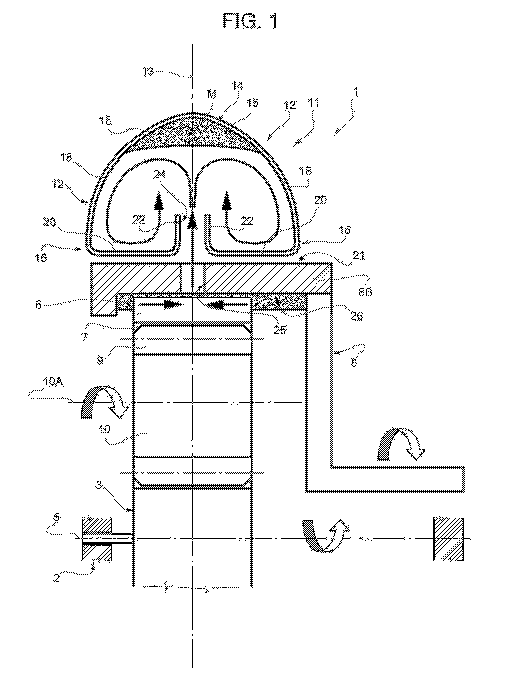
In figure 1 number 1 indicates, as a whole, a mechanical
gear transmission comprising a fixed support frame 2, which
is partially shown, an internal ring gear 3, generally for
the input of the motion, which is coupled to the frame 2 so
as to rotate around a fixed axis 5 relative to the frame 2
itself.
The transmission 1 also comprises, an external ring gear 6,
which is arranged coaxially to the axis 5 and has an
internal toothing 7.
In figure 1, the ring gear 6 is coupled to the frame 2 by
means of a rotary organ 8, which can rotate relative to the
frame 2 around the axis 5 and comprises a single-piece
tubular portion 8B, which houses, on the inside, and is
integrally connected to the ring gear 6 in a known manner.
In the transmission 1, the toothing 7 of the ring gear 6
engages with the toothing 9 of one or more intermediate
ring gears 10, which, in turn, engage with the central ring
gear 3 and rotate around respective axis 10A, which are
fixed relative to the frame 2 and parallel to the axis 5.
With reference to figure 1, the transmission 1 comprises,
finally, an annular collection collector or manifold 11 to
collect the lubricant oil of the ring gears 3, 6 and 10.
CA 02956059 2017-01-23
WO 2016/016877
PCT/1B2015/055890
The collection collector 11, which is part of a lubrication
circuit for the ring gears, is defined by an annular hollow
body, which is preferably manufactured in one single piece
of metal material or is made up of different portions made
5 of the same material or of different materials, which are
connected to each other in a known manner.
The collection collector 11 is stably connected, in a known
manner, to the frame 2 in a position surrounding the
tubular portion 8B.
In the embodiment described herein, the collection
collector 11 comprises two annular half-shells 12, which
are mirror-like relative to a radial plane 13, which is
orthogonal to the axis 5 and substantially passes through
the middle of the ring gears 3 and 10. According to a
variant that is not shown herein, the collection collector
11 does not have radial symmetry planes and the two half-
shells are different from one another in terms of geometry
and sizes, so as to adjust to the arrangement and to the
manufacturing features of the ring gears.
In the embodiment described herein, the collection
collector 11 comprises an external central concave portion
14, which is V-shaped and comprises, in turn, two sections
15, which extend starting from the plane 13 and each makes
up part of a relative half-shell 12.
The portion 14 has a concavity turned towards the ring gear
CA 02956059 2017-01-23
WO 2016/016877
PCT/1B2015/055890
6
6, so as to collect an oil mass M moved as a result of a
centrifugal effect. The collection collector 11 also
comprises, two lateral concave portions 16, which are
arranged on opposite sides of the plane 13 and each makes
up part of a respective half shell 12.
Each concave portion 16 has a concavity turned towards the
concave portion 14, houses, in use, a relative lubricant
oil mass, and is stably connected in a fluid-tight manner
to a respective section 15 of the concave portion 14 itself
by means of a relative wall 18 defining a deflector screen,
which is designed to channel a part of the oil drawn or is
present in the concave portion 14 on the inside of the
respective concave portion 16.
With reference to figure 1, each concave portion 16
comprises a relative bottom wall 20, which faces and is
arranged alongside an external circumferential surface 21
of the tubular portion 8, and a relative internal annular
wall 22, which is disc-shaped, faces the wall 22 of the
other concave portion 16 and delimits, with the other
radial wall 22, a unidirectional radial passage 24 to guide
the oil towards the inside of the collection collector 11.
The passage 24 is radially aligned with a further radial
passage 25, which is obtained through an external surface
21 of the tubular portion 8B and communicates with a
storage or transit chamber 26, which is obtained on the
CA 02956059 2017-01-23
WO 2016/016877
PCT/1B2015/055890
7
inside of the coupling element 8 and crosses the ring gear
6.
In the variant shown in figure 2, the tubular portion 8B
consists of two tubular bodies 8B1 and 8B2, which are
axially arranged alongside each other and are joined to
each other by a known coupling 27. The passage 25 extends
between the tubular bodies 8B1 and 8B2 and through the
coupling 27.
In the further variant shown in figure 3, two radial
passages 25, which are arranged alongside each other in an
axial direction, are obtained between the two tubular
bodies 8B1 and 8B2 and through the coupling 27. According
to a variant that is not shown herein, a plurality of
passages 25 are obtained between or through the two bodies
8B1 and 8B2, so as to channel the oil present in the
chamber 26 in the passage 24.
In use, during the rotation of the ring gear 6 at the
normal running speed, a part of the lubricant oil is
pushed, as a result of a centrifugal effect, towards the
tubular portion 8B and into the chamber 26, from which it
flows out through the passage/s 25 and enters the
collection collector 11 through the passage 24, thus
placing itself on the inside of the concave portion 14, as
shown in figures 1, 2 and 3. From the concave portion 14
the oil is then expelled, in a known manner, and
CA 02956059 2017-01-23
WO 2016/016877
PCT/1B2015/055890
8
reintroduced into the system.
When the rotation speed of the ring gear 6 and, hence, of
the ring gears 3 and 10 decreases, at least part of the oil
mass contained in portion 14 falls, due to gravity, towards
the ring gear 6, thus being collected in the concave
portions 16.
Owing to the above, it is evident that, whatever the speed
of rotation of the transmission, the drawn oil is always
confined on the inside of the collection collector 11 and
then returned, in a known manner, towards a collection
area, from which it is reintroduced into the system,
without significant leaks and without the risk for the
drawn oil to come into contact with rotary parts of the
transmission 1.
The embodiment shown in figure 4 relates to a transmission
30, which differs from the transmission 1 of figure 1
because of some manufacturing details and whose parts are
indicated, where possible, with the same reference numbers
as the corresponding parts of the transmission 1.
In the transmission 30, the ring gear or the ring gears 10
are coupled to the frame 2 by means of a coupling element
31, which extends coaxial to the axis 5 and rotates around
the axis 5 itself, preferably in a direction that is
contrary to the direction of rotation of the coupling
element 8 and corresponds to the direction of rotation of
CA 02956059 2017-01-23
WO 2016/016877
PCT/1B2015/055890
9
the ring gear 3.
The element 31 comprises a tubular portion 32, which
extends between the collection collector 11 and the tubular
body 8B coaxially to the axis 5. The tubular portion 32 has
an internal diameter that is greater than the external
diameter of the tubular body 8B and delimits an internal
annular chamber 33, which is designed to house a lubricant
liquid and communicates, on one side, with the passage 25
and, on the other side, with a passage 34, which, in turn,
communicates with the passage 24. In this specific case,
the chamber 26 is delimited by the tubular portion 8B and
by the ring gear 6 and the passages 25 and 34 are axially
not aligned.
Conveniently, the tubular portion 32 is made by means of
two bodies axially arranged alongside, like the tubular
portion 8B.
The particular way in which the collection collector 11 is
designed, on the one hand, prevents the use of mechanical
seals between the tubular portions 8B and 32 and the
collection collector 11 and, on the other hand, makes it
easier for the transmission to be assembled.
The embodiment shown in figure 5 relates to a transmission
40, which differs from the transmission 30 because of some
manufacturing details and whose parts are indicated, where
possible, with the same reference numbers as the
CA 02956059 2017-01-23
WO 2016/016877
PCT/1B2015/055890
corresponding parts of the transmission 1.
In the transmission 40, the coupling element 8 is stably
connected to the frame 2 so as to support the ring gear 6
in an axially and angularly fixed position relative to the
5 frame 2 itself, whereas the coupling element 31 extends on
the inside of the tubular portion 8B.
The transmission 40 comprises a collection collector 41,
which differs from the collection collector 11 in that the
two half-shells 12 are divided from each other along the
10 radial plane 13, are moved apart from each other and from
the plane 13, are arranged so as to project on opposite
axial sides of the tubular portion 8B, and extend in
positions facing the ring gear 6 and the ring gears 10, as
shown in figure 5.
In particular, each half-shell 12 has its own section 15
integrally connected to a respective axial end of the
tubular portion 8B, so as to define, with part of the
tubular portion 8B itself and of the ring gear 6, a
respective concave portion 14.
According to a variant that is not shown herein, one
section 15 or both sections 15 is or are directly or
indirectly connected to the frame 2.
Each half-shell 12 has its own concave portion 16 facing
the ring gears 10 and its own wall 18, which practically
faces the toothing 7 and 9 of the external ring gear 6 and
CA 02956059 2017-01-23
WO 2016/016877
PCT/1B2015/055890
11
of the ring gears 10.
As a consequence, each concave portion 16 is arranged with
its bottom wall 20 substantially parallel to the axis 5 or
slightly inclined relative to the axis 5 itself and, in
this specific case, alongside the axes 10A and with its
wall 22 extending towards the toothing 7 of the external
ring gear 6 and towards the ring gears 10. In this way,
each one of the walls 22 delimits, with the axial surfaces
of the ring gears 10, a respective radial inlet passage 42
to let the drawn oil into the relative half-shell 12.
Conveniently, the passage 42 is tapered in a radial
direction towards the external ring gear 6, so as to help
the drawn oil get into the relative half-shell 12 as a
result of a centrifugal effect and so as to inhibit or
obstacle the outflow of oil from the relative half-shell 12
as the speed of rotation of the coupling element 31 and of
the ring gears 10 decreases.
The presence of the walls 22 avoids any contact between the
drawn oil and the ring gears 10 or the coupling element 31
after the oil has entered the relative half-shell 12,
whereas the walls 18 intercept the oil splashes flowing out
of the toothing 7, 9, thus channelling them into one or the
other concave portion 14, 16.
Owing to the above, it is evident that transmissions 1, 30
and 40 described herein can be subject to changes and
CA 02956059 2017-01-23
WO 2016/016877
PCT/1B2015/055890
12
variations, without for this reason going beyond the scope
of protection set forth in the independent claims.
In particular, there can be a different number or different
types of ring gears and the half-shells 12 defining the
collection collector 11 could be different in terms of
geometry and/or sizes, but they are always such as to
collect and hold the mass of drawn oil, whatever the speed
of rotation, and to avoid any kind of return of the mass of
drawn oil towards the movable part of the transmission, as
the speed of rotation varies.