Note: Descriptions are shown in the official language in which they were submitted.
CA 02956587 2017-01-27
1
DESCRIPTION
WORK VEHICLE AND CONTROL METHOD FOR WORK VEHICLE
Field
[0001] The present invention relates to a work vehicle
and a control method for the work vehicle.
Background
[0002] In a work vehicle provided with a mechanical
travel device that travels by transmitting power generated
by an engine to a drive wheel via a transmission, control
that reduces drive force of an idling drive wheel is
executed in order to improve travel performance. Such
control is called traction control. In Patent Literature
1, disclosed is a technology in which traction control is
achieved by reducing drive force of a drive wheel by using
a brake.
Citation List
Patent Literature
[0003] Patent Literature 1: WO 2010/074225
Summary
Technical Problem
[0004] In the case of making a mechanical work vehicle
travel, a drive wheel may not recover from slipping despite
actuation of traction control by using a brake.
[0005] The present invention is directed to making the
drive wheel recover from slipping and allowing the
mechanical work vehicle to continue traveling.
Solution to Problem
[0006] According to the present invention, a work
vehicle comprises: an engine; a plurality of drive wheels
driven by the engine; and an operation controller
configured to execute first drive force control that brakes
a slipping drive wheel out of the plurality of drive wheels
and also configured to execute second drive force control
CA 02956587 2017-01-27
2
that reduces output of the engine in accordance with a slip
ratio of the slipping drive wheel during execution of the
first drive force control.
[0007] It is preferable that the operation controller
executes the second drive force control in a case where an
actual vehicle speed of the work vehicle is less than a
first vehicle speed threshold and also a speed difference
between the drive wheel and a driven wheel included in the
work vehicle is continuously kept at a speed difference
threshold or more.
[0008] It is preferable that the operation controller
finishes the second drive force control currently executed
in a case where the first drive force control is finished
or the actual vehicle speed of the work vehicle is equal to
or more than a second vehicle speed threshed that is larger
than the first vehicle speed threshold during execution of
the second drive force control.
[0009] It is preferable that the work vehicle further
comprises a communication device configured to communicate
with outside of the work vehicle, wherein the operation
controller obtains a target vehicle speed of the work
vehicle from the communication device, performs control
such that the actual vehicle speed of the work vehicle
becomes the target vehicle speed, and at a time of
performing the second drive force control, subtracts a
correction accelerator position acquired in accordance with
a slip ratio of the slipping drive wheel from a target
accelerator position of an accelerator acquired in
accordance with the target vehicle speed and the actual
vehicle speed, the accelerator adjusting output of the
engine.
[0010] According to the present invention, a work
vehicle including an engine and a plurality of drive wheels
3
driven by the engine, comprises: a communication device
configured to communicate with outside of the work vehicle;
and an operation controller configured to obtain a target
vehicle speed of the work vehicle from the communication
device and perform control such that an actual vehicle speed
of the work vehicle becomes the target vehicle speed, wherein
the operation controller executes first drive force control
that brakes a slipping drive wheel out of the plurality of
drive wheels such that a slip ratio of the slipping drive
wheel becomes a target value of the slip ratio of the drive
wheel, and further executes second drive force control that
reduces output of the engine in accordance with the slip
ratio of the slipping drive wheel during execution of the
first drive force control.
[0011] According to the present invention, a control
method for a work vehicle including an engine and a plurality
of drive wheels driven by the engine, comprises: acquiring
slip ratios of the plurality of drive wheels; executing drive
force control that brakes a slipping drive wheel out of the
plurality of drive wheels; reducing output of the engine in
accordance with a slip ratio of the slipping drive wheel in a
case where a vehicle speed of the work vehicle is less than a
vehicle speed threshold and a speed difference between the
drive wheel and a driven wheel included in the work vehicle
is continuously kept at a speed difference threshold or more
during execution of the drive force control.
[0011a] In a further aspect of the invention, there is
provided a dump truck for traveling in a mine including: an
engine; a vessel; a plurality of drive wheels driven by the
engine; and an operation controller configured to execute
first drive force control that brakes a slipping drive wheel
out of the plurality of drive wheels and also configured to
execute second drive force control that reduces output of the
CA 2956587 2018-06-11
3a
engine in accordance with a slip ratio of the slipping drive
wheel during execution of the first drive force control,
wherein at a time of performing the second drive force
control, the operation controller subtracts a correction
accelerator position acquired in accordance with the slip
ratio of the slipping drive wheel from a target accelerator
position of an accelerator acquired in accordance with a
target vehicle speed and an actual vehicle speed.
[0011b] In a further aspect of the invention, there is
provided a dump truck including an engine and a plurality of
drive wheels driven by the engine, including: a communication
device configured to communicate with outside of the dump
truck; and an operation controller configured to obtain a
target vehicle speed of the dump truck from the communication
device and perform control such that an actual vehicle speed
of the dump truck becomes the target vehicle speed, wherein
the operation controller executes first drive force control
that brakes a slipping drive wheel out of the plurality of
drive wheels such that a slip ratio of the slipping drive
wheel becomes a target value of the slip ratio of the drive
wheel, and further executes second drive force control that
reduces output of the engine in accordance with the slip
ratio of the slipping drive wheel during execution of the
first drive force control, and at a time of performing the
second drive force control, the operation controller
subtracts a correction accelerator position acquired in
accordance with the slip ratio of the slipping drive wheel
from a target accelerator position of an accelerator acquired
in accordance with the target vehicle speed and the actual
vehicle speed.
[0011c] In a further aspect of the invention, there is
provided a control method for a dump truck including an
engine and a plurality of drive wheels driven by the engine,
CA 2956587 2018-06-11
3b
including: acquiring slip ratios of the plurality of drive
wheels; executing drive force control that brakes a slipping
drive wheel out of the plurality of drive wheels; reducing
output of the engine in accordance with a slip ratio of the
slipping drive wheel in a case where a vehicle speed of the
dump truck is less than a vehicle speed threshold and a speed
difference between the drive wheel and a driven wheel
included in the dump truck is continuously kept at a speed
difference threshold or more during execution of the drive
force control; and subtracting a correction accelerator
position acquired in accordance with the slip ratio of the
slipping drive wheel from a target accelerator position of an
accelerator acquired in accordance with a target vehicle
speed and an actual vehicle speed.
[0012] The present invention makes the drive wheel to
recover from slipping and enables a mechanical work vehicle
to continue traveling.
Brief Description of Drawings
[0013] FIG. 1 is a diagram illustrating a site where a
work vehicle according to the present embodiment works.
CA 2956587 2018-06-11
CA 02956587 2017-01-27
FIG. 2 is a diagram illustrating a dump truck
according to the present embodiment.
FIG. 3 is a block diagram illustrating a control
system included in the dump truck.
FIG. 4 is a flowchart illustrating a procedure at the
time of executing a control method for the work vehicle
according to the present embodiment.
FIG. 5-1 is a diagram illustrating a relation between
a slip ratio SR and friction force.
FIG. 5-2 is a diagram illustrating a rear wheel that
is a drive wheel and a road surface where the rear wheel
contacts.
FIG. 6 is a block diagram illustrating an output
suppression arithmetic unit.
FIG. 7 is a block diagram illustrating a correction
accelerator position calculation unit.
FIG. 8 is a flowchart illustrating processing at the
time of finishing second drive force control.
FIG. 9 is a block diagram illustrating a correction
accelerator position calculation unit.
FIG. 10 is an exemplary fuzzy table.
Description of Embodiments
[0014] A mode (embodiment) to implement the present
invention will be described with reference to the drawings.
[0015] FIG. 1 is a diagram illustrating a site where a
work vehicle according to the present embodiment works.
The work vehicle of the present embodiment is used for
various kinds of works in a mine, but the work vehicle is
not limited to the one used in a mine. In the present
embodiment, exemplified as a work vehicle is a dump truck
10 provided as a transportation vehicle to transport
crushed stones, or soils, rocks, and the like generated at
the time of excavating crushed stones, but the work vehicle
CA 02956587 2017-01-27
is not limited thereto. For example, the work vehicle
according to the present embodiment may be a wheel loader
and the like. The work vehicle may be an autonomous travel
vehicle that generates an own travel route by itself and
5 travels.
[0016] <Dump Truck in Mine>
In the present embodiment, the dump truck 10 is
controlled by an unmanned dump operation system 1 and
automatically travels. In the unmanned dump operation
system 1, an operation management device 2 transmits, to
the dump truck 10, necessary information for automatic
operation, such as a destination of the dump truck 10, a
travel permission per zone, positional information of other
vehicles, and an emergency stop command. The dump truck 10
automatically travels based on the information necessary
for automatic operation obtained from the operation
management device 2. Different from the dump truck 10 that
is a movable body, the operation management device 2 is a
kind of a management device installed in, for example, a
management facility in a mine and adapted to manage a work
vehicle like the dump truck 10, administration of the mine,
and so on.
[0017] The operation management device 2 is connected to
a radio communication device 4 including an antenna 4A in
order to make the dump truck 10 that works in the mine
travel. The dump truck 10 includes an antenna 17A in order
to receive a command from the operation management device 2
and transmit own work information to the operation
management device 2. Besides, the dump truck 10 receives
radio waves from a global positioning system (GPS)
satellites 5A, 5B, 50 by a GPS antenna 18A and can perform
positioning for an own position.
[0018] Output of radio waves transmitted by the antenna
CA 02956587 2017-01-27
6
4A of the operation management device 2 and the antenna 17A
of the dump truck 10 is not in a communicable range that
can cover an entire area of the mine. Therefore, the
unmanned dump operation system 1 includes a repeater 3 that
relays the radio waves transmitted by the antenna 4A and
the antenna 17A. The operation management device 2 can
transmit, via the repeater 3, a command for controlling the
dump truck 10 that is working at a position distant from
the own position of the operation management device, and
also can collect the work information from the dump truck
10. In the mine, the dump truck 10 travels on a flat road
FR and also travels on a sloping road RS at the time of
traveling between a soil unloading place and a loading
place. Next, the dump truck 10 will be described.
[0019] <Dump Truck 10>
FIG. 2 is a diagram illustrating the dump truck 10
according to the present embodiment. The dump truck 10 is
controlled by the unmanned dump operation system 1 and
automatically works even without operation by an operator.
However, in the case where the dump truck 10 is delivered
to a maintenance factory or in the case where the dump
truck 10 is carried out from the maintenance factory,
control of the dump truck 10 by the unmanned dump operation
system 1 may not be executed. In this case, an operator
needs to ride in the dump truck 10 and operate the dump
truck 10. Therefore, the dump truck 10 includes an
operating room 11DR in which the operator rides, and the
operating room 11DR includes operating devices such as a
steering wheel, an accelerator pedal, and a brake pedal.
[0020] The dump truck 10 loads matters to be loaded and
unloads the loaded matters at a desired place. The dump
truck 10 includes: a vehicle body 11; a vessel 12; front
wheels 13F; rear wheels 13R; a brake 13B as a braking
CA 02956587 2017-01-27
7
device; a suspension cylinder 14; a rotation sensor 15; a
suspension pressure sensor (pressure sensor) 16; an in-
vehicle radio communication device 17E connected to the
antenna 17A; a GPS receiver 18B as a positional information
detection device connected to the GPS antenna 18A; a
communication controller 19; a control system 20; and a
drive device 30. Meanwhile, the dump truck 10 is provided
with various kinds of mechanisms and functions included in
a general carrier or transportation vehicle in addition to
above-described equipment. In the present embodiment,
illustrated is a rigid type dump truck 10 in which steering
is perfoLmed by the front wheels 13F, but instead of such
an dump truck 10, the present embodiment may also be
applicable to an articulate type dump truck in which a
vehicle body is divided into a front portion and a rear
portion and these portions are joined by a free joint.
[0021] The vehicle body 11 includes the vessel 12, front
wheels 13F, rear wheels 13R, suspension cylinder 14, drive
device 30, and the like. The vessel 12 functions as a
loading platform to load minerals, soils, and the like as
the loaded matters. The vessel 12 is disposed at an upper
portion of the vehicle body 11. The front wheels 13F are
steering wheels to define a moving direction of the dump
truck 10. The rear wheels 13R are drive wheels that makes
the dump truck 10 travel. The front wheels 13F are
disposed on a front side of the vehicle body 11, namely,
both right and left sides of the operating room 11DR side.
The rear wheels 13R are disposed on a rear side of the
vehicle body 11, namely, both right and left sides on the
opposite side of the operating room 11DR.
[0022] The brake 13B is to include a front wheel brake
13BF and a rear wheel brake 13BR. The front wheel brake
13BF is provided at each of the front wheels 13F and brakes
CA 02956587 2017-01-27
8
these front wheels. The rear wheel brake 13BR is provided
at each of the rear wheels 13R and brakes these rear
wheels.
[0023] The suspension cylinders 14 are provided in
between the vehicle body 11 and the right and left front
wheels 13F and between the vehicle body 11 and the right
and left rear wheels 13R respectively. The suspension
cylinders 14 are installed at the right and left front
wheels 13F and the right and left rear wheels 13R
respectively and adapted to support these wheels. To the
suspension cylinders 14, not only loads of the vehicle body
11 and the vessel 12 but also a load corresponding to mass
of loaded matters at the time of loading the loaded matters
are applied. Hydraulic oil is sealed inside the suspension
cylinder 14, and extends/contracts in accordance with the
mass of the loaded matters.
[0024] The rotation sensor 15 is to include a front
wheel side rotation sensor 15F adapted to detect an engine
speed of each front wheel 13F, and a rear wheel side
rotation sensor 15R adapted to detect an engine speed of
each rear wheels 13R. For example, the front wheel side
rotation sensor 15F detects a rotation speed of the front
wheel 13F, thereby the rotation sensor 15 measuring a
traveling speed of the dump truck 10 (suitably referred to
as vehicle speed). The rotation sensor 15 may be, for
example, a pulse sensor. The front wheel 13F is a driven
wheel not driven by the drive device 30. While the dump
truck 10 is driven and traveling, namely, while the rear
wheels 13R are driven by the drive device 30 and the dump
truck 10 is traveling, the front wheel 13F is not driven by
the drive device 30. Therefore, slipping does not
substantially occur with the road surface. Accordingly,
the rotation speed of the front wheel 13F substantially
CA 02956587 2017-01-27
9
corresponds to the vehicle speed of the dump truck 10.
[0025] The suspension pressure sensors 16 are provided
at the respective corresponding suspension cylinders 14
installed at the front wheels 13F and the rear wheels 13R
respectively. The suspension pressure sensor 16 detects a
load applied to each of the suspension cylinders 14.
Specifically, the suspension pressure sensor 16 can measure
mass of loaded matters (loaded amount) by detecting
pressure of the hydraulic oil sealed in the suspension
cylinder 14.
[0026] A communication device 19S includes the antenna
17A, in-vehicle radio communication device 17B, GPS antenna
18A, and GPS receiver 18B, and communication controller 19.
The antenna 17A receives radio waves output from the
repeater 3 of the operation management device 2 illustrated
in FIG. 1. The antenna 17A outputs the received radio
waves to the in-vehicle radio communication device 17B.
The in-vehicle radio communication device 17B performs
radio communication via the antenna 17A, repeater 3, and
antenna 4A of the operation management device 2.
[0027] The GPS antenna 18A receives radio waves output
from the plurality of GPS satellites 5A, 5B, 5C
constituting the global positioning system (GPS) and
illustrated in FIG. 1. The GPS antenna 18A outputs the
received radio waves to the GPS receiver 18B. The GPS
receiver 18B converts the radio waves received by the GPS
antenna 18A to an electric signal, and calculates
positional information of the GPS antenna 18A, namely, the
positional information of the dump truck 10. Thus, the GPS
receiver 18B performs positioning for the position of the
dump truck 10.
[0028] The in-vehicle radio communication device 17B and
the GPS receiver 18B are connected to the communication
CA 02956587 2017-01-27
=
controller 19. The communication controller 19 is
connected to the control system 20. The communication
controller 19 converts the information from the in-vehicle
radio communication device 17B and the GPS receiver 18B to
5 a format understandable by the control system 20. The
control system 20 obtains, from the operation management
device 2, information in order to drive the dump truck 10
in an unmanned state via the communication controller 19,
in-vehicle radio communication device 17B, and antenna 17A.
10 Additionally, the control system 20 obtains the positional
information of the dump truck 10 from the GPS receiver 18B.
(0029] (Drive Device 30)
The drive device 30 drives the rear wheels 13R and
makes the dump truck 10 travel. The drive device 30
includes an engine 31 as a power generation source, a
torque converter 32, a gear box 33, a propeller shaft 34,
and a differential gear 35. The engine 31 is a diesel
engine in the present embodiment, but not limited to the
diesel engine. Output of the engine 31 is transmitted to
the gear box 33 via the torque converter 32. The torque
converter 32 includes: an input shaft adapted to receive
output of the engine 31; and an output shaft adapted to
output the output of the engine received in the input
shaft. The torque converter 32 includes a lock-up clutch
32C that directly connects the input shaft to the output
shaft. The gear box 33 reduces a rotation speed (engine
speed per unit time) of a crankshaft that is the output
shaft of the engine 31, increases torque, and outputs the
same to the propeller shaft 34.
[0030] The propeller shaft 34 connects an output unit
33o of the gear box 33 to an input unit 35i of the
differential gear 35. The propeller shaft 34 transmits
output of the gear box 33 to the differential gear 35. The
CA 02956587 2017-01-27
4
11
differential gear 35 transmits the transmitted output from
the gear box 33 to the right and left rear wheels 13R and
drives these wheels. Thus, the drive device 30 makes the
dump truck 10 travel.
[0031] (Gear Box 33)
The gear box 33 can perform output from the output
unit 330 by varying the rotation speed of the engine 31
received from an input unit 331, namely, by changing the
gear. In the present embodiment, the gear box 33 is, for
example, a power transmission device in which a plurality
of planetary gear mechanisms adapted to transmit power from
the engine 31 is combined with a plurality of clutches and
a plurality of brakes to select a rotary element included
in each of the planetary gear mechanisms. The gear box 33
can achieve a plurality of different transmission gear
ratios by switching the rotary element where the power of
the engine 31 passes by engaging or releasing the above-
described clutch and brake. Thus, in the present
embodiment, the dump truck 10 is a mechanical vehicle that
travels by transmitting, to the rear wheels 13R, the power
generated by the engine 31 via the torque converter 32,
gear box 33, propeller shaft 34, and differential gear 35.
[0032] <Control System 20>
FIG. 3 is a block diagram illustrating the control
system 20 included in the dump truck 10. The control
system 20 includes a first control system 40 and a second
control system 50. The first control system 40 controls
the equipment such as the engine 31, gear box 33, and brake
13B mounted on the dump truck 10. The first control system
40 makes the dump truck 10 travel based on operation by an
operator riding in the dump truck 10. The second control
system 50 generates a control command to control the dump
truck 10 based on a command from the operation management
CA 02956587 2017-01-27
12
device 2 illustrated in FIG. 1 and information obtained
from the communication device 19S. The second control
system 50 transmits the generated control command to the
first control system 40 and makes the dump truck 10
automatically travel in an manned state via the first
control system 40.
[0033] In the present embodiment, an operation mode in
which the dump truck travels by operation of the operator
riding in the dump truck 10 is referred to as a first
operation mode. An operation mode in which the dump truck
10 travels without the operator riding in the dump truck
10, for example, the dump truck 10 travels based on
information from the outside of the dump truck 10 is
referred to as a second operation mode. The first
operation mode is the operation mode in which the dump
truck 10 travels in a manned state, and the second
operation mode is the operation mode in which the dump
truck 10 travels in an unmanned state.
[0034] (First Control System 40)
The first control system 40 includes, for example, a
transmission (TM) controller 41, a brake controller 42, an
engine controller 43, an antilock brake system (ABS)
controller 44, a monitor 60M, and an information collection
device 601. The TM controller 41, brake controller 42,
engine controller 43, ABS controller 44, monitor 60M, and
information collection device 601 are computers each
including: a processing unit having a central processing
unit (CPU) and the like; and a storage unit such as a read
only memory (ROM), for example.
[0035] The TM controller 41 controls the gear box 33 and
the lock-up clutch 32C of the torque converter 32
illustrated in FIG. 2. The brake controller 42 controls
the brake 13B illustrated in FIG. 2. The engine controller
CA 02956587 2017-01-27
13
43 controls the engine 31 illustrated in FIG. 2. In the
case where the front wheels 13F and the rear wheels 13R are
locked when the brake 13B illustrated in FIG. 2 brakes
these wheels, the ABS controller 44 reduces brake force of
the brake 13B and releases the locked front wheels 13F and
rear wheels 13R.
[0036] The information collection device 601 obtains
information related to a state of the dump truck 10 from
the TM controller 41, brake controller 42, engine
controller 43, ABS controller 44, and various kinds of
sensors while the dump truck 10 is working, and stores the
information correlated to time of obtaining the
information. The information in which the state of the
dump truck 10 and the information correlated to the time of
obtaining the information will be referred to as the work
information. The information collection device 601
transmits the work information of the dump truck 10 to the
operation management device 2 illustrated in FIG. 1 via the
communication device 19S. The operation management device
2 creates a daily report by using the work information
obtained from the information collection device 601 and
detects malfunction and the like of the dump truck 10, for
example. In the present embodiment, the in-vehicle radio
communication device may be directly connected to the
information collection device 611, and the information
collection device 611 may also transmit the work
information to the operation management device 2 not from
the communication device 19S but via the in-vehicle radio
communication device.
[0037] The monitor 60M displays various kinds of
information of the dump truck 10. In the various kinds of
information, for example, a vehicle speed of the dump truck
10, namely, a traveling speed of the dump truck 10, a
CA 02956587 2017-01-27
14
temperature of cooling water of the engine 31 illustrated
in FIG. 2, various kinds of alarms, and the like are
included. The various kinds of information displayed on
the monitor 60M includes, for example, necessary
information for an operator who operates the dump truck in
the case where the dump truck 10 travels in the first
operation mode.
[0038] The TM controller 41, brake controller 42, engine
controller 43, ABS controller 44, monitor 60M, and
information collection device 601 store computer programs
to implement the respective functions in the respective
storage unit. In the TM controller 41, brake controller
42, engine controller 43, ABS controller 44, monitor 60M,
and information collection device 601, the respective
processing units read, from the respective storage units,
the computer programs necessary for control, and execute
commands described in the computer programs, thereby
controlling the equipment mounted on the dump truck 10.
[0039] A shift selector 46 is connected to the TM
controller 41. The shift selector 46 designates a variable
speed level of the gear box 33 illustrated in FIG. 2 and
designates a variable speed mode in the case where the gear
box 33 automatically changes the speed. Furthermore, in
the case of the second operation mode, the TM gear box 41
controls the gear box 33 in accordance with a control
command from the second control system 50. A brake sensor
47A and a hoist sensor 47B are connected to the brake
controller 42. The brake sensor 47A detects an operation
amount of at least one of a retarder lever and the brake
pedal provided in the operating room 11DR of the dump truck
10. The brake controller 42 controls a braking state of
the brake 13B of the dump truck 10 based on a detection
value of the brake sensor 47A. The brake controller 42
CA 02956587 2017-01-27
makes the brake 13B of the dump truck 10 actuate when
operation made to a hoist lever is detected by the hoist
sensor 47B. Additionally, in the case of the second
operation mode, the brake controller 42 controls the brake
5 13B in accordance with a control command from the second
control system 50.
[0040] An accelerator position sensor 48 is connected to
the engine controller 43. The accelerator position sensor
48 detects an operation amount of the accelerator pedal
10 provided in the operating room 11DR of the dump truck 10.
The engine controller 43 controls the engine 31 of the dump
truck 10 based on an accelerator position command ACO that
is a detection value of the accelerator position sensor 48.
Additionally, in the case of the second operation mode, the
15 engine controller 43 controls the engine 31 in accordance
with a control command from the second control system 50.
The rotation sensors 15 (front wheel side rotation sensor
15F and rear wheel side rotation sensor 15R) are connected
to the ABS controller 44. The ABS controller 44 adjusts
the brake force of the brake 13B based on detection values
of the rotation sensors 15.
[0041] As the front wheel side rotation sensor 15F,
there are: a left front wheel rotation sensor 15FL adapted
to detect an engine speed of the front wheel on the left
side; and a right front wheel rotation sensor 15FR adapted
to detect an engine speed of the front wheel on the right
side. As the rear wheel side rotation sensor 15R, there
are: a left rear wheel rotation sensor 15RL adapted to
detect an engine speed of the left-side rear wheel; and a
right rear wheel rotation sensor 15RR adapted to detect an
engine speed of the right-side rear wheel.
[0042] As illustrated in FIG. 3, the TM controller 41,
brake controller 42, engine controller 43, ABS controller
CA 02956587 2017-01-27
16
44, monitor 60M, and information collection device 601 are
electrically connected by a communication line 45. With
this configuration, these components can mutually exchange
information via the communication line 45. For example,
the TM controller 41, brake controller 42, engine
controller 43, and ABS controller 44 can obtain, via the
communication line 45, information of other control units
and detection values of sensors connected to other control
units, and use the same for own control.
[0043] (Second Control System 50)
The second control system 50 includes, for example, an
operation controller 51, an interface controller 52, a
safety controller 53, a recording device 54, and a
peripheral monitoring device 55. The operation controller
51, interface controller 52, safety controller 53,
recording device 54, and peripheral monitoring device 55
are computers each including: a processing unit having a
central processing unit (CPU) and the like; and a storage
unit such as a read only memory (ROM), for example.
[0044] The operation controller 51 controls the dump
truck 10 via the first control system 40 based on
information obtained via the communication controller 19
and used to operate the dump truck 10 from the operation
management device 2 in the second operation mode. In the
operation controller 51, various kinds of sensors such as a
gyro sensor 61, a vehicle speed sensor 62, a steering angle
sensor 63, the left front wheel rotation sensor 15FL, the
right front wheel rotation sensor 15FR, the left rear wheel
rotation sensor 15RL, and the right rear wheel rotation
sensor 15RR are connected. An acceleration speed sensor 64
is connected to the brake controller 42. The operation
controller 51 obtains the information detected by the
above-described various kinds of sensors, and makes the
CA 02956587 2017-01-27
17
dump truck 10 automatically travel in the second operation
mode. In the present embodiment, the operation controller
51 includes a timer 51M inside thereof. The timer 51M is
used at the time determining whether to execute second
drive force control described later.
[0045] The interface controller 52 is connected to a
communication line 45 of the first control system 40 by a
communication line 21. The interface controller 52
monitors a state of the first control system 40 via the
communication line 21. Furthermore, the interface
controller 52 transmits information from the second control
system 50 to the first control system 40 after converting
the same in a format understandable by the first control
system 40, for example, converting a communication
protocol, and also transmits information from the first
control system 40 to the second control system 50 after
converting the same in a format understandable by the
second control system 50. The safety controller 53
controls a headlight, a blinker, a horn, an engine starter,
and a parking brake, and the like of the dump truck 10.
The recording device 54 records, for example, a travel
route of the dump truck 10 by recoding a position of the
dump truck 10 obtained from the GPS receiver 18B in a
manner correlated to time elapsed.
[0046] The peripheral monitoring device 55 includes, for
example, a radar sensor and a laser sensor, and detects an
object existing ahead in a moving direction or in the
periphery of the dump truck 10. In the case where the dump
truck 10 travels in the second operation mode, the
operation controller 51 and the safety controller 53
actuates the brake 13B of the dump truck 10 to stop the
dump truck 10 based on object information detected by the
peripheral monitoring device 55. Meanwhile, the operation
CA 02956587 2017-01-27
18
controller 51 and the safety controller 53 may reduce
output of the engine 31 and may also steer the front wheels
13F. For example, in the case an object is detected ahead
in the moving direction of the dump truck 10, the operation
controller 51 avoids collision with the object by actuating
the brake 13B of the dump truck 10 to reduce a speed or
stop the dump truck 10 and by steering the front wheels
13F. Furthermore, in the case where darkness in the
periphery is detected by the peripheral monitoring device
55, the safety controller 53 may turn on the headlight of
the dump truck 10.
[0047] The operation controller 51, interface controller
52, and safety controller 53 store, in the respective
storage units, computer programs to implement the
respective functions. The operation controller 51,
interface controller 52, and safety controller 53 control
the dump truck 10 by respective processing units reading
the computer programs necessary for control from the
respective storage units and executing commands described
in the computer programs.
[0048] The operation controller 51, interface controller
52, and safety controller 53 are electrically connected by
a communication line 56. With this configuration, these
components can mutually exchange information. For example,
the operation controller 51, interface controller 52, and
safety controller 53 can obtain information of other
control units or detection values of sensors connected to
other control units via the communication line 56, and use
the same for processing.
[0049] The communication line 56 is connected to the
communication controller 19. The operation controller 51
obtains, from the communication controller 19 via the
communication line 56, information transmitted by the
CA 02956587 2017-01-27
19
operation management device 2 illustrated in FIG. 1 and
used to automatically operate the dump truck 10 in the
second operation mode. Additionally, the second control
system 50 transmits, to the operation management device 2,
information related to the state of the dump truck 10 that
is performing automatic operation in the second operation
mode, via the communication line 56 and the communication
controller 19. The TM controller 41 of the first control
system 40, engine controller 43, brake controller 42, and
ABS controller 44 can obtain information detected by the
various kinds of sensors such as the gyro sensor 61 and the
vehicle speed sensor 62 connected to the operation
controller 51 of the second control system 50 via the
communication line 56, interface controller 52,
communication line 21, and the communication line 45.
[0050] The operation controller 51, safety controller
53, recording device 54, and peripheral monitoring device
55 are electrically connected via a communication line 57.
With this configuration, these components can mutually
exchange information. The operation controller 51,
interface controller 52, and recording device 54 obtain,
for example, information related to an object existing in
the periphery of the dump truck 10 detected by the
peripheral monitoring device 55 via the communication line
57, and can use the information for control in the second
operation mode.
[0051] The operation controller 51 generates an
accelerator position command AGO, a shift control command
SLC, and a brake command BRC, and transmits the same to the
first control system 40 via the communication line 56,
interface controller 52, and communication line 21. The
engine controller 43 of the first control system 40 obtains
the accelerator position command ACO and controls output of
CA 02956587 2017-01-27
the engine 31 illustrated in FIG. 2. The TM controller 41
of the first control system 40 obtains the shift control
command SLC and the accelerator position command ACO, and
changes a variable speed level of the gear box 33
5 illustrated in FIG. 2. In the first operation mode, the TM
controller 41 obtains, from the engine controller 43, the
accelerator position command ACO that is a detection value
detected by the accelerator position sensor 48. In the
second operation mode, the TM controller 41 obtains, from
10 the communication line 45, the accelerator position command
ACO generated by the operation controller 51 of the second
control system 50. The brake controller 42 of the first
control system 40 obtains the brake command BRC and
controls the brake 13B illustrated in FIG. 2.
15 [0052] In the case where the dump truck 10 is made to
perform automatic operation in the second operation mode,
the operation controller 51 generates at least one of the
accelerator control command ACO, shift control command SLC,
and brake command BRC based on the information obtained
20 from the operation management device 2 and used to operate
the dump truck 10 in the second operation mode. Then, the
operation controller 51 controls the dump truck 10 via the
first control system 40 in accordance with at least one of
the accelerator control command ACO, shift control command
SLC, and brake command BRC.
[0053] <Drive Force Control>
In the case where the rear wheel 13R that is the drive
wheel of the dump truck 10 illustrated in FIG. 2 idles,
namely, slips in the second operation mode, the operation
controller 51 executes control to suppress slipping by
reducing force with which the drive device 30 of the dump
truck 10 drives the rear wheel 13R. Such control is
referred to as drive force control or traction control.
CA 02956587 2017-01-27
21
The force with which the drive device 30 drives the rear
wheel 13R will be referred to as driven force of the rear
wheel 13R.
[0054] The drive force control includes: suppressing
slipping by actuating the rear wheel brake 13BR and
reducing the drive force for the rear wheel 13R; and
suppressing slipping by reducing the drive force for the
rear wheel 13R by reducing output of the engine 31
illustrated in FIG. 2. In the following, the drive force
control using the rear wheel brake 13BR will be referred to
as first drive force control, and the drive force control
to reduce output of the engine 31 will be referred to as
second drive force control.
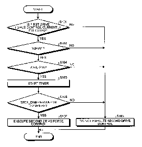
[0055] <Control Method for Work Vehicle>
FIG. 4 is a flowchart illustrating a procedure at the
time of executing a control method for the work vehicle
according to the present embodiment. The control method
for the work vehicle according to the present embodiment is
executed by the control system 20 illustrated in FIG. 3.
In the following, described is a case where the control
system 20 makes the dump truck 10 perform automatic
operation in the second operation mode, but it may also be
a case where the dump truck 10 travels in the first
operation mode in accordance with operation by an operator.
[0056] In Step S101, the operation controller 51 of the
second control system 50 determines whether the first drive
force control is currently executed. The first drive force
control is achieving by the brake controller 42 of the
first control system 40 illustrated in FIG. 3 actuating the
rear wheel brake 13BR that is the drive wheel illustrated
in FIG. 2 and reducing the drive force for the rear wheels
13R.
[0057] While the first drive force control is executed,
CA 02956587 2017-01-27
22
the brake controller 42 outputs, to the communication line
45, information indicating that the first drive force
control is currently executed. The operation controller 51
of the second control system 50 illustrated in FIG. 3 can
obtain the information indicating that the first drive
force control is currently executed via the communication
line 45, communication line 21, interface controller 52,
and communication line 56. The operation controller 51
determines whether the first drive force control is
currently executed based on this information.
[00581 (First Drive Force Control)
In the present embodiment, the first drive force
control is control to brake a slipping wheel out of the
left-side rear wheel 13R and the right-side rear wheel 13R
which are the plurality of drive wheels such that a slip
ratio of the slipping wheel becomes a target value of the
slip ratio of the drive wheel, namely, the rear wheel 13R.
In the following, the target value of the slip ratio will
be suitably referred to as a target slip ratio.
[0059] FIG. 5-1 is a diagram illustrating a relation
between a slip ratio SR and friction force TF. FIG. 5-2 is
a diagram illustrating the rear wheel 13R that is the drive
wheel and a road surface RD where the rear wheel 13R
contacts. In the following, a target slip ratio used in
the first drive force control will be referred to as a
first target slip ratio SRT1, and a target slip ratio used
in the second drive force control described later will be
referred to as a second target slip ratio SRT2. The first
target slip ratio SRT1 is, for example, about 0.35 while
the second target slip ratio SRT2 is, for example, about
0.6. Thus, the second target slip ratio SRT2 is a value
larger than the first target slip ratio SRT1. The friction
force TF in FIG. 5-1 is force generated between the rear
CA 02956587 2017-01-27
23
wheel 13R and the road surface where the rear wheel 13R
contacts as illustrated in FIG. 5-2. Provided that a
rotation speed of the rear wheel 13R is Vw and an actual
vehicle speed of the dump truck 10 is Vd, the slip ratio SR
is represented by a Formula (1).
SR = (Vw - Vd)/Vw (1)
[0060] The actual vehicle speed Vd of the dump truck is
a speed when the dump truck 10 is actually traveling. As
the actual vehicle speed Vd, for example, a detection value
of the vehicle speed sensor 62 illustrated in FIG. 3 is
used. Besides that, as the actual vehicle speed Vd, an
integration value of a detection value of the acceleration
speed sensor 64 illustrated in FIG. 3, or a value acquired
from a position of the dump truck 10 obtained from the GPS
receiver 18B illustrated in FIG. 3 may also be used. The
rotation speed Vw of the rear wheel 13R can be acquired
from a detection value of the rear wheel side rotation
sensor 15R illustrated in FIGS. 2 and 3. Since there are
the left side rear wheel 13R and the right side rear wheel
13R as the rear wheels 13R, the rotation speed Vw of the
rear wheel 13R is independently acquired on each of the
left side and the right side. A rotation speed Vwl of the
left-side rear wheel 13R is acquired from a detection value
of the left rear wheel rotation sensor 15RL illustrated in
FIG. 3, and a rotation speed Vwr of the right-side rear
wheel 13R is acquired from a detection value of the right
rear wheel rotation sensor 15RR illustrated in FIG. 3.
[0061] As illustrated in FIG. 5-2, a rotation center
axis of the rear wheel 13R is defined as Y-axis, an axis
orthogonal to the Y-axis and parallel to a tangential
direction of the rear wheel 13R at a portion where the rear
wheel 13R contacts the road surface RD is defined as X-
axis, and an axis orthogonal to both of the X-axis and the
CA 02956587 2017-01-27
24
Y-axis is defined as Z-axis. An LF direction is a
direction parallel to the X-axis of the rear wheel 13R and
parallel to the road surface RD at the portion where rear
wheel 13R contacts, and an SF direction is a direction
parallel to the Y-axis of the rear wheel 13R and also
parallel to the road surface RD where the rear wheel 13R
contacts.
[0062] The friction force TF in the LF direction, which
is generated between the rear wheel 13R and the road
surface RD, is drive force for the rear wheel 13R. The
drive force of the rear wheel 13R is also referred to as
traction force. The friction force TF in the SF direction,
which is generated between the rear wheel 13R and the road
surface RD, is side force, namely, lateral force for the
rear wheel 13R. In the following, the drive force will be
suitably referred to as drive force LF, and the lateral
force will be suitably referred to as lateral force SF. As
illustrated in FIG. 5-1, the drive force LF is increased
along with increase of the slip ratio SR, and reaches a
maximal value. After the drive force LF reaches the
maximal value, the drive force LF is decreased along with
increase of the slip ratio SR. The lateral force SF is
decreased along with increase of the slip ratio SR.
[0063] The first drive force control brakes the rear
wheel 13R such that the rear wheel 13R generates the drive
force LF and lateral force SF as much as possible.
Therefore, in the first drive force control of the present
embodiment, the brake controller 42 of the first control
system 40 illustrated in FIG. 3 actuates and brakes the
brake 138 of a slipping rear wheel 13R such that the slip
ratio of the slipping rear wheel 13R becomes the set first
target slip ratio SRT1. The first target slip ratio SRT1
may be, for example, a slip ratio SR in which the drive
CA 02956587 2017-01-27
force LF for the rear wheel 13R becomes maximal, or may be
a value existing in a range from the slip ratio SR1 to the
slip ratio SR2 including the slip ratio SR in which the
drive force LF for the rear wheel 13R becomes maximal. The
5 range from the slip ratio SR1 to the slip ratio SR2 is the
range where the slip ratio SR is allowed when the dump
truck 10 is traveling.
[0064] The first target slip ratio SRT1 may be changed
in accordance with a state of the road surface. For
10 example, when the road surface where the dump truck 10
travels is dry, the first target slip ratio SRT1 may be set
to a value different from a value while it rains.
Additionally, information related to the state of the road
surface may be preliminarily included in target route
15 information transmitted to the dump truck 10 from the
operation management device 2 illustrated in FIG. 1, and
the operation controller 51 of the second control system 50
illustrated in FIG. 3 may change, based on the obtained
information related to the road surface obtained, the first
20 target slip ratio SRT1 which the brake controller 42 refers
to.
[0065] I the present embodiment, the brake controller 42
illustrated in FIG. 3 obtains the rotation speed Vw of the
rear wheel 13R and the actual vehicle speed Vd of the dump
25 truck 10, and acquires the actual slip ratio SR, and then
performs control such that this slip ratio SR becomes the
first target slip ratio SRT1, thereby achieving the first
drive force control. Furthermore, the first drive force
control may also be achieved as follows. For example, the
operation controller 51 illustrated in FIG. 3 obtains the
rotation speed Vw of the rear wheel 13R and the actual
vehicle speed Vd of the dump truck 10, and acquires the
slip ratio SR, and then generates a brake command BRC such
CA 02956587 2017-01-27
26
that the slip ratio SR becomes the first target slip ratio
SRT1. The brake controller 42 controls the brake 13B of
the rear wheel 13R illustrated in FIG. 2 based on the brake
command BRC generated by the operation controller 51.
[0066] The first drive force control of the present
embodiment is performed such that the slip ratio SR of the
slipping rear wheel 13R becomes the first target slip ratio
SRT1. Therefore, since the operation controller 51 can
control the slip ratio SR of the slipping rear wheel 13R,
the rear wheel brake 13BR can be controlled so as to obtain
the maximal drive force LF and lateral force SF from the
rear wheel 13R. Furthermore, the first drive force control
of the present embodiment detects slipping in each of the
plurality of rear wheels 13R, and can suppress slipping in
each of the detected rear wheels 13R.
[0067] (Processing after Step S101)
In the case where the operation controller 51
determines that the first drive force control is currently
executed (Step S101, Yes), the control system 20 proceeds
with the processing to Step S102. In the case where the
operation controller 51 determines that the first drive
force control is not currently executed (Step S101, No),
the control system 20 proceeds with the processing to Step
S103. In Step S103, the control system 20 does not execute
the second drive force control during execution of the
first drive force control.
[0068] In Step S102, in the case where the actual
vehicle speed Vd of the dump truck 10 is less than a first
vehicle speed threshold Vol (Step S102, Yes), the control
system 20 proceeds with the processing to Step S104. In
the case where the actual vehicle speed Vd is the first
vehicle speed threshold Vol or more (Step S102, No), the
control system 20 proceeds with the processing to Step
CA 02956587 2017-01-27
27
S103. In Step S103, the control system 20 does not execute
the second drive force control during execution of the
first drive force control.
[0069] In the present embodiment, the first vehicle
speed threshold Vcl is a value to determine whether it is a
case where the dump truck 10 may be stuck at an extremely
slippy road surface such as a muddy road surface or a
frozen road surface. Therefore, preferably, the first
vehicle speed threshold Vcl is a speed immediately before
the dump truck 10 gets stuck. In the present embodiment,
the first vehicle speed threshold Vcl is, for example, 1
km/h, but not limited thereto.
[0070] In Step S104, in the case where a speed
difference AVd between the rear wheel 13R and the front
wheel 13F that is the driven wheel is a speed difference
threshold AVc or more (Step S104, Yes), the control system
proceeds with the processing to Step S105. In the case
where the speed difference AVd is less than the speed
difference threshold AVc (Step S104, No), the control
20 system 20 proceeds with the processing to Step S103. In
Step S103, the control system 20 does not execute the
second drive force control during execution of the first
drive force control.
[0071] In the present embodiment, the speed difference
AVd is a difference between the rotation speed Vw of the
rear wheel 13R and the rotation speed,Vf of the front wheel
13F The speed difference threshold ANc is a threshold of a
rotation speed difference and also a value to determine
whether the dump truck 10 is in a state immediately before
getting stuck at the extremely slippy road surface.
Therefore, preferably, the speed difference threshold AVc
is the value based on which it can be determined that the
rotation speed Vw of the rear wheel 13R has reached a high
CA 02956587 2017-01-27
28
rotation speed of a certain level or more, compared to the
rotation speed of the front wheel 13F. In the present
embodiment, the speed difference threshold AVc is, for
example, 5 km/h, but not limited thereto.
[0072] Preferably, the speed difference AVd is a maximal
value between the plurality of front wheels 13F and the
plurality of rear wheels 13R. Provided that a rotation
speed of the left-side front wheel 13F is Vfwl, a rotation
speed of the right-side front wheel 13F is Vfwr, a rotation
speed of the left-side rear wheel 13R is Vwl, and the
rotation speed of the right-side rear wheel 13R is Vwr, the
speed difference AVd can be acquired by a Formula (2).
"max" in the Formula (2) indicates selecting a maximal
value inside a parenthesis, and "min" indicates selecting a
minimal value inside a parenthesis.
AVd = max(Vw1,Vwr) - min(Vfwl,Vfwr) (2)
[0073] In Step S105, the operation controller 51
illustrated in FIG. 3 starts the timer 51M and starts
counting time t. Next, in Step S106, in the case where
TRC1 ON, namely, the time t exceeds a time threshold tc
during actuation of the first drive force control while all
of Vd < Vol and AVd AVc are satisfied, the operation
controller 51 proceeds with the processing to Step S107.
In Step S107, the control system 20 executes the second
drive force control during execution of the first drive
force control. In the case where the time t is the time
threshold tc or less, when at least one of TRC_ON, Vd <
Vcl, and AVd .AVc is not satisfied, the control system 20
does not execute the second drive force control during
execution of the first drive force control in Step S103.
Next, the second drive force control will be described.
[0074] (Second Drive Force Control)
FIG. 6 is a block diagram illustrating an output
CA 02956587 2017-01-27
29
suppression arithmetic unit 70. In the present embodiment,
the operation controller 51 illustrated in FIG. 3 achieves
the second drive force control by changing the accelerator
position command AGO by the output suppression arithmetic
unit 70 illustrated in FIG. 6. The output suppression
arithmetic unit 70 is provided at the operation controller
51 and executes the second drive force control. The output
suppression arithmetic unit 70 includes a target
accelerator position calculation unit 71, a slip ratio
calculation unit 72, a correction accelerator position
calculation unit 73, and a subtraction unit 74.
[0075] The target accelerator position calculation unit
71 of the output suppression arithmetic unit 70 calculates
a target vehicle speed Vdt, namely, a target vehicle speed
of the dump truck 10 that travels in the second operation
mode, and a target accelerator position Act based on the
actual vehicle speed Vd of the dump truck 10. The target
vehicle speed Vdt is transmitted to the dump truck 10 from
the operation management device 2 illustrated in FIG. 1,
and obtained by the operation controller 51 via the
communication device 19S illustrated in FIGS. 2 and 3, for
example. The target accelerator position calculation unit
71 calculates the target accelerator position Act such that
the actual vehicle speed Vd of the dump truck 10 becomes
the target vehicle speed Vdt. For example, the target
accelerator position calculation unit 71 calculates the
target accelerator position Act such that a deviation
between the actual vehicle speed Vd and the target vehicle
speed Vdt of the dump truck 10 becomes zero. The target
accelerator position calculation unit 71 outputs the
calculated target accelerator position Act to the
subtraction unit 74.
[0076] The slip ratio calculation unit 72 calculates the
CA 02956587 2017-01-27
slip ratio SR of the rear wheel 13R based on the rotation
speed Vw of the rear wheel 13R and the actual vehicle speed
Vd of the dump truck 10, and outputs the same to the
correction accelerator position calculation unit 73. The
5 rotation speed Vw is a speed in a tangential direction of
the rear wheel 13R acquired from the rear wheel side
rotation sensor 15R of the rear wheel 13R illustrated in
FIG. 2. The actual vehicle speed Vd is acquired from the
front wheel side rotation sensor 15F illustrated in FIG. 2.
10 The vehicle speed Vd may be a vehicle speed acquired from a
position of the dump truck 10 obtained from the GPS
receiver 18B illustrated in FIG. 3. The slip ratio SR can
be acquired by the above-described Formula (1).
Preferably, the slip ratio SR that is maximal among the
15 slip ratios SR of the existing plurality of rear wheels 13R
is output to the correction accelerator position
calculation unit 73. In this case, provided that the slip
ratio of the left-side rear wheel 13R is SR1 and the slip
ratio of the right-side rear wheel 13R is SRr, the slip
20 ratio SR output from the slip ratio calculation unit 72 is
represented by a Formula (3).
SR = max(SR1,SRr) (3)
[0077] The correction accelerator position calculation
unit 73 calculates a correction accelerator position Acc
25 based on the slip ratio SR acquired by the slip ratio
calculation unit 72, namely, the slip ratio SR of the
slipping drive wheel. The correction accelerator position
calculation unit 73 determines whether to output the
calculated correction accelerator position Acc to the
30 subtraction unit 74 based on speed information VI of the
dump truck 10, operational information TRCl_I of the first
drive force control, and the time t counted by the timer
51M of the operation controller 51 illustrated in FIG. 3.
CA 02956587 2017-01-27
31
The speed information VI of the dump truck 10 includes the
actual vehicle speed Vd, rotation speed Vw of the rear
wheel 13R and the rotation speed Vf of the front wheel 13F
illustrated in FIG. 3.
[0078] As described in Step S106 in the control method
for the work vehicle according to the present embodiment,
the correction accelerator position calculation unit 73
outputs the calculated correction accelerator position Acc
to the subtraction unit 74 in the case where the time t
exceeds the threshold tc while all of TRC1 ON, Vd < Vcl,
and AVd AVc are satisfied. In the case where the time t
is the time threshold tc or less and at least one of
TRC ON, Vd < Vcl, and AVd ANc is not satisfied, the
correction accelerator position calculation unit 73 does
not output the correction accelerator position Acc to the
subtraction unit 74. In this case, the correction
accelerator position calculation unit 73 may not calculate
the correction accelerator position Acc, thereby preventing
the correction accelerator position Acc from being received
in the subtraction unit 74.
[0079] The subtraction unit 74 subtracts the correction
accelerator position Acc received from the correction
accelerator position calculation unit 73 from the target
accelerator position Act received from the target
accelerator position calculation unit 71, and outputs a
result thereof as the accelerator position command ACO. In
the case where the correction accelerator position Acc is
zero, the target accelerator position Act becomes the
accelerator position command ACO. The engine controller 43
illustrated in FIG. 3 obtains the accelerator position
command ACO via the communication line 56 and the interface
controller 52 of the second control system 50, the
communication line 21, and the communication line 45 of the
CA 02956587 2017-01-27
32
first control system 40, and controls output of the engine
31 illustrated in FIG. 2. Next, an exemplary method to
calculate the correction accelerator position Acc will be
described.
[0080] (First Exemplary Calculation of Correction
Accelerator Position Acc)
FIG. 7 is a block diagram illustrating the correction
accelerator position calculation unit 73. In the first
exemplary calculation, the correction accelerator position
calculation unit 73 includes a first correction gain
setting unit 73A, a second correction gain setting unit
73B, and an integration arithmetic unit 73C. The
correction accelerator position calculation unit 73
calculates a correction accelerator position Acc based on a
slip ratio deviation DSR. Provided that the second target
slip ratio is SRT2, the slip ratio deviation DSR can be
acquired by a Formula (4). The slip ratio SR in the
Formula (4) is an actual slip ratio of the dump truck 10
and can be acquired by the Formula (1). In the present
embodiment, the slip ratio calculation unit 72 illustrated
in FIG. 6 calculates the slip ratio SR. The second target
slip ratio SRT2 is set inside the operation controller 51,
for example.
DSR = SR - SRT2 (4)
[0081] The correction accelerator position calculation
unit 73 calculates the slip ratio deviation DSR from the
obtained slip ratio SR and second target slip ratio SRT2.
The slip ratio deviation DSR is received in the first
correction gain setting unit 73A or the second correction
gain setting unit 73B, but where to be received is
different depending on a value of the slip ratio SR or
whether the slip ratio deviation DSR is positive or
negative. In the first correction gain setting unit 73A, a
CA 02956587 2017-01-27
33
correction gain P_GN used in the case where the slip ratio
SR is the second target slip ratio SRT2 or more is set. In
the second correction gain setting unit 73B, a correction
gain N_GN used in the case where the slip ratio SR is less
than the second target slip ratio SRT2 is set.
[0082] In the case where the slip ratio SR is the second
target slip ratio SRT2 or more, the slip ratio deviation
DSR is received in the first correction gain setting unit
73A. The first correction gain setting unit 73A outputs,
to the integration arithmetic unit 730, an accelerator
position correction amount dAc obtained by multiplying the
slip ratio deviation DSR by the correction gain P GN. The
accelerator position correction amount dAc is DSR x P GN.
[0083] In the case where the slip ratio SR is less than
the second target slip ratio SRT2, the slip ratio deviation
DSR is received in the second correction gain setting unit
73E. The second correction gain setting unit 73B outputs,
to the integration arithmetic unit 73C, an accelerator
position correction amount dAc obtained by multiplying the
slip ratio deviation DSR by the correction gain N GN. The
accelerator position correction amount dAc is DSR X N_GN.
Provided that an accelerator position when the engine 31
illustrated in FIG. 2 is in an idling state is 0% and an
accelerator position when output of the engine 31 becomes
maximal is 100%, preferably, the accelerator position
correction amount dAc is 0% or more and less than 100%. In
the present embodiment, the accelerator position correction
amount dAc is 0% or more and 75% or less. By thus setting,
the accelerator position can be set so as not to become 0%.
Therefore, drive force of the rear wheel 13R can be
prevented from becoming zero in the second drive force
control.
[0084] The integration arithmetic unit 730 integrates
CA 02956587 2017-01-27
34
the accelerator position correction amount dAc, and outputs
an integration result as the correction accelerator
position Acc to the subtraction unit 74 illustrated in FIG.
6. Provided that a correction accelerator position after
previous integration is Accb, the correction accelerator
position Acc after integration becomes as shown in a
Formula (5). In the case of first time, since the previous
correction accelerator position Accb is zero, the
correction accelerator position Acc after integration
becomes dAc based on the Formula (5).
Acc = Accb + dAc (5)
[0085] (Finish of Second Drive Force Control)
The operation controller 51 illustrated in FIG. 3
finishes the second drive force control currently executed
in the case where the first drive force control is finished
or the actual vehicle speed Vd of the dump truck 10 becomes
a second vehicle speed threshold Vc2 or more while the
second drive force control is currently executed. The
second vehicle speed threshold Vc2 is larger than the first
vehicle speed threshold Vcl. Next, processing when the
operation controller 51 finishes the second drive force
control will be described.
[00861 FIG. 8 is a flowchart illustrating the processing
at the time of finishing second drive force control. At
the time of finishing the second drive force control, in
the case where the first drive force control is currently
executed in Step S201 (Step S201, Yes), the operation
controller 51 proceeds with the processing to Step S202.
In Step S202, in the case where the actual vehicle speed Vd
is less than the second vehicle speed threshold Vc2 (Step
S202, Yes), the operation controller 51 keeps a current
state in Step S203, namely, keeps the state in which the
second drive force control is executed during execution of
CA 02956587 2017-01-27
the first drive force control.
[0087] In the case where the first drive force control
is not executed (Step S201, No), namely, in the case where
the first drive force control is finished or in the case
5 where the actual vehicle speed Vd is the second vehicle
speed threshold Vc2 or more (Step S202, No), the operation
controller 51 finishes the second drive force control in
Step S204. Since the second vehicle speed threshold Vc2 is
a value to determine that the dump truck 10 has overcome a
10 state of being stuck, the second vehicle speed threshold
Vc2 is the value larger than the first vehicle speed
threshold Vol. In the present embodiment, the second
vehicle speed threshold Vc2 is 3 km/h, but not limited
thereto.
15 [0088] In the present embodiment, in the case where
slipping of the rear wheel 13R cannot be sufficiently
suppressed by the first drive force control, the operation
controller 51 executes the second drive force control and
reduces output of the engine 31 illustrated in FIG. 2. As
20 a result, possibility that the dump truck 10 gets stuck at
an extremely slippy road surface is reduced, and
degradation of travel performance of the dump truck 10 can
be suppressed.
[0089] In the second operation mode, the operation
25 controller 51 illustrated in FIG. 3 calculates the
accelerator position command ACO such that the actual
vehicle speed Vd becomes the target vehicle speed Vdt.
When the rear wheel 135. slips, the drive force LF of the
rear wheel 13R is reduced and the actual vehicle speed Vd
30 is reduced. Therefore, a difference between the actual
vehicle speed Vd and the target vehicle speed Vdt becomes
large. Since the operation controller 51 calculates the
accelerator position command ACO larger such that the
CA 02956587 2017-01-27
36
actual vehicle speed Vd becomes close to the target vehicle
speed Vdt, the engine 31 illustrated in FIG. 2 generates
larger output. As a result, the rear wheel 13R further
slips and the dump truck 10 may get stuck.
[0090] In the second drive force control, the second
target slip ratio SRT2 larger than the first target slip
ratio SRT1 is used. Therefore, in the case where slipping
of the rear wheel 13R cannot be resolved by the first drive
force control, slipping of the rear wheel 13R is resolved
to a certain level by correcting the accelerator position
and reducing output from the engine 31, and then can be
handled by the first drive force control. In other words,
in the present embodiment, the operation controller 51 not
only brakes the rear wheel 13R by using the rear wheel
brake 13BR but also reduces output of the engine 31.
Therefore, slipping of the rear wheel 13R is surely
suppressed, and the dump truck 10 can continue travelling.
As a result, even in the case of unmanned automatic travel
by the second operation mode, possibility that the dump
truck 10 gets stuck at an extremely slippy road surface can
be reduced. Therefore, for example, delay of a production
plan caused by the stuck dump truck 10 can be suppressed,
and the number of times to assist the stuck dump truck 10
can be reduced.
[0091] A rotation system of the engine used in a work
vehicle such as the dump truck 10 also has large mass
because engine displacement thereof is larger than that of
an engine used in a passenger car. Furthermore, response
to change of the accelerator position is likely to be slow
because output to mass of the vehicle is smaller compared
to the passenger car. Therefore, when slipping of the
drive wheel is suppressed only by changing the accelerator
position for the engine used in the work vehicle, recovery
CA 02956587 2017-01-27
37
from slipping may be slow. In the present embodiment, the
operation controller 51 suppresses slipping of the rear
wheel 13R by braking the rear wheel 13R at first by using
the rear wheel brake 13BR, and in the case where the effect
is insufficient, slipping of the rear wheel 13R is
suppressed by reducing output of the engine 31. Thus, the
operation controller 51 is not adapted to suppress slipping
of the rear wheel 13R not only by reducing output of the
engine 31 but also adapted to suppress slipping of the rear
wheel 13R by reducing output of the engine 31 after
suppressing slipping of the rear wheel 13R to a certain
level by the rear wheel brake 13BR. Therefore, even in the
case of the engine 31 used in the work vehicle and having
large engine displacement, it is possible to reduce
influence caused by slow response at the time of
suppressing slipping of the rear wheel 13R by reducing
output thereof.
[0092] <Second Exemplary Calculation of Correction
Accelerator Position Acc>
FIG. 9 is a block diagram illustrating a correction
accelerator position calculation unit 73a. FIG. 10 is an
exemplary fuzzy table TBF. In the second exemplary
calculation, the correction accelerator position
calculation unit 73a is used instead of the correction
accelerator position calculation unit 73 illustrated in
FIG. 6. In this modified example, the correction
accelerator position calculation unit 73a calculates a
correction accelerator position Acc by using fuzzy control.
The correction accelerator position calculation unit 73a
includes a first gain setting unit 73D, a second gain
setting unit 73E, a fuzzy inference unit 73F, and an
integration arithmetic unit 73Ca.
[0093] The correction accelerator position calculation
CA 02956587 2017-01-27
38
unit 73a calculates the correction accelerator position Acc
based on the slip ratio deviation DSR and a slip ratio
acceleration deviation DSRA. The slip ratio deviation DSR
can be obtained by the above-described Formula (4). The
slip ratio acceleration deviation DSRA can be obtained by a
Formula (6). SRb in the Formula (6) indicates a previous
value of the slip ratio, namely, an actual slip ratio of
the dump truck 10 in a preceding cycle of control, and
SRT2b indicates a previous value of the second target slip
ratio value, namely, the second target slip ratio in a
preceding cycle of control.
DSRA = (SR - SRT2b) - (SRT2 - SRb) (6)
[0094] In the present embodiment, the slip ratio
calculation unit 72 illustrated in FIG. 6 calculates the
slip ratio SR and the previous value of the slip ratio SRb.
The second target slip ratio SRT2 and the previous value of
the second target slip ratio SRT2b are values larger than
the first target slip ratio SRT1. For example, points
common with the first exemplary calculation are: the second
target slip ratio SRT2 is set inside the operation
controller 51; and the value of the second target slip
ratio SRT2 is the same.
[0095] The correction accelerator position calculation
unit 73a calculates the slip ratio deviation DSR from the
obtained slip ratio SR and the second target slip ratio
SRT2, and calculates the slip ratio acceleration deviation
DSRA from the obtained slip ratio SR, previous value of the
slip ratio SRb, second target slip ratio SRT2, and previous
value of the second target slip ratio SRT2b. The target
slip ratio DSR is received in the first gain setting unit
73D, and the slip ratio acceleration deviation DSRA is
received in the second gain setting unit 73E.
[0096] For the first gain setting unit 73D, Gain PF_GN
CA 02956587 2017-01-27
39
for the slip ratio deviation DSR is set. The first gain
setting unit 73D outputs, to the fuzzy inference unit 73F,
a value obtained by multiplying the slip ratio deviation
DSR by the gain PF GN. For the second gain setting unit
73E, Gain DF_GN for the slip ratio acceleration deviation
DSRA is set. The second gain setting unit 73E outputs, to
the fuzzy inference unit 73F, a value obtained by
multiplying the slip ratio acceleration deviation DSRA by
the gain DF_GN. Provided that output of the first gain
setting unit 73D is e and output of the second gain setting
unit 73E is Ve, the former can be acquired by a Formula
(7) and the latter can be acquired by a Formula (8).
e = PF GNxDSR (7)
Ve = DF GNxDSRA (8)
[0097] The fuzzy inference unit 73F uses, for example,
the fuzzy table TBF illustrated in FIG. 10, and calculates
the accelerator position correction amount dAc by inferring
the received value e and value Ve by using the Min-Max
centroid method, for example. Fuzzy rules at this point
may be, for example, following (A), (B), (C), and (D), but
not limited to these examples.
(A) In the case where a received value is zero or
more, the rear wheel 13R is slipping.
(B) In the case where a received value is less than
zero, the rear wheel 13R is not slipping.
(C) In the case where an inference result is zero or
more, a reduced amount of the accelerator position is to be
increased.
(D) In the case where an inference result is less than
zero, a reduced amount of the accelerator position is to be
decreased.
[0098] The accelerator position correction amount dAc
CA 02956587 2017-01-27
acquired by the fuzzy inference unit 73F is received in the
integration arithmetic unit 73Ca. Since processing in the
integration arithmetic unit 73Ca is the same as the
processing in the integration arithmetic unit 73C of the
5 above-described correction accelerator position calculation
unit 73, a description therefor will be omitted. Thus, in
the present embodiment, the accelerator position correction
amount dAc can be calculated by fuzzy control.
[0099] (Modified Example of First Drive Force Control)
10 In the present embodiment, when the first drive force
control is executed, the control system 20 illustrated in
FIG. 3 brakes the slipping rear wheel brake 13BR such that
the slip ratio SR of the slipping rear wheel 13R becomes
the first target slip ratio SRT1. The first drive force
15 control is not limited to this control, and following
control may also be possible.
[0100] For example, the brake controller 42 illustrated
in FIG. 3 recognizes slipping of the rear wheel 13R that is
the drive wheel based on a deviation between the rotation
20 speed Vwl of the left-side rear wheel 13R and the rotation
speed Vwr of the right-side rear wheel 13R. Then, the
brake controller 42 actuates the brake 13BR of the slipping
rear wheel and performs control such that the rotation
speed Vwl of the left-side rear wheel 13R and the rotation
25 speed Vwr of the right-side rear wheel 13R become the same.
In the control of the modified example also, the first
drive force control can be achieved. In the control of the
modified example, the first target slip ratio SRT1 is not
needed.
30 [0101] While the present embodiment has been described
above, note that the present embodiment is not limited to
the described content. Further, the components described
above may include components readily conceivable by those
CA 02956587 2017-01-27
41
skilled in the art, components substantially identical, and
components in a so-called equivalent range. Further, the
components described above can be suitably combined.
Furthermore, various kinds of omission, replacement, and
modification may be made in the components in the scope
without departing from the gist of the present embodiment.
For example, in the present embodiment, the first control
system 40 and the second control system 50 include the
plurality of controllers, but may also be implemented by
one controller.
[0102] In the present embodiment, provided is the
example of the work vehicle that travels in an unmanned
state based on the information obtained from the outside
through communication. However, the work vehicle may also
be the one that automatically travels based on information
of travel data (e.g., travel road data, speed data, etc.)
which an operator preliminarily stores in the system inside
the work vehicle. In the present embodiment, provided is
the example of the work vehicle in which manned travel and
unmanned travel are switchable. However, only manned
travel can be performed in the work vehicle. In this case,
the second control system 50 is not included. Therefore,
the output suppression arithmetic unit 70 may be provided
at the engine controller 43 of the first control system 40,
for example. As a target accelerator position Act to be
received in the subtraction unit 74, a signal in accordance
with an operation amount of the accelerator pedal operated
by the operator, such as a detection value of the
accelerator position sensor 48, is received in the output
suppression arithmetic unit 70.
Reference Signs List
[0103] 1 UNMANNED DUMP OPERATION SYSTEM
2 OPERATION MANAGEMENT DEVICE
CA 02956587 2017-01-27
42
4 RADIO COMMUNICATION DEVICE
DUMP TRUCK
11 VEHICLE BODY
12 VESSEL
5 13B BRAKE
13BF FRONT WHEEL BRAKE
13BR REAR WHEEL BRAKE
13F FRONT WHEEL
13R REAR WHEEL
10 15 ROTATION SENSOR
15F FRONT WHEEL SIDE ROTATION SENSOR
15FL LEFT FRONT WHEEL ROTATION SENSOR
15FR RIGHT FRONT WHEEL ROTATION SENSOR
15R REAR WHEEL SIDE ROTATION SENSOR
15RL LEFT REAR WHEEL ROTATION SENSOR
15RR RIGHT REAR WHEEL ROTATION SENSOR
19 COMMUNICATION CONTROLLER
19S COMMUNICATION DEVICE
CONTROL SYSTEM
20 21 COMMUNICATION LINE
DRIVE DEVICE
31 ENGINE
32 TORQUE CONVERTER
FIRST CONTROL SYSTEM
25 41 TM CONTROLLER
42 BRAKE CONTROLLER
43 ENGINE CONTROLLER
44 ABS CONTROLLER
COMMUNICATION LINE
30 50 SECOND CONTROL SYSTEM
51 OPERATION CONTROLLER
51M TIMER
52 INTERFACE CONTROL DEVICE
CA 02956587 2017-01-27
,
43
53 SAFETY CONTROLLER
54 RECORDING DEVICE
55 PERIPHERAL MONITORING DEVICE
56, 57 COMMUNICATION LINE
601 INFORMATION COLLECTION DEVICE
60M MONITOR
62 VEHICLE SPEED SENSOR
64 ACCELERATION SPEED SENSOR
70 OUTPUT SUPPRESSION ARITHMETIC UNIT
71 TARGET ACCELERATOR POSITION CALCULATION UNIT
72 SLIP RATIO CALCULATION UNIT
73, 73a CORRECTION ACCELERATOR POSITION CALCULATION UNIT
73C, 73Ca INTEGRATION ARITHMETIC UNIT
74 SUBTRACTION UNIT