Note: Descriptions are shown in the official language in which they were submitted.
CA 02956847 2017-01-31
52663-279
POWER AMPLIFIER, RADIO REMOTE UNIT, AND BASE STATION
TECHNICAL FIELD
[0001] The present invention relates to wireless communications
technologies, and in particular, to
a power amplifier, a radio remote unit, and a base station.
BACKGROUND
[0002] A power amplifier (PA, power amplifier) is an important component
of a radio base station,
and efficiency of the power amplifier determines parameters such as power
consumption, size, and heat
design of the base station. Signals with a high peak-to-average ratio,
particularly, have a higher
requirement for a power amplifier in a base station. In order to amplify these
signals with a high
peak-to-average ratio without distortion, one of common methods is a power
back-off method, that is, a
power amplifier operates in an A-type or AB-type state, stays away from a
saturation region, and enters
a linear operating region, thereby improving linearity of the power amplifier.
However, a disadvantage
of the method lies in that a dramatic decrease in power amplification
efficiency is caused, and under a
same output power, energy consumption of a base station is increased greatly.
[0003] In order to improve power amplification efficiency when the power
back-off method is used
for amplifying a signal, the prior art proposes that an envelope tracking (ET)
amplifier and a Doherty
amplifier be combined, so as to improve power amplification efficiency of a
signal with a high
peak-to-average ratio under back off by using a back-off efficiency advantage
of the Doherty amplifier.
In the power amplifier, a main power amplifier of the Doherty amplifier is
connected to the envelope
modulator, the envelope modulator performs envelope tracking on the main power
amplifier, and at the
same time, an auxiliary power amplifier is supplied with power by using a
fixed voltage. When an
amplifier of such a structure operates, a loss of power amplification
efficiency is easily caused, thereby
having limited improvement in efficiency.
SUMMARY
[0004] Embodiments of the present invention provide a power amplifier, a
radio remote unit, a base
1
CA 02956847 2017-01-31
52663-279
station, which can improve efficiency of a power amplifier.
[0005] According to a first aspect, an embodiment of the present
invention provides a power
amplifier, including an envelope modulator, a main power amplifier, and an
auxiliary power amplifier,
where
the envelope modulator is connected separately to a drain electrode of the
main power
amplifier and a drain electrode of the auxiliary power amplifier, and is
configured to obtain an envelope
voltage according to a received envelope signal, and output the envelope
voltage separately to the drain
electrode of the main power amplifier and the drain electrode of the auxiliary
power amplifier;
the main power amplifier is connected to the envelope modulator and is
configured to, in an
operating state, use the envelope voltage received from the envelope modulator
as an operating voltage,
and perform amplification processing on a signal input from a source electrode
of the main power
amplifier; and
the auxiliary power amplifier is parallelly connected to the main power
amplifier, is
connected to the envelope modulator, and is configured to, in an operating
state, use the envelope
voltage received from the envelope modulator as an operating voltage, and
perform amplification
processing on a signal input from a source electrode of the auxiliary power
amplifier.
[0006] In a first possible implementation manner of the first aspect,
the envelope modulator is
further connected separately to a gate electrode of the main power amplifier
and a gate electrode of the
auxiliary power amplifier; and the envelope modulator is further configured to
output the envelope
voltage separately to the gate electrode of the main power amplifier and the
gate electrode of the
auxiliary power amplifier.
[0007] With reference to the foregoing possible implementation manner,
in a second possible
implementation manner of the first aspect, the envelope voltage is a varying
voltage, and when the
envelope signal reaches a maximum value allowed by the power amplifier, the
envelope voltage has a
corresponding maximum value; or the envelope voltage is a fixed voltage.
[0008] With reference to any one of the foregoing possible
implementation manners, in a third
possible implementation manner of the first aspect, the power amplifier
further includes an
upconverter; and the upconverter is connected separately to the source
electrode of the main power
amplifier and the source electrode of the auxiliary power amplifier, and is
configured to convert a radio
frequency signal to a same operating frequency range as that of the main power
amplifier and that of
the auxiliary power amplifier, and output a signal obtained after conversion
separately to the main
power amplifier and the auxiliary power amplifier.
2
CA 02956847 2017-01-31
52663-279
[0009]
With reference to any one of the foregoing possible implementation
manners, in a fourth
possible implementation manner of the first aspect, the power amplifier
further includes an impedance
transformation network, connected separately to an output end of the main
power amplifier and an
output end of the auxiliary power amplifier, and configured to provide a phase
difference between the
main power amplifier and the auxiliary power amplifier.
[0010]
With reference to any one of the foregoing possible implementation
manners, in a fifth
possible implementation manner of the first aspect, the power amplifier
further includes a power
divider, connected separately to the source electrode of the main power
amplifier and the source
electrode of the auxiliary power amplifier, and configured to divide a radio
frequency signal into two
signals and output the two signals separately to the main power amplifier and
the auxiliary power
amplifier.
[0011]
With reference to any one of the foregoing possible implementation
manners, in a sixth
possible implementation manner of the first aspect, the envelope signal is
obtained after an original
envelope signal of the radio frequency signal is processed by using a preset
function.
[0012] According to a second aspect, an embodiment of the present invention
provides a power
amplifier, including a first envelope modulator, a second envelope modulator,
a main power amplifier,
and an auxiliary power amplifier, where
the first envelope modulator is connected to a drain electrode of the main
power amplifier,
and is configured to obtain a corresponding first envelope voltage according
to a received first envelope
signal, and output the first envelope voltage to the drain electrode of the
main power amplifier;
the second envelope modulator is connected to a drain electrode of the
auxiliary power
amplifier, and is configured to obtain a corresponding second envelope voltage
according to a received
second envelope signal, and output the second envelope voltage to the drain
electrode of the auxiliary
power amplifier;
the main power amplifier is connected to the first envelope modulator, and is
configured to,
in an operating state, use the first envelope voltage received from the first
envelope modulator as an
operating voltage, and perform amplification processing on a signal input from
a source electrode of
the main power amplifier; and
the auxiliary power amplifier is parallelly connected to the main power
amplifier, is
connected to the second envelope modulator, and is configured to, in an
operating state, use the second
envelope voltage received from the second envelope modulator as an operating
voltage, and perform
amplification processing on a signal input from a source electrode of the
auxiliary power amplifier,
3
CA 02956847 2017-01-31
, 52663-279
where
a proportional relationship between the first envelope voltage and the second
envelope
voltage corresponds to a ratio of an output power of the main power amplifier
to that of the auxiliary
power amplifier.
[0013] In a first possible implementation manner of the second aspect, the
first envelope modulator
is connected to a gate electrode of the main power amplifier, and the first
envelope modulator is further
configured to output the first envelope voltage to the gate electrode of the
main power amplifier; and
the second envelope modulator is connected to a gate electrode of the power
amplifier, and the second
envelope modulator is further configured to output the second envelope voltage
to the gate electrode of
the auxiliary power amplifier.
[0014] With reference to the foregoing possible implementation manners,
in a second possible
implementation manner of the second aspect, the power amplifier further
includes an upconverter; and
the upconverter is connected separately to the source electrode of the main
power amplifier and the
source electrode of the auxiliary power amplifier, and is configured to
convert a radio frequency signal
to a same operating frequency range as that of the main power amplifier and
that of the auxiliary power
amplifier, and output a signal obtained after conversion separately to the
main power amplifier and the
auxiliary power amplifier.
[0015] With reference to any one of the foregoing possible
implementation manners, in a third
possible implementation manner of the second aspect, the power amplifier
further includes an
impedance transformation network, connected separately to an output end of the
main power amplifier
and an output end of the auxiliary power amplifier, and configured to provide
a phase difference
between the main power amplifier and the auxiliary power amplifier.
[00161 With reference to any one of the foregoing possible
implementation manners, in a fourth
possible implementation manner of the second aspect, the power amplifier
further includes a power
divider, connected separately to the source electrode of the main power
amplifier and the source
electrode of the auxiliary power amplifier, and configured to divide a radio
frequency signal into two
signals and output the two signals separately to the main power amplifier and
the auxiliary power
amplifier.
[0017] With reference to any one of the foregoing possible
implementation manners, in a fifth
.. possible implementation manner of the second aspect, the first envelope
signal and the second envelope
signal are obtained after an original envelope signal of the radio frequency
signal is processed by using
the same function or different functions.
4
CA 02956847 2017-01-31
52663-279
[0018] According to a third aspect, an embodiment of the present
invention provides a radio remote
unit, including the power amplifier provided in the first aspect or the second
aspect.
[0019] According to a fourth aspect, an embodiment of the present
invention provides a base
station, including the radio remote unit provided in the third aspect.
[0020] By using the technical solutions provided in the embodiments of the
present invention, an
envelope modulator in a power amplifier processes an envelope signal of an
adjusted radio frequency
signal to obtain an envelope voltage, and a main power amplifier and an
auxiliary power amplifier both
use the envelope voltage output by the envelope modulator as operating
voltages. Because the
operating voltages of the main power amplifier and the auxiliary power
amplifier may be adjusted
simultaneously, symmetry of the power amplifier is improved, and there is a
low probability that an
efficiency loss occurs. Therefore, by using an efficiency advantage of a
Doherty amplifier under power
back-off, and in combination with an envelope tracking technology, saturation
power of the power
amplifier can be improved, thereby enhancing efficiency of the power
amplifier. Particularly, when a
signal with high power and with a high peak-to-average ratio is amplified,
high efficiency may be
reached.
BRIEF DESCRIPTION OF DRAWINGS
[0021] To make the technical solution of the embodiments of the present
invention clearer, the
accompanying drawings for illustrating the embodiments of the present
invention are briefly described
below. Apparently, the accompanying drawings illustrate some exemplary
embodiments of the present
invention only, and persons having ordinary skill in the art can derive other
drawings from such
accompanying drawings without any creative effort.
[0022] FIG 1 is a schematic structural diagram of a power amplifier
according to an embodiment of
the present invention;
[0023] FIG 2 is a schematic structural diagram of a power amplifier
according to an embodiment of
the present invention;
[0024] FIG 3 is a schematic structural diagram of a power amplifier
according to an embodiment of
the present invention;
[0025] FIG 4 is a schematic structural diagram of a power amplifier
according to an embodiment of
the present invention;
[0026] FIG 5 is a schematic structural diagram of another power amplifier
according to an
5
CA 02956847 2017-01-31
52663-279
embodiment of the present invention;
[0027] FIG 6 is a schematic structural diagram of still another power
amplifier according to an
embodiment of the present invention;
[0028] FIG 7 is a schematic structural diagram of a radio remote unit
according to an embodiment
of the present invention; and
[0029] FIG 8 is a schematic structural diagram of a base station
according to an embodiment of the
present invention.
DESCRIPTION OF EMBODIMENTS
[0030] To make the objectives, technical solutions, and advantages of
the embodiments of the
.. present invention clearer, the following clearly and completely describes
the technical solutions in the
embodiments of the present invention with reference to the accompanying
drawings in the
embodiments of the present invention. Apparently, the described embodiments
are some but not all of
the embodiments of the present invention. All other embodiments obtained by a
person of ordinary skill
in the art based on the embodiments of the present invention without creative
efforts shall fall within
the protection scope of the present invention.
[0031] Various technologies described in this specification may be
applied to various
communications systems, including 2G and 3G communications systems and a next-
generation
communications system, for example, the 2G communications system such as a
Global System for
Mobile Communications (GSM); the 3G communications system such as Wideband
Code Division
Multiple Access (WCDMA) and Time Division-Synchronization Code Division
Multiple Access
(TD-SCDMA); and the next-generation communications system such as a Long-Term
Evolution (LTE)
communications system, and a subsequent evolved system thereof.
[0032] A power amplifier provided in the embodiments of the present
invention may be integrated
in any network element device such as a base station, which needs to amplify
power of a wireless
.. signal. The power amplifier provided in the embodiments of the present
invention may operate in a
radio frequency part of the base station, for example, the power amplifier may
be disposed in a radio
remote unit (RRU) of the base station. The base station may be a base
transceiver station (BTS) in a
GSM system or in a CDMA system, or a Node B in a WCDMA system, or an evolved
NodeB
(e-NodeB) in an LTE system, or a similar device in an evolved communications
system of LTE.
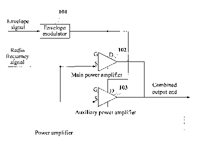
[0033] FIG 1 is a schematic structural diagram of a power amplifier
according to an embodiment of
6
CA 02956847 2017-01-31
. 52663-279
the present invention.
[0034] As shown in FIG 1, the power amplifier provided in this
embodiment of the present
invention includes an envelope modulator 101, a main power amplifier 102, and
an auxiliary power
amplifier 103.
[0035] The envelope modulator 101 is connected separately to a drain
electrode (D end) of the
main power amplifier 102 and a drain electrode of the power amplifier 103, and
is configured to obtain
a corresponding envelope voltage according to an envelope signal, and
separately output the envelope
voltage to the main power amplifier 102 and the auxiliary power amplifier 103.
[0036] The envelope signal is a signal that may be used to track an
operating voltage of the main
power amplifier 102, that is, when an amplitude of the envelope signal is
greater than a threshold, the
envelope modulator 101 generates an envelope voltage that may vary with an
amplitude size of the
envelope signal, to replace a fixed voltage to supply power separately to the
main power amplifier and
the auxiliary power amplifier. An operating voltage of the power amplifier
varies with the envelope
signal, so that the main power amplifier may be always in a near-saturation
operating state.
[0037] The envelope signal may be obtained after an original envelope
signal of a radio frequency
signal waiting for signal amplification is processed by using a function,
where the function converting
the original envelope signal into the envelope signal may be preset according
to a requirement such as
the amplitude and a phase of the output envelope signal. For example, the
function may be a linear
function, a quadratic function, a cubic function, or the like, which is not
limited in the present
invention. Optionally, the envelope signal may be generated by an RRU, or the
like, and is input into
the envelope modulator 101.
[0038] Optionally, the envelope modulator 101 may determine an
amplitude of the foregoing
envelope voltage according to a modulator control signal. A parameter such as
a type, a phase, or an
amplitude of the modulator control signal may be determined according to
performance of an amplifier
and may be adjusted according to an operating condition of the amplifier,
which is not limited in this
embodiment of the present invention. A digital signal may be used as the
modulator control signal.
[0039] Optionally, the foregoing modulator control signal may be
generated by an RRU, or the like,
and is input into the envelope modulator 101, which is not limited in this
embodiment of the present
invention.
[0040] The radio frequency signal to be amplified may be obtained by
converting a baseband data
signal. For a specific conversion process, reference may be made to the prior
art, and details are not
described herein. For example, in a distributed base station, a radio
frequency signal to be amplified
7
CA 02956847 2017-01-31
52663-279
may be generated after a baseband data signal is processed by using an
intermediate frequency module
and a transceiver module of an RRU, and transmitted separately to the main
power amplifier 102 and
the auxiliary power amplifier 103 in the power amplifier provided in this
embodiment of the present
invention.
[0041] Optionally, the envelope modulator 101 may compare the amplitude of
the envelope signal
with a signal threshold, and when the amplitude of the envelope signal is less
than the signal threshold,
the envelope voltage is set to a fixed voltage, where a value of the fixed
voltage may be determined and
adjusted according to the foregoing modulator control signal; or when the
amplitude of the envelope
signal is greater than the signal threshold, the envelope voltage is set to a
varying voltage, where the
varying voltage varies with the amplitude of the envelope signal. When the
envelope signal reaches a
maximum value allowed by the power amplifier, the envelope voltage also has a
corresponding
maximum voltage value.
[0042] The foregoing signal threshold may be predetermined, within an
operating voltage range
allowed by the amplifier, according to a requirement, and is adjusted
according to an operating
condition of a system, which is not limited in this embodiment of the present
invention.
[0043] The main power amplifier 102 is connected to the envelope
modulator 101 and is
configured to, in an operating state, use the foregoing envelope voltage
received from the envelope
modulator 101 as an operating voltage, and perform amplification processing on
a signal input from a
source electrode (S end).
[0044] The auxiliary power amplifier 103 is parallelly connected to the
main power amplifier 102,
is connected to the envelope modulator 101, and is configured to, in an
operating state, use the
foregoing envelope voltage received from the envelope modulator 101 as an
operating voltage, and
perform amplification processing on a signal input from a source electrode.
[0045] It may be understood that the signals input from the source
electrodes of the main power
amplifier 102 and the auxiliary power amplifier 103 may be a same radio
frequency signal, or may also
be signals that can represent a same radio frequency signal after being
overlapped.
[0046] Optionally, when the envelope signal is less than a preset
threshold, a same fixed voltage is
input into the main power amplifier 102 and the auxiliary power amplifier 103
as an operating voltage.
In this case, the power amplifier provided in this embodiment of the present
invention is equivalent to a
standard Doherty amplifier, and in this operating mode, the power amplifier
may implement power
amplification of a radio frequency signal with a wide bandwidth, of modulation
signals. When the
envelope signal is greater than the preset threshold, a same varying voltage
that varies with the
8
CA 02956847 2017-01-31
52663-279
amplitude of the envelope signal is input into the main power amplifier 102
and the auxiliary power
amplifier 103 as an operating voltage. In this case, the power amplifier is a
Doherty amplifier using
envelope tracking, that is, the power amplifier operates in a cooperative
state of the envelope tracking
and the Doherty amplifier, and in this operating mode, the power amplifier has
a good amplification
effect for a modulation signal of high power and of a high peak-to-average
ratio.
[0047] Specifically, the envelope modulator 101 is connected separately
to the drain electrodes of
the main power amplifier 102 and the auxiliary power amplifier 103. The
envelope voltage obtained by
being processed by the envelope modulator 101 is input separately from the
drain electrodes of the
main power amplifier 102 and the auxiliary power amplifier 103, and is used as
the operating voltage
of the drain electrodes, to supply power for the main power amplifier 102 and
the auxiliary power
amplifier 103.
[0048] It may be understood that under control of a gate voltage,
regardless of whether the
operating voltages of the drain electrodes are fixed voltages or are varying
voltages, the main power
amplifier 102 is always biased in an AB-type operating state, and the
auxiliary power amplifier is
always biased in a C-type operating state.
[0049] Optionally, as another embodiment of the present invention, as
shown in FIG 2, an envelope
modulator 101 may further be connected separately to a gate electrode (G end)
of a main power
amplifier 102 and a gate electrode (G end) of an auxiliary power amplifier
103, and outputs an
envelope voltage separately to the gate electrodes of the main power amplifier
102 and the auxiliary
power amplifier 103, so as to assist in controlling, by using the envelope
voltage as a gate voltage,
operating states of the main power amplifier 102 and the auxiliary power
amplifier 103, thereby further
adjusting a power amplification gain, and improving power amplification
performance.
[0050] In an actual implementation, the envelope modulator 101 may be a
unit circuit that includes
circuit components known in the prior art, where composition of a specific
circuit of the envelope
modulator is not limited in this embodiment of the present invention.
[0051] Optionally, as shown in FIG 2, as another embodiment of the
present invention, the power
amplifier may further include an upconverter 105, connected separately to a
main power amplifier 102
and an auxiliary power amplifier 103, and configured to convert a radio
frequency signal to a same
operating frequency range as that of the main power amplifier 102 and that of
the auxiliary power
amplifier 103.
[0052] Optionally, as shown in FIG 2, the power amplifier may further
include a power divider
106, connected separately to the upconverter 105, the main power amplifier
102, and the auxiliary
9
CA 02956847 2017-01-31
52663-279
power amplifier 103, and configured to divide a radio frequency signal into
two signals having a same
or different energy, and output the two signals separately to the main power
amplifier 102 and the
auxiliary power amplifier 103 for signal amplification.
[0053] Optionally, as another embodiment of the present invention, the
power amplifier may
include an envelope modulator 101, a main power amplifier 102, an auxiliary
power amplifier 103, and
a power divider 106, where the power divider 106 directly receives a radio
frequency signal, divides
the radio frequency signal and then outputs signals obtained after division
separately to the main power
amplifier 102 and the auxiliary power amplifier 103.
[0054] Optionally, as shown in FIG 2, an output end of the main power
amplifier 102 and an output
.. end of the auxiliary power amplifier 103 may be connected to an impedance
transformation network
104, and a radio frequency signal after signal amplification reaches, after
being processed by the
impedance transformation network 104, a combined output end of the power
amplifier. The impedance
transformation network 104 is configured to perform an impedance match between
the main power
amplifier 102 and the auxiliary power amplifier 103, that is, to provide a
phase difference between the
two. The impedance transformation network may include a microstrip impedance
transformation
network, a bridge impedance transformation network, or any other impedance
transformation network,
which is not limited in this embodiment of the present invention.
[0055] Optionally, in another embodiment of the present invention, as
shown in FIG 3, a power
amplifier includes an envelope modulator 101, a main power amplifier 102, an
auxiliary power
amplifier 103, an upconverter 105, and a power divider 106, where the
upconverter 105 and the power
divider 106 are optional components. The power amplifier may further include:
three one-fourth
wavelength (X/4) transmission lines 104', where one is disposed between source
electrodes, that is,
signal input ends of the main power amplifier 102 and the auxiliary power
amplifier 103, one is
disposed between signal output ends of the main power amplifier 102 and the
auxiliary power amplifier
.. 103, and another one is disposed at a combined output end of the main power
amplifier 102 and the
auxiliary power amplifier 103. The X/4 transmission line 104' has a function
similar to that of an
impedance transformation network 104, and can provide a phase difference
between the main power
amplifier 102 and the auxiliary power amplifier 103.
[0056] In an actual implementation, when a Doherty power amplifier part
in the power amplifier
provided in this embodiment of the present invention is designed, any of the
foregoing various
connecting manners may be used, so that a composition form of the power
amplifier provided in the
present invention is flexible, and may be selected according to a performance
requirement of the
CA 02956847 2017-01-31
52663-279
system.
[0057] In the actual implementation, the main power amplifier 102 and
the auxiliary power
amplifier 103 may include one or more transistors or other similar circuit
components. A person of
ordinary skill in the art may realize that the main power amplifier 102 and
the auxiliary power amplifier
103 may be implemented by using any other semiconductor technologies known in
the prior art, which
is not limited in this embodiment of the present invention.
[0058] Optionally, as shown in FIG 4, in another embodiment of the
present invention, a power
amplifier includes an envelope modulator 101, a main power amplifier 102, an
auxiliary power
amplifier 103, an impedance transformation network 104, and upconverters 105.
The impedance
transformation network 104 may be replaced with three X,/4 transmission lines.
For details, reference
may be made to description of the embodiment shown in FIG 3.
[0059] The power amplifier may further include two independent signal
transmission lines
separately corresponding to the main power amplifier 102 and the auxiliary
power amplifier 103.
Specifically, a radio frequency signal may be divided in advance into a first
radio frequency signal and
a second radio frequency signal, which are output separately to the main power
amplifier 102 and the
auxiliary power amplifier 103 by using the two independent signal transmission
lines, and then
combined and output after signal amplification. An upconverter 105 may be
disposed in each signal
transmission line, which is referred to as a first upconverter or a second
upconverter. Specifically, the
first radio frequency signal may be output to the main power amplifier 102
after being converted by the
first upconverter, and the second radio frequency signal may be output to the
auxiliary power amplifier
103 after being converted by the second upconverter. The first radio frequency
signal and the second
radio frequency signal are relevant signals, represent the same baseband data
signal, and have a same
time delay. After conversion, phases and/or amplitudes of the two signals may
be different, and the
amplitudes and the phases may be controlled separately. A person skilled in
the art may select a suitable
signal dividing manner according to a design requirement of a system, which is
not limited in this
embodiment of the present invention.
[0060] By using the power amplifier provided in this embodiment of the
present invention, a main
power amplifier and an auxiliary power amplifier both use an envelope voltage
output by an envelope
modulator as operating voltages, and when an envelope signal is less than a
preset threshold, the
envelope voltage is a fixed voltage, so that the power amplifier operates in
an ordinary Doherty
amplifier mode; or when the envelope signal is greater than a preset
threshold, the envelope voltage
varies with an amplitude of the envelope signal, so that the power amplifier
operates in an envelope
11
CA 02956847 2017-01-31
52663-279
tracking Doherty amplifier mode. Because the operating voltages of the main
power amplifier and the
auxiliary power amplifier may be adjusted simultaneously, symmetry of the
power amplifier is
improved, and there is a low probability that an efficiency loss occurs. By
using an efficiency
advantage of a Doherty amplifier under power back-off, and in combination with
an envelope tracking
technology, saturation power of power amplification is improved, thereby
enhancing efficiency of the
power amplifier. Particularly, in an operating state in which a signal of high
power and of a high
peak-to-average ratio is amplified, high efficiency may be reached.
[0061] FIG 5 is a schematic structural diagram of another power
amplifier according to an
embodiment of the present invention.
[0062] As shown in FIG 5, the power amplifier provided in this embodiment
of the present
invention includes an envelope modulator 201, a main power amplifier 202, and
A (where A is greater
than or equal to 2, and A is an integer) auxiliary power amplifiers 203.
[0063] The power amplifier may further include an impedance
transformation network 204, an
upconverter 205, and a power divider 206. It may be understood that optional
functional modules listed
in embodiments shown in FIG 1 to FIG 4 are also applicable to a structure of
the embodiment shown
in FIG 5. For example, the impedance transformation network 204 may be
replaced with a plurality of
X/4 transmission lines, including that: a A14 transmission line is disposed
separately between a source
electrode of the main power amplifier 202 and a source electrode of each
auxiliary power amplifier
203, a 2/4 transmission line is disposed separately between a signal output
end of the main power
amplifier 202 and a signal output end of each auxiliary power amplifier 203,
and a 214 transmission line
is disposed at a combined output end of the main power amplifier 202 and the A
auxiliary power
amplifiers 203; and the power divider 206 may be replaced with two independent
signal transmission
lines separately corresponding to the main power amplifier 202 and the A
auxiliary power amplifiers
203, where the main power amplifier 202 receives a radio frequency signal, and
the A auxiliary power
amplifiers 203 receive the other radio frequency signal. A person skilled in
the art may select to use
according to an actual need, which is not limited in this embodiment of the
present invention. The
structure shown in FIG 5 is only an optional implementation solution.
[0064] A drain electrode (D end) of the main power amplifier 202 and
drain electrodes (D ends) of
the A auxiliary power amplifiers 203 are connected separately to the envelope
modulator 201, and the
main power amplifier 202 and the A auxiliary power amplifiers 203 receive a
same envelope voltage
separately from the envelope modulator 201 as operating voltages, for
performing amplification
processing on a radio frequency signal.
12
CA 02956847 2017-01-31
52663-279
[0065] In the power amplifier, the envelope modulator 201 may further be
connected separately to a
gate electrode (G end) of the main power amplifier 202 and gate electrodes (G
ends) of the A auxiliary
power amplifiers 203, so as to assist in controlling, by using the envelope
voltage output by the
envelope modulator 201 as a gate voltage, operating states of the main power
amplifier and the
auxiliary power amplifiers, thereby further adjusting a power amplification
gain, and improving power
amplification performance.
[0066] It may be understood that a quantity of the auxiliary power
amplifiers may be determined
according to a system requirement, that is, a Doherty amplifier part in the
power amplifier provided in
this embodiment of the present invention may be a multi-channel Doherty power
amplifier shown in
FIG 3, which may include two or more auxiliary power amplifiers.
[0067] During an actual application, an implementation manner of the
Doherty amplifier part in the
power amplifier provided in this embodiment of the present invention is not
limited, and in addition to
a structure of the multi-channel Doherty amplifier, a structure inverse to
that of the Doherty amplifier
may be designed, which is not limited in this embodiment of the present
invention.
[0068] For description brevity, for description about a detailed structure,
and connection
relationships between and functions of modules of the power amplifier provided
in the embodiment
shown in FIG 5, reference may be made to related content of the embodiments
shown in FIG 1 to FIG
4, which is not described herein in detail.
[0069] By using the power amplifier provided in the embodiment shown in
FIG 5, because the
quantity of the auxiliary power amplifiers increases, larger output power may
be generated, and device
performance is further improved.
[0070] FIG 6 is a schematic structural diagram of still another power
amplifier according to an
embodiment of the present invention.
[0071] As shown in FIG 6, the power amplifier provided in this
embodiment of the present
invention includes: a first envelope modulator 3011, a second envelope
modulator 3012, a main power
amplifier 302, and B (where B is greater than or equal to 1, and B is an
integer) auxiliary power
amplifiers 303, where the first envelope modulator 3011 is connected to a
drain electrode (D end) of the
main power amplifier 302, the second envelope modulator 3012 is connected
separately to drain
electrodes of the B auxiliary power amplifiers 303, and the main power
amplifier 302 is parallelly
connected to the B auxiliary power amplifiers 303.
[0072] In the power amplifier, the first envelope modulator 3011 may
further be connected to a gate
electrode (G end) of the main power amplifier 302 and the second envelope
modulator 3012 may
13
CA 02956847 2017-01-31
52663-279
=
further be connected separately to gate electrodes of the B auxiliary power
amplifiers 302, so as to
assist in controlling, by using envelope voltages output by the envelope
modulators as gate voltages,
operating states of the main power amplifier and the auxiliary power
amplifiers, thereby further
adjusting a power amplification gain, and improving power amplification
performance.
[0073] The power amplifier may further include an impedance transformation
network 304, an
upconverter 305, and a power divider 306, and connection relationships are
shown in FIG 6. It may be
understood that optional functional modules listed in embodiments shown in FIG
1 to FIG 4 are also
applicable to a structure of the embodiment shown in FIG 6. For example, the
impedance
transformation network 304 may be replaced with a plurality of X/4
transmission lines, including that: a
k/4 transmission line is disposed separately between a source electrode of the
main power amplifier 302
and a source electrode of each auxiliary power amplifier 303, a k/4
transmission line is disposed
separately between a signal output end of the main power amplifier 302 and a
signal output end of each
auxiliary power amplifier 303, and a 214 transmission line is disposed at a
combined output end of the
main power amplifier 302 and the B auxiliary power amplifiers 303; and the
power divider 306 may be
replaced with two independent signal transmission lines separately
corresponding to the main power
amplifier 302 and the B auxiliary power amplifiers 303. A person skilled in
the art may select to use
according to an actual need, which is not limited in this embodiment of the
present invention. The
structure shown in FIG 6 is only an optional implementation solution.
[0074] The first envelope modulator 3011 is configured to receive a
first envelope signal, obtain a
first envelope voltage according to the first envelope signal, and output the
first envelope voltage to the
main power amplifier 302; and the main power amplifier 302 performs, by using
the first envelope
voltage as an operating voltage, amplification processing on a signal input
from a source electrode (S
end).
[0075] The second envelope modulator 3012 is configured to receive a
second envelope signal,
obtain a second envelope voltage according to the second envelope signal, and
output the second
envelope voltage to the B auxiliary power amplifiers 303; and the B auxiliary
power amplifiers
perform, by using the second envelope voltage as operating voltages,
amplification processing on a
signal input from source electrodes.
[0076] Optionally, the first envelope signal and the second envelope
signal may be generated by an
RRU, or the like, and are respectively input into the first envelope modulator
3011 and the second
envelope modulator 3012.
[0077] It may be understood that the signals input from the source
electrodes of the main power
14
CA 02956847 2017-01-31
52663-279
amplifier 302 and the auxiliary power amplifiers 303 may be a same radio
frequency signal to be
amplified, or signals that can represent a same radio frequency signal to be
amplified after being
overlapped.
[0078] Optionally, the first envelope modulator 3011 may process, under
control of a first
modulator control signal, the first envelope signal to obtain the first
envelope voltage, and the second
envelope modulator 3012 may process, under control of a second modulator
control signal, the second
envelope signal to obtain the second envelope voltage.
[0079] Optionally, by adjusting the first modulator control signal and
the second modulator control
signal, a proportional relationship between the first envelope voltage and the
second envelope voltage
may correspond to a ratio of an output power of the main power amplifier 302
to those of the auxiliary
power amplifiers 303. Specifically, according to an expected ratio of an
operating voltage of the main
power amplifier to those of the auxiliary power amplifiers, a suitable first
modulator control signal and
second modulator control signal are set, so that a ratio of a first envelope
voltage output by the first
envelope modulator 3011 and supplied for the main power amplifier 302 to a
second envelope voltage
output by the second envelope modulator 3012 and supplied for the auxiliary
power amplifiers 303 may
be controlled to be equal or corresponding to the foregoing output power
ratio, to ensure that an ratio of
an operating voltage of the main power amplifier to those of the auxiliary
power amplifiers maintains
constant, thereby amplifying radio frequency signals synchronously, and
keeping symmetry of the
amplifier.
[0080] Optionally, the first modulator control signal and the second
modulator control signal may
be generated by an RRU, or the like.
[0081] It should be noted that the first modulator control signal and
the second modulator control
signal may be of a same type or of different types, and may have relevant or
irrelevant parameters such
as amplitudes and phases. It only needs to ensure that the envelope voltages
output after being
processed by the envelope modulators satisfy a proportional relationship,
which is not limited in this
embodiment of the present invention.
[0082] The foregoing output power ratio is determined by performance of
power tubes selected as
the main power amplifier and the auxiliary power amplifier, for example, if
output power of a power
tube used as the main power amplifier is 100 W (W), and output power of a
power tube used as the
auxiliary power amplifier is 200 W (W), the output power ratio is 1:2, and the
first modulator control
signal and the second modulator control signal are determined as required by
the output power ratio, so
that a ratio of the first envelope voltage obtained after the first envelope
signal is processed by the first
CA 02956847 2017-01-31
52663-279
envelope modulator to the second envelope voltage obtained after the second
envelope signal is
processed by the second envelope modulator is also equal or approximate to
1:2.
[0083] Optionally, the first envelope modulator 3011 may process,
according to a first signal
threshold, the foregoing first envelope signal to obtain a fixed voltage or a
varying voltage that varies
with an amplitude of the foregoing first envelope signal; and the second
envelope modulator 3012 may
process, according to a second signal threshold, the foregoing second envelope
signal to obtain a fixed
voltage or a varying voltage that varies with an amplitude of the foregoing
second envelope signal. The
first preset threshold and the second preset threshold may be set and adjusted
independently, and may
be set to a same threshold or different thresholds according to a performance
requirement of the
amplifier, which is not limited in this embodiment of the present invention.
[0084] Optionally, the first envelope signal and the second envelope
signal may be relevant signals
obtained after an original envelope signal of a same radio frequency signal is
processed by using
different functions, and the first envelope voltage obtained after being
processed according to the first
envelope signal and the second envelope voltage obtained after being processed
according to the
second envelope signal are relevant envelope voltages.
[0085] Optionally, the first envelope signal and the second envelope
signal may also be a same
envelope signal obtained after an original envelope signal of a radio
frequency signal is processed by
using a preset function, and are respectively output to the first envelope
modulator 3011 and the second
envelope modulator 3012. Because signal thresholds may be set independently
for the first envelope
modulator 3011 and the second envelope modulator 3012, the first envelope
voltage and the second
envelope voltage obtained after being processing may be a same envelope
voltage or relevant envelope
voltages. Regardless of whether the same or relevant envelope voltages are
obtained after being
processing, under actions of the first modulator control signal and the second
modulator control signal,
the first envelope voltage and the second envelope voltage may always maintain
a fixed proportional
relationship.
[0086] For description brevity, for description about a detailed
structure, and connection
relationships between and functions of modules of the power amplifier provided
in the embodiment
shown in FIG 6, reference may be made to related content of the embodiments
shown in other
embodiments of the present invention, which is not described herein in detail.
[0087] By using the power amplifier provided in the embodiment in FIG 6,
envelope channels of
the main power amplifier and the auxiliary power amplifiers are configured
independently, the main
power amplifier and the auxiliary power amplifiers may set and adjust the
envelope voltages separately,
16
CA 02956847 2017-01-31
' 52663-279
and meanwhile the envelope voltage ratio matches the output power ratio of the
amplifier, which has
good flexibility, and may further improve performance of the amplifier.
[0088] It may be known from description of the forgoing embodiment
that, quantities of the
envelope modulators and the auxiliary power amplifiers in the power amplifier
provided in this
embodiment of the present invention may be determined according to a system
requirement, and the
connection relationships between the modules also vary correspondingly, which
is not limited in this
embodiment of the present invention. For example, C (where C is greater than
or equal to 2) auxiliary
power amplifiers and C+1 (where C is greater than or equal to 2) envelope
modulators may be
disposed, where one of the C+1 envelope modulators is connected to the main
power amplifier, and the
remaining C envelope modulators are respectively connected to the C auxiliary
power amplifiers, that
is, the envelope modulators are in a one-to-one correspondence to the
auxiliary power amplifiers, and
each envelope modulator may be controlled independently. For another example,
similar to the
embodiment shown in FIG 5, C (where C is greater than or equal to 2) auxiliary
power amplifiers and
two envelope modulators may be disposed, where one envelope modulator is
connected to the main
power amplifier; and the other envelope modulator is connected to the C
auxiliary power amplifiers
simultaneously, for providing an operating voltage for the C auxiliary power
amplifiers; or one
envelope modulator is connected to the main power amplifier and some of the
auxiliary power
amplifiers, and the other envelope modulator is connected to the remaining
auxiliary power amplifiers.
That is, it only needs to ensure that operating voltages of a main power
amplifier and auxiliary power
.. amplifiers are all provided by envelope voltages output by envelope
modulators, and a ratio of an
operating voltage of the main power amplifier to those of the auxiliary power
amplifiers corresponds to
an output power ratio.
[0089] As shown in FIG 7, an embodiment of the present invention
further provides a radio remote
unit, including a power amplifier 401. The power amplifier 401 may be the
power amplifier shown in
any embodiment of FIG. 1 to FIG 6 or an apparatus having a same function. For
description about an
internal structure and function of the power amplifier 401, reference may be
made to other
embodiments of the present invention, which is not described herein in detail.
[0090] The RRU may further include a processor 402, configured to
extract an original envelope
signal of a radio frequency signal to be amplified, process the original
envelope signal by using a preset
.. function, to obtain an envelope signal, and output the envelope signal to
the power amplifier 401. The
power amplifier 401 processes the envelope signal to obtain an envelope
voltage, which is used as an
operating voltage of the power amplifier.
17
CA 02956847 2017-01-31
52663-279
[0091] Optionally, the processor 402 may further be configured to
generate a modulator control
signal and output the modulator control signal to the power amplifier 402,
where the modulator control
signal may be used to control an amplitude of the foregoing envelope voltage.
[0092] Optionally, when the power amplifier 401 includes a first
envelope modulator connected to
a main power amplifier, and a second envelope modulator connected to an
auxiliary power amplifier,
the processor 402 may be configured to generate a first modulator control
signal corresponding to the
first envelope modulator, and a second modulator control signal corresponding
to the second envelope
modulator. For details, reference may be made to description of the embodiment
shown in FIG 6,
which is not described herein in detail.
[0093] The processor 402 may communicate with the power amplifier 401
directly or indirectly.
[0094] It may be understood that the foregoing processor 402 may be
disposed independently, or a
function thereof may also be integrated in an existing functional module, for
example, an intermediate
frequency module or a transceiver module, of the RRU, which is not limited in
this embodiment of the
present invention. During an actual implementation, the function of the
processor 402 may be
integrated on a baseband chip.
[0095] The RRU may further include a communications interface 403,
configured to communicate
with another apparatus, for example, a baseband unit (BBU) in a base station
directly or indirectly.
[0096] Optionally, the communications interface 403 may be a common
public radio interface
(CPRI, Common Public Radio Interface), an open base station architecture
initiative (OBASI)
interface, or the like.
[0097] Connection manners of the power amplifier 401, the processor
402, and the communications
interface 403 are not limited. As shown in FIG 7, the power amplifier 401, the
processor 402, and the
communications interface 403 may be connected by using a communications bus
404 for signal
transmission. .
[0098] For clear and brief description, this embodiment of the present
invention uses a power
amplifier that is disposed in an RRU for description. A person skilled in the
art may understand that the
power amplifier may also be disposed in another similar radio frequency
functional module, which is
not limited in this embodiment of the present invention.
[0099] As shown in FIG 8, an embodiment of the present invention further
provides a base station,
including a radio remote unit 501 and a baseband unit 502. The radio remote
unit 501 may be the radio
remote unit shown in the embodiment of FIG 7 or a device having a same
function, and the radio
remote unit 501 and the baseband unit 502 may communicate directly or
indirectly.
18
CA 02956847 2017-01-31
52663-279
[0100] By using the radio remote unit or the base station provided in
this embodiment of the
present invention, a main power amplifier and an auxiliary power amplifier
that are used in a power
amplification part both use an envelope voltage output by an envelope
modulator as operating voltages,
and when an envelope signal is less than a preset threshold, the envelope
voltage is a fixed voltage, so
that the power amplifier operates in an ordinary Doherty amplifier mode; or
when the envelope signal
is greater than a preset threshold, the envelope voltage varies with an
amplitude of the envelope signal,
so that the power amplifier operates in an envelope tracking Doherty amplifier
mode. Because the
operating voltages of the main power amplifier and the auxiliary power
amplifier may be adjusted
simultaneously, symmetry of the power amplifier is improved, and there is a
low probability that an
efficiency loss occurs. By using an efficiency advantage of a Doherty
amplifier under power back-off,
and in combination with an envelope tracking technology, saturation power of
power amplification is
improved, thereby enhancing efficiency of the power amplifier. Particularly,
in an operating state in
which a signal of high power and of a high peak-to-average ratio is amplified,
high efficiency may be
reached.
[0101] It may be understood that various proper modifications may be made
by a person of
ordinary skill in the art to quantities of envelope modulators and auxiliary
power amplifiers of a power
amplifier and to corresponding connection relationships according to
description of the embodiments of
the present invention, without creative efforts, and shall fall within the
protection scope of the present
invention.
[0102] In the several embodiments provided in the present application, it
should be understood that
the disclosed device and method may be implemented in other manners. For
example, the described
apparatus embodiment is merely exemplary. For example, the module division is
merely logical
function division and may be other division in actual implementation. For
example, a plurality of
modules or components may be combined or integrated into another device, or
some features may be
ignored or not performed.
[0103] In addition, functional modules in the embodiments of the present
invention may be
integrated into one processing module, or each of the modules may exist alone
physically, or two or
more modules are integrated into one module.
101041 A person of ordinary skill in the art may understand that all or
some of the steps of the
embodiments may be implemented by hardware or a program instructing related
hardware. The
program may be stored in a computer-readable storage medium. The storage
medium may include: a
read-only memory, a magnetic disk, or an optical disc.
19
,
CA 02956847 2017-01-31
52663-279
[0105] Finally, it should be noted that the foregoing embodiments are
merely intended for
describing the technical solutions of the present invention, but not for
limiting the present invention.
Although the present invention is described in detail with reference to the
foregoing embodiments,
persons of ordinary skill in the art should understand that they may still
make modifications to the
technical solutions described in the foregoing embodiments or make equivalent
replacements to some
or all technical features thereof, without departing from the scope of the
technical solutions of the
embodiments of the present invention.