Note: Descriptions are shown in the official language in which they were submitted.
CA 02957254 2017-02-03
WO 2016/020848
PCT/IB2015/055934
1
A GLUELAM STRUCTURAL MEMBER AND A METHOD OF PRODUCING
SUCH A GLUELAM STRUCTURAL MEMBER
Technical Field
The present disclosure relates to a structural member, which may be
used as a beam, a joist, a stud, a pillar or the like. The disclosure also
relates
to a method of producing the structural member.
Background
Currently, glue-laminated beams ("gluelam") in Europe are mostly
produced according to DIN 1052:2008 (German standard) or DIN EN 14080:
2013-09 (harmonized European standard). The beams 1 (Fig. 1) are built up
with visually graded or machine graded boards 2, which are produced and
kiln-dried in sawmills in the traditional way.
The gluelam producer takes these boards as raw material, grades
them and produces the required lamellae by cutting out defects (e.g. knots)
and finger-jointing 3 the pieces together. After the finger-jointed lamellae 2
have been planed, glue is applied and the beam 1 is formed by gluing the
lamellae 2 together. The final steps may comprise planing the beam,
removing optical defects, packaging and loading it.
Hence, traditionally, timber is sawn into planks or lamellae according to
the scheme depicted in Fig. 1 of U55816015, which discloses alternative
methods of forming wood beams by laminating together a plurality of planks
or lamellae.
EP1277552A2 discloses a similar method of forming a wood beam by
cutting a round piece of timber into a plurality of strips having a
trapezoidal
cross section and laminating together the pieces thus formed into a beam.
US4122878 discloses a method of converting balsa wood of relatively
small diameter into panels.
There is still a need to provide improved use of the timber raw material,
as well as a need for beams having improved strength and/or reduced
variation in strength between different beams.
81799221
2
Summary
It is a general object of the present invention to provide an improved
structural member, such as a beam, a joist, a stud, a pillar or the like. A
particular
object includes the provision of a structural member which makes better use of
existing raw materials and which is stronger. Further objects include the
provision
of improved control of the production process of structural members, such that
properties of resulting members will present less variation.
According to some embodiments disclosed herein, there is provided a
structural member in the form of a gluelam beam having an elongate cross
section
presenting a horizontally oriented short side and a predetermined main bending
direction, which is perpendicular to the short side, comprising: a plurality
of glued-
together wood lamellae, each having a lamella cross section which is parallel
with
a cross section of the structural member and a longitudinal direction which is
parallel with a longitudinal direction of the structural member and with a
principal
grain direction of the wood lamellae, wherein the lamellae are formed as
radial
sections of a log, wherein the lamellae present cross sections which are
triangular
or trapezoidal and present a respective planar major base surface that is
formed
at a radially outer part of the log, wherein the planar major base surfaces
are
perpendicular to the main bending direction, and wherein the planar major base
surfaces are parallel to the short side of the cross section, wherein the
structural
member comprises at least two glued-together layers of lamellae that are
arranged such that the planar major base surfaces of a pair of immediately
adjacent lamellae face opposite directions, and, wherein a layer that is
positioned
closer, as seen in the main bending direction, to an outer face of the
structural
member presents a smaller number of annual rings than a layer that is
positioned
further away from the outer face.
According to a first aspect, there is provided a structural member, such as a
beam, a stud or a joist, presenting a predetermined main bending direction.
The
structural member comprises a plurality of glued-together wood lamellae, each
having a lamella cross section which is parallel with a cross section of the
structural member and a longitudinal direction which is parallel with a
longitudinal
direction of the structural member and with a principal grain direction of the
wood
Date Recue/Date Received 2021-08-06
81799221
2a
lamellae. The lamellae are formed as radial sections of a log and present
cross
sections which are triangular or trapezoidal and present a respective base
surface
that is formed at a radially outer part of the log. The lamellae are arranged
as at
least one layer in which base surfaces of a pair of immediately adjacent
lamellae
face opposite directions. The base surfaces are perpendicular to the bending
direction.
The term "trapezoid" is the American English equivalent of the British
English term "trapezium". The term "trapezoid is defined as a convex
quadrilateral
with one pair of parallel sides, referred to as "bases" and a pair of non-
parallel
legs.
The term "bending direction" can be replaced with "transversal load
direction", which is perhaps more relevant for the case where the structural
member is in the form of a beam which receives a transversal load over all or
part
thereof.
Date Recue/Date Received 2021-08-06
CA 02957254 2017-02-03
WO 2016/020848
PCT/IB2015/055934
3
The invention is thus based on the understanding that strength
properties (tensile as well as bending strength) increase radially from pith
to
bark. Hence, the youngest (i.e. most outside lying) wood is the most valuable
in terms of strength properties. While today's sawmilling technology results
in
-- most of the outside lying wood being converted into chips and not into sawn-
goods, the present invention provides for an enhanced use of the most
valuable wood, since the inventive concept will result in the forming of
pieces
of wood which will always include the outermost part of the log.
It is estimated that beams formed according to the present disclosure
can achieve about 10 % increase in strength properties given the same
amount of raw material used.
The lamellae may have the shape of an isosceles triangle and/or of an
isosceles trapezoid.
Although other cross sections are possible, including varying or
-- alternating cross sections, an isosceles trapezoid shape for all lamellae
would
appear to be the most practical one from a production perspective.
In the lamellae, an annual ring radius of curvature may decrease with
an increasing distance from the base surface.
Hence, the youngest portion of the wood will be present at the major
-- base surface and the age of the wood will increase gradually towards the
minor base surface or towards the triangle apex, as the case may be.
The structural member comprises at least two glued-together layers of
lamellae that are arranged such that base surfaces of a pair of immediately
adjacent lamellae face opposite directions.
Hence, the present disclosure provides a modular approach to the
design of structural members in that standardized building blocks may be
used to form a variety of structural members having different properties.
The layers may present different thickness as seen in a direction
perpendicular to the base surfaces.
A layer that is positioned closer, as seen in the bending direction, to an
outer face of the structural member presents a smaller number of annual
rings than a layer that is positioned further away from the outer face.
CA 02957254 2017-02-03
WO 2016/020848
PCT/IB2015/055934
4
In the layer having the smaller number of annual rings, those lamellae
whose base surfaces face the same direction and which constitute the
greatest part by volume of that layer, may have a greater average annual ring
radius of curvature than the lamellae of the layer that is positioned further
away from the outer face.
Hence, the outer layer will have higher strength.
The lamellae may be formed of pieces of wood that are radial sectors
of a log having their respective apex and arc portions cut away.
The lamellae may present a trapezoidal cross section, and the major
base surfaces of the lamellae may present less cut-off wood fibers per area
unit than the minor base surfaces of the lamellae.
Hence, the wood fibers at the major base surface will be intact to a
higher degree than the wood fibers at the minor base surface. This means
that the quality of the wood fibers having the greatest strength will be
preserved and maximum use will be made of the inherent strength of the raw
material.
At least one of the lamellae may be formed by at least two pieces of
wood, which are joined together short side to short side, preferably by means
of a finger joint.
According to a second aspect, there is provided a gluelam beam
comprising a structural member as described above, wherein the beam has
an elongate cross section presenting a horizontally oriented short side,
wherein the base surfaces are parallel to the short side.
According to a third aspect, there is provided use of a structural
member as described above as a beam, a joist, a stud, a pillar or a wall
element.
A beam in this regard may be a straight horizontal beam or a slanted
beam, i.e. a beam having an angle of 0 -90 relative to a horizontal
direction.
A beam may also be curved.
A wall element may be used to provide all or part of a wall. Typical wall
elements may have a height corresponding to a desired room height, typically
about 2.1 - 4 m, perhaps most likely in the range of 2.2 - 3 m. A width of
such
CA 02957254 2017-02-03
WO 2016/020848
PCT/IB2015/055934
a wall element may be e.g. from 0.6 m to 25 m, perhaps most likely 0.6- 15 m
or 0.6 ¨ 6 m.
According to a fourth aspect, there is provided a method of forming a
structural member, such as a beam, a stud or a joist, presenting a
5 predetermined main bending direction. The method comprises cutting a log
along a principal grain direction of the log, into a plurality of wood
lamellae
which are triangular or trapezoidal in cross section and present a respective
base surface that is formed at a radially outer part of the log. The method
further comprises arranging the lamellae as at least one layer in which base
surfaces of a pair of immediately adjacent lamellae face opposite directions,
and gluing together the lamellae along long sides thereof. The method also
comprises arranging the lamellae such that the base surfaces are
perpendicular to the bending direction.
In the method, the lamellae may be formed with an isosceles triangular
or an isosceles trapezoidal cross section.
The forming of the lamellae into trapezoid cross section may comprise
aligning a respective major base surface of the lamella to be formed with an
outermost surface of the log, such that less wood fibers per area unit are cut
off at the major base surface than at a minor base surface.
The method may comprise a drying step, wherein the lamellae are
dried, preferably kiln-dried, to a moisture content suitable for lamination.
The method may further comprise a planing step, wherein the lamellae
and/or the layers are planed to provide a sufficiently plane surface for
lamination.
The method may comprise cutting away a portion of the layer
comprising the base surfaces and gluing this portion to an opposing side of
the layer or to a part of another layer forming part of the structural member
and being parallel with the cut away portion.
According to yet another inventive concept, there is provided a building
component, such as a beam, a stud, a joist or a sheet, comprising a plurality
of glued-together wood lamellae, each having a lamella cross section which is
parallel with a cross section of the structural member and a longitudinal
direction which is parallel with a longitudinal direction of the structural
CA 02957254 2017-02-03
WO 2016/020848
PCT/IB2015/055934
6
member and with a principal grain direction of the wood lamellae. The
lamellae are formed as radial sections of a log and present cross sections
which are trapezoidal and present a respective base surface that is formed at
a radially outer part of the log. The lamellae are arranged as at least one
layer
in which base surfaces of a pair of immediately adjacent lamellae face
opposite directions. Major base surfaces of the lamellae present less cut-off
wood fibers per area unit than minor base surfaces of the lamellae.
Hence, the wood fibers at the major base surface will be intact to a
higher degree than the wood fibers at the minor base surface. This means
that the quality of the wood fibers having the greatest strength will be
preserved and maximum use will be made of the inherent strength of the raw
material.
This second inventive concept may be used with or without base
surfaces that are are perpendicular to a bending direction or transversal load
direction of the building component.
In the lamellae, an annual ring radius of curvature may decrease with
an increasing distance from the base surface.
Hence, the youngest portion of the wood will be present at the major
base surface and the age of the wood will increase gradually towards the
minor base surface or towards the triangle apex, as the case may be.
The building component may comprise at least two glued-together
layers of lamellae that are arranged such that base surfaces of a pair of
immediately adjacent lamellae face opposite directions.
Hence, the present disclosure provides a modular approach to the
design of building components in that standardized building blocks may be
used to form a variety of building components having different properties.
The layers may present different thickness as seen in a direction
perpendicular to the base surfaces.
A layer that is positioned closer, as seen in a bending direction or
transversal load direction, to an outer face of the building component
presents
a smaller number of annual rings than a layer that is positioned further away
from the outer face.
CA 02957254 2017-02-03
WO 2016/020848
PCT/IB2015/055934
7
In the layer having the smaller number of annual rings, those lamellae
whose base surfaces face the same direction and which constitute the
greatest part by volume of that layer, may have a greater average annual ring
radius of curvature than the lamellae of the layer that is positioned further
away from the outer face.
Hence, the outer layer will have higher strength.
The lamellae may be formed of pieces of wood that are radial sectors
of a log having their respective apex and arc portions cut away.According to a
second aspect of the second inventive concept, there is provided use of a
building component as described above as a beam, a joist, a stud, a pillar or
a wall element.
According to a third aspect of the second inventive concept, there is
provided a method of forming a building component, such as a beam, a stud,
a joist or a sheet, presenting a predetermined main bending direction. The
method comprises cutting a log along a principal grain direction of the log,
into a plurality of wood lamellae which are trapezoidal in cross section and
present a respective base surface that is formed at a radially outer part of
the
log. The method further comprises arranging the lamellae as at least one
layer in which base surfaces of a pair of immediately adjacent lamellae face
opposite directions, and gluing together the lamellae along long sides
thereof.
The forming of the lamellae into trapezoid cross section comprises aligning a
respective major base surface of the lamella to be formed with an outermost
surface of the log, such that less wood fibers per area unit are cut off at
the
major base surface than at a minor base surface.
Brief Description of the Drawinps
Fig. 1 schematically illustrates a prior art gluelam beam.
Fig. 2 schematically illustrates a gluelam beam according to the
present inventive concept.
Figs 3a-3c schematically illustrate different embodiments of gluelam
beams according to the present inventive concept.
Fig. 4 schematically illustrates a part of a layer of a gluelam beam
according to the present inventive concept.
CA 02957254 2017-02-03
WO 2016/020848
PCT/IB2015/055934
8
Fig 5a-5c schematically illustrate different embodiments of gluelam
beams according to the present inventive concept.
Figs 6a-6j schematically illustrate steps which may be used in the
production of a gluelam beam according to the present inventive concept.
Detailed Description
In the present disclosure, the inventive concept will be illustrated with
reference to a beam 10, which presents a cross section and a longitudinal
direction L, and which will typically be intended to receive and support one
or
more loads, which may be distributed more or less evenly over all or parts of
the longitudinal direction of the beam 10. In most practical situations, the
force will be vertical, and so the vertical bending of the beam 10 will be the
most relevant.
The cross section may, as illustrated in Fig. 2, be substantially
rectangular with short sides of the rectangle being substantially horizontal.
For simplicity, the surfaces defined by the short sides will be referred to as
"upper side" and "lower side". The long sides of the rectangle define side
surfaces of the beam. Such a beam may be arranged substantially
horizontally, or it may extend more or less at an angle to the horizontal
direction, for example to support a staircase, a roof, etc. As yet another
example, the beam may be curved, for example to support a curved roof.
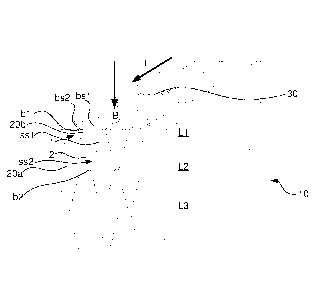
Fig. 2 thus schematically illustrates a beam 10, which is formed of
three layers Li, L2, L3 of lamellae 20a, 20b. A bending direction B is
illustrated as the direction in which a typical transversal load will act upon
the
beam 10. Hence, for a beam which is subjected to a transversal load (e.g. a
perpendicularly oriented load), the bending direction B will coincide with the
transversal load direction.
The lamellae 20a, 20b present a respective cross section, which, in the
illustrated example, has the shape substantially of an isosceles trapezoid,
which is the result of the lamellae being formed by radially sectioning a log
or
a piece of timber.
Each lamella cross section will thus present a pair of bases b1, b2
defining respective base surfaces bs1, bs2 of the lamellae 20a, 20b and a
CA 02957254 2017-02-03
WO 2016/020848
PCT/IB2015/055934
9
pair of legs 11, 12 defining respective side surfaces ss1, ss2 of the lamella
20a,
20b. The base surfaces bs1, bs2 comprise a major base surface bs1 and a
minor base surface bs2. In each lamella, the major base surface bs1 is
formed at an outer portion of the log, closer to the bark than to the pith and
the minor base surface bs2 is formed at an inner portion of the log, closer to
the pith. It is preferable to provide the longitudinal sides of the major base
surface bs1 to coincide with the lateral surface of the useful part of the log
(i.e. the outermost part of the log when the bark has been cut away.
The lamellae 20a, 20b in each layer L1, L2, L3 are arranged side
surface ss1 to side surface ss2 with major base surfaces bs1 of immediately
adjacent lamellae 20a, 20b facing opposite directions.
Hence, in e.g. the uppermost layer L1 of Fig. 2, the upwardly facing
surface of the beam 10, will be formed by major base surfaces bs1 and minor
base surfaces bs2, which are presented alternating as seen in a width
-- direction of the beam 10. The upwardly and/or downwardly facing surface of
the beam may thus consist essentially to at least 50 %, preferably at least 60
%, at least 70 %, at least 80 %, at least 90 %, at least 95 % or at least 98
%,
of the major base surfaces bs1.
Fig. 3a schematically illustrates the simplest form of beam or joist that
can be formed according to the present inventive concept, with a single layer
of lamellae 20a, 20b which are laminated side by side with major base
surfaces bs1 facing alternating upwardly and downwardly, respectively.
Fig. 3b schematically illustrates a two-layer beam or joist that can be
formed according to the present inventive concept. This beam is thus formed
by two layers L1, L2 of lamellae, each of which are formed according to what
has been discussed above with reference to Figs 2 and 3a. The layers L1, L2
may be laminated together by gluing using conventional gluing technique. In
order to provide a longer structural member, it is possible to join together
layers L1, L2 of lamellae, e.g. by finger jointing, prior to the joining of
the
layers. L1, L2 to form the structural member.
Fig. 3c schematically illustrates a three-layer beam or joist that can be
formed according to the present inventive concept and similarly to that of
Fig.
3b. Hence, in this embodiment, the beam is formed of three layers L1, L2, L3
CA 02957254 2017-02-03
WO 2016/020848
PCT/IB2015/055934
of lamellae 20a, 20b, each layer being formed as disclosed above with
reference to Figs 2, 3a and 3b.
Each layer may typically have a thickness of about 5-20 cm, preferably
about 10-15 cm. A beam may be formed of as many layers as deemed
5 necessary. Current standard beams are available at a height of up to 1.2 m,
which would translate into a beam having 6-24 layers. Most likely, a beam of
that height would have 10-12 layers.
Fig. 4 schematically illustrates an enlarged view of the product
illustrated in Fig. 3a. As the uppermost and lowermost portions are formed
10 mainly by the outer wood, i.e. the younger wood, high strength zones HS
will
be provided at the uppermost and lowermost portions, while a middle strength
zone MS will be provided in between.
As can be seen in Fig. 4, the high strength zones HS will consist
mainly of wood from the outermost part of the log. This would then provide an
optimal beam, as it would be the strength of the uppermost and lowermost
portions that would be decisive for the bending strength of the beam.
Visually, the zones HS, MS can be distinguished by the radius of
curvature of the annual rings: the high strength zone HS will have a larger
proportion of annual rings having a greater radius of curvature than the
middle strength zone MS.
It is currently not possible to provide a clear limit on what is a high
strength zone and what is a middle strength zone. The decision on how to
define the zones may be based on experimental strength data and on due
regard to the cost of carrying out the "moving" operation.
In Fig. 5a, there is illustrated the case of Fig 3a, which will thus present
high strength zones at the upper and lower surfaces and a middle strength
zone in between. As is illustrated in Fig. 5a, a high strength zone HS may be
cut away, e.g. by sawing at the line Cl, and moved, as will be discussed
below.
In Fig. 5b, there is illustrated an embodiment wherein the beam or joist
is formed of four layers Li', L2', L3', L4': a pair of central layers L2', L3'
and a
pair of outermost layers L1', L4'. It is noted that the most centrally located
high strength zones HS of the central layers L2', L3' have been removed and
CA 02957254 2017-02-03
WO 2016/020848
PCT/IB2015/055934
11
laminated as outermost layers LI, L4'. Hence, effectively, the high strength
zones HS have been moved from a central location, where they are of less
use, to an outermost location, where better use will be made of their
strength.
These moved high strength zones will appear as outer layers that have
smaller thickness in the vertical direction than the central layers L2', L3'.
For
example, an average radius of curvature of the annual rings of the outer layer
Li', L4' lamellae may be greater than an average radius of curvature of the
central layers L2', L3'.
In Fig. 5c, there is illustrated a concept similar to that of Fig. 5b, but
with the beam or joist having three central middle strength zones MS and six
outer high strength zones HS, each outer layer being formed by "moving" the
centrally located high strength zones HS.
The description will now be directed towards a method for production
of the beam described above. As mentioned above, the number of layers to
be included in the beam is a matter of selection.
In Fig. 6a, there is illustrated a log 100 which has been longitudinally
cut in half and then radially sectioned into six segments 200, i.e. 12
segments
per log. Hence, each segment will have an apex angle of 30 . It is noted that
the number of segments into which each log will be sectioned may be
selected according to what is deemed appropriate. As a rule of thumb, the
greater the log diameter, the greater the number of segments. As another
example, 16 segments may be a suitable alternative, with the apex angle then
being 22.5 .
As examples, the starting material 100 may be a complete log or a
longitudinally cut log (as illustrated in Fig. 6a). The log may be regarded as
cylindrical (or semi-cylindrical) or as a truncated cone. In any event, the
starting material is radially sectioned, whereby a plurality of lamellae
blanks
200 are provided, the cross sections of which being in the form of a segment
of a circle.
When cutting the log, it is possible, and perhaps most practical, to form
the segments as isosceles trapezoids, as discussed above. However, it is
also possible to form the segments with other shapes, such as triangles,
CA 02957254 2017-02-03
WO 2016/020848
PCT/IB2015/055934
12
trapeziums or trapezoids, and to laminate such shapes together with an
ensuing planing step that will provide the final shape of a layer L1, L2, L3.
In Fig. 6b, there is illustrated a step in which the lamellae blanks 200
prepared in the preceding steps are laid up for drying. The drying process
may be any known type of drying process, e.g. a kiln-drying process and the
segments 200 may be dried to a moisture content that is suitable for the
lamination process that is to be used. There are many different techniques for
stacking lamellae, and many different techniques for drying, and no limitation
is intended in this regard.
In Fig. 6c, there is illustrated a step of identification and removal
(cutting away) of defects, such as knots. Processes for identifying and
managing defects in wood are known from e.g. US8408081B2 and
EP1355148. Parts of the lamellae blanks 200 that are deemed to have
insufficient strength may thus be identified and removed, e.g. by cutting away
the entire portion of the lamellae blank 200 that is affected by the defect.
In Fig 6d, there is illustrated a step of optimizing the lamellae. In this
step, lamellae blanks 200 are inspected and it is determined what will be the
optimal lamellae cross section for each lamellae blank. As is illustrated in
Fig.
6d, for lamellae blanks having the same original cross section it is possible
to
provide trapezoidal lamellae having, e.g. differently sized base surfaces
and/or different heights. The selection of what cross section to provide may
depend on factors such as wood type and quality, occurrence of defects, etc.
In Fig. 6e, there is illustrated a step of formatting lamellae 20 from the
lamellae blanks 200. In this step, the segment apex (i.e. the pith) and the
segment arc (i.e. the bark or the portion closest to the bark) may be cut away
to provide the desired triangular, trapezoidal or isosceles triangular or
trapezoidal shape. The formatting may also include planing and/or profiling of
the side edges and/or of the base surfaces. The formatting step is typically
carried out to achieve the shape determined in the optimization step.
It is noted that while in traditional sawmill practice; a log is treated as a
cylinder, wherein the smallest cross section of the log (typically the
uppermost
part of the log) will define the diameter of the cylinder.
CA 02957254 2017-02-03
WO 2016/020848
PCT/IB2015/055934
13
However, a log is actually a truncated cone with a taper of generally
about 5-7 mm/m tree height for Norway spruce in middle Europe. Other
tapers may apply to different wood species and/or in different locations.
Consequently, when using the traditional approach to formatting a lamella,
some of the most desirable wood, close to the bark, will be cut away while the
less desirable wood, closer to the pith, will be kept.
While the present inventive concept may very well be practiced using
this traditional approach, another approach will be described.
In the formatting step, the major base surface bs1 of the trapezoid will
be fitted as closely as possible along the outermost surface of the lamella
blank, as is illustrated in the far right part of Fig. 6e. Consequently, less
material will be cut away from the outermost portion of the log and more
material will be cut away from the portion closest to the pith.
In consequence, more of the desirable wood will be kept.
As wood fibers actually run parallel to the bark (i.e. the envelope of a
truncated cone) rather than along the length direction, of a log (which would
assume the log is a cylinder), the traditional method will lead to a lot of
wood
fibers being cut off at the major base surface bs1. Thus, for each area unit
of
the base surface, there will appear more cut off wood fibers at the major base
-- surface than at the minor base surface bs2.
However, with the herein described method, there will be less cut off
wood fibers per area unit at the major base surface than at the minor base
surface, thus resulting in more of the valuable wood being retained where it
is
needed. Phrased differently, the cutting of the most valuable part of the wood
-- will be more parallel to the fiber direction than in the traditional
method.
During the formatting step, the triangle or trapezoid may be taken at a
radial distance from the pith which optimizes the use of the lamellae blank
200, bearing in mind that the lamellae blank, as a consequence of being
formed from a starting material which is actually slightly frusto-conical in
shape, may have a cross section which varies over its length. At the end of
the formatting, a lamella in the form of a piece of wood having a prismatic
shape with a trapezoidal cross section and a longitudinal direction parallel
CA 02957254 2017-02-03
WO 2016/020848
PCT/IB2015/055934
14
with the fibers at the outermost part of the log from which it was formed has
been obtained.
In Fig. 6f, there is illustrated a step of providing an end portion of a
segment with a finger joint. Joining of wood lamellae is known per se and the
fingers may extend parallel with the base surfaces of the isosceles trapezoid,
parallel with a side surface of the trapezoid or parallel with a central
radius of
the lamella blank 200 from which the lamella is formed.
In Fig. 6g, there is illustrated an alternative way of providing the finger
joint. In this step, the fingers will extend along a side surface of the
trapezoid,
which may be advantageous for lamellae having a relatively high and narrow
cross section as the lamella would rest more stably on the support when the
fingers are being cut.
Other types of joints may be used, with a preference for a joint that
only involves the use of wood and glue.
In Fig. 6h, there is illustrated a finished lamella, which is formed of a
plurality of joined together segments. If the side edges have not previously
been planed or formatted, or additional planing or formatting is called for, a
side edge planing step may be provided at this point.
In a non-illustrated step, the finished lamella are arranged with base
surfaces bs1, bs2 of immediately adjacent lamellae 20a, 20b facing opposite
directions, whereupon the lamellae 20a, 20b are glued together side surface
ss1 to side surface ss2 to form a sheet 201 having a pair of opposing major
surfaces which are formed by the base surfaces bs1, bs2 of the lamellae 20a,
20b. In this step, the sheet illustrated in Fig. 6i is provided. That sheet
201
may be used as is, or further converted, as will be described below.
In Fig. 6i, there is illustrated a step of sawing the sheet 201 formed in
the preceding step into a plurality of planks 202 having the approximate width
of the beam 10 that is to be formed.
In one embodiment (e.g. Fig. 3a, 5a), the beam or joist may be ready
at this point, with optional steps of planing and/or grinding remaining.
In a non-illustrated step, the planks 202 thus produced may be stacked
major surface to major surface and glued together to form a beam blank 203.
CA 02957254 2017-02-03
WO 2016/020848
PCT/IB2015/055934
In one embodiment of the invention (e.g. Fig. 3b, 3c), each beam 10
may be formed by a predetermined number of planks. Hence, at this point,
the beam may be ready, with optional steps of planing or grinding remaining.
In Fig. 6j, there is illustrated a step of sawing the beam blank 203 into
5 beams 10 of suitable height.
While the present disclosure has been given with reference to a beam,
which is intended to receive a vertical load, which is distributed over all or
part
of a length of the beam, it is understood that the subject matter of the
present
disclosure may also be applied to e.g. floor joists, wall studs, pillars and
the
10 like.
Typically, a layer having base surfaces which are parallel to an
outermost surface of the structural member can be applied to each
longitudinal side of, e.g., a pillar, joist, stud or the like, having a
polygonal
cross section (such as rectangular, square, pentagonal, hexagonal, etc.) or
15 any other cross section, such as circular or otherwise curved.
For example, in the case of a pillar, multiple bending directions may be
defined (typically four for a square or rectangular cross section pillar),
whereby a layer L1, L2, L3 may be provided on each side surface of the pillar.
It should also be noted that the sheets illustrated in Figs 6i and 6j may
be used as they are shown in the respective figure, for example where a
building component, such as a structural board or a wall element, is desired.
Board materials may be produced measuring e.g. about 3x15 m with a
thickness of 10-20 cm, preferably 10-14 cm. Such boards may be used for
constructing walls or wall segments, floors or floor segments and/or
ceilings/roofs or ceiling/roof segments.