Note: Descriptions are shown in the official language in which they were submitted.
CA 2957875
1
DESCRIPTION
NICKEL RECOVERY PROCESS
BACKGROUND OF THE INVENTION
Field of the Invention
[0001]
The present invention relates to a process for recovering nickel from a
byproduct of an
electrolytic nickel manufacturing process by chlorine-leaching. The present
application claims
priority based on Japanese Patent Application No. 2014-164790 filed in Japan
on August 13,
2014.
Description of Related Art
[0002]
In a conventional hydrometallurgical process of non-ferrous metal, with nickel
sulfide as a
raw material, which is a mixture of nickel, cobalt and else, produced by
sulfuric acid leaching
from low-grade laterite ore and nickel matte produced from pyrometallurgy,
most of metals such
as nickel ,cobalt, copper and else contained in the raw material are chlorine-
leached. And, in the
hydrometallurgical process, an electrolytic nickel is manufactured by
electrowinning after
removing metal impurities and else from a solution obtained by chlorine-
leaching.
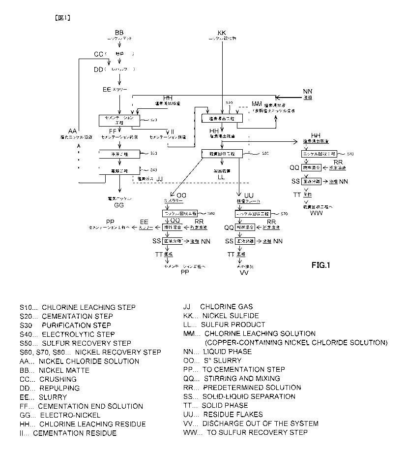
[0003]
Concretely, there is an electrolytic nickel manufacturing process (MCLE
process) by
chlorine-leaching, and its flow chart is illustrated herein. As illustrated
herein, the electrolytic
nickel manufacturing process comprises: a chlorine-leaching step S 11 for
generating a copper-
containing nickel chloride solution, which is a chlorine leachate, by chlorine-
leaching metal such
as nickel with nickel sulfide as a raw material; a cementation step S21 for
fixing univalent
copper ion by adding nickel matte and chlorine-leached residue to the copper-
containing nickel
chloride solution obtained by the chlorine-leaching step S11; a solution
purification step S31 for
removing impurities other than nickel from a cementation
CA 2957875 2018-12-10
CA 02957875 2017-02-10
t.
A
2
ST15PCTO9
final solution; an electrolytic step S41 for obtaining electrolytic nickel by
electrominning
from a nickel chloride solution obtained by the solution purification step
S31; and a sulfur
recovery step S51 for recovering product sulfur from the chlorine-leached
residue obtained by
the chlorine-leaching step S11.
[0004]
In the electrolytic nickel manufacturing process, producing the copper-
containing nickel
chloride solution via chlorine-leaching with nickel sulfide as the raw
material, manufacturing
the electrolytic nickel from the copper-containing nickel chloride solution,
and performing the
cementation treatment for fixing and removing copper in the copper-containing
nickel
chloride solution efficiently, are important for manufacturing high quality
electrolytic nickel.
As the technology relating to this cementation treatment, for example, it is
proposed in patent
document I.
[0005]
However, in the electrolytic nickel manufacturing process, as illustrated in
Fig. 7,
copper contained in nickel sulfide will be fixed and removed from the chlorine
leachate
(copper-containing nickel chloride solution) obtained via the chlorine-
leaching step S1 1 by
transporting it to the cementation step S21. A cementation residue containing
fixed copper
will be returned to the chlorine-leaching step Sll again, and in the chlorine-
leaching step S11,
univalent copper ion becomes bivalent copper ion by reacting with chlorine
gas, and nickel
will be leached by oxidation power of the bivalent copper ion. In addition,
copper contained
in nickel matte is also fixed and removed as well as copper contained in
nickel sulfide.
[0006]
In other words, in the chlorine-leaching step S1 1 and the cementation step
S21, copper
is circulating in a state maintaining a prescribed concentration (normally 40
g/L to 60 g/L).
Therefore, for example, when treatment capacity of nickel sulfide produced
from
hydrometallurgy is increased for the purpose of increasing manufacturing of
electrolytic
nickel, amount of copper circulated in a system of the electrolytic nickel
manufacturing
process will be increased inevitably.
[0007]
CA 02957875 2017-02-10
=
3 ST15PCTO9
By the way, in the cementation step S21, as mentioned above, the bivalent
copper ion
contained in the copper-containing nickel chloride solution will be reduced to
univalent
copper ion by nickel matte added as the raw material, and fixed by sulfur in
the
chlorine-leached residue.
[0008]
However, nickel metal or nickel subsulfide, which is a major form of nickel
matte,
prioritizes a function to reduce bivalent copper ion to univalent copper ion,
and univalent
copper ion generated by remained nickel metal and else will be fixed as copper
sulfide.
Therefore, when the amount of copper circulating in the system of the
electrolytic nickel
manufacturing process is increased, relatively, amount of nickel matte for
fixing as sulfide
after reducing to univalent copper ion from bivalent copper ion will be
decreased, so there is a
case that copper in the copper-containing nickel chloride solution cannot be
fixed and
removed surely and efficiently.
[0009]
Furthermore, when the amount of copper circulating in the system is increased
by
increased treatment of nickel sulfide as the raw material, along with
increased manufacturing
of electrolytic nickel, capability for removing copper will be insufficient
with amount of
nickel matte as well as conventional amount, in order to remove copper in the
copper-containing nickel chloride solution, therefore the amount of nickel
matte must be also
increased, so it will not be possible to remove copper efficiently and
effectively.
[0010]
From the above reasons, in patent document 1, it is not possible to respond to
the
increase of the amount of copper circulating in the system, so the cementation
treatment
capable of removing copper contained in the copper-containing nickel chloride
solution
efficiently and effectively is desired.
[0011]
In order to respond to this kind of demand, a technology for removing copper
efficiently and effectively by fixing copper by adding nickel matte and
chlorine-leached
residue after reducing copper by adding nickel sulfide to nickel chloride
solution containing
CA 02957875 2017-02-10
4 ST15PCTO9
copper (copper-containing nickel chloride solution) is proposed in patent
document 2, patent
document 3, and else. The technology described in patent document 2 and patent
document 3
have been applied in real operation, and as a result, most of the above
problems have been
resolved.
[0012]
Patent Document 1: Japanese Patent Application Laid-Open No. H11-080986
Patent Document 2: Japanese Patent Application Laid-Open No. 2012-107264
Patent Document 3: Japanese Patent Application Laid-Open No. 2012-026027
SUMMARY OF THE INVENTION
[0013]
However, by the technology described in patent document 2 and patent document
3, a
residue containing nickel, cobalt, and else is obtained as a byproduct from a
sulfur recovery
step. A part of this residue (Hereinafter, often referred to as "S slurry".)
is returned to the
chlorine-leaching step or the cementation step, and a part (Hereinafter, often
referred to as
"residue flaker".) is discharged out of the system. Also, as other byproduct,
chlorine-leached
residue is also generated.
[0014]
These byproducts respectively contains 5 wt% to 20 wt% of nickel, and
especially, the
residue flaker is discharged out of the system, so there is a problem that it
will be a loss of
nickel as a whole process. Also, about nickel contained in S slurry and
chlorine-leached
residue, they will be circulated in the system, so it will not be a loss, but
it is necessary to
operate while holding valuables in the process, so it is disadvantageous with
respect to
interest.
[0015]
In order to decrease nickel contained in these byproducts, increasing leaching
tank to
prolong leaching time or slurrying the byproducts again after solid-liquid
separation for
leaching at high concentration and else could be considered easily, but
equipment of leaching
tank or additional chlorine and water for repulping will be necessary, so it
is disadvantageous
with respect to material cost and water balance of a plant.
CA 2957875
[0016]
On the other hand, when performing the technology described in patent document
2 or patent
document 3 in real operation, it is necessary to configure cementation step to
be at least two
phase steps. For example, as illustrated herein, at first, in first
cementation step S22, reducing
copper by adding nickel sulfide to nickel chloride solution containing copper
(copper-containing
nickel chloride solution), and then, in second cementation step S23, it is
necessary to fix copper
by adding nickel matte and chlorine-leached residue.
[0017]
The two phase steps are a main continuing path through which most of treated
water in the
process passes, therefore, it is necessary to operate each step simultaneously
and suitably, so a
cost for controlling the steps in real operation will be high and it is
disadvantageous compared to
simple one phase step.
[0018]
From the above, in the electrolytic nickel manufacturing process by chlorine-
leaching, a
technology capable of decreasing nickel remaining in a byproduct by recovering
nickel from the
byproduct, and also, capable of simplifying the cementation step
simultaneously, is requested,
[0019]
The present invention is proposed considering these actual circumstances, and
a purpose of
the present invention is to provide a nickel recovery process capable of
decreasing nickel
remaining in a byproduct by recovering nickel from the byproduct of the
electrolytic nickel
manufacturing process by chlorine-leaching, and further, capable of
simplifying the cementation
step simultaneously.
[0020]
The inventors accomplished the present invention, as a result of keen
examination for
achieving the above purpose, by finding that it is possible to decrease nickel
remaining in the
byproduct by mixing the byproduct with prescribed aqueous solution when
recovering nickel
from the byproduct of the electrolytic nickel manufacturing process.
[0021]
CA 2957875 2018-12-10
CA 02957875 2017-02-10
6 ST15PCTO9
In other word, a nickel recovery process relating to the present invention for
achieving
the above purpose is a nickel recovery process for recovering nickel from a
byproduct of an
electrolytic nickel manufacturing process by chlorine-leaching, comprising: a
chlorine-leaching step for obtaining a chlorine leachate and a chlorine-
leached residue by
oxidizing and leaching nickel sulfide; a cementation step for fixing and
removing copper in
the chlorine leachate; a sulfur recovery step for obtaining a
sulfur¨containing solution and a
residue by solid-liquid separation after slurrying the chlorine-leached
residue in a melting
tank; and a nickel recovery step for obtaining slurry by adding an aqueous
solution with a
chlorine dissolving amount of 80 g/L to 390 g/L, and also, with a copper
concentration of 30
g/L to 70 g/L to the byproduct containing 5 wt% to 20 wt% of nickel and for
solid-liquid
separating the slurry into solid phase and liquid phase, wherein the liquid
phase is returned
into a transportation path from the chlorine-leaching step to the cementation
step.
[0022]
In the nickel recovery process, it is preferable that the slurry is having a
slurry
concentration that solid content is 130 g/L to 350 g/L.
[0023]
In the nickel recovery process, it is possible to return the solid phase into
the
cementation step, when the byproduct is slurry repulped from the residue.
[0024]
In the nickel recovery process, it is possible to return the slurry into the
cementation
step without solid-liquid separation, when the byproduct is slurry repulped
from the residue.
[0025]
In the nickel recovery process, it is possible to discharge the solid phase
out of a system
of the electrolytic nickel manufacturing process, when the byproduct is
adhering substances
adhered to an inner wall of the melting tank.
[0026]
In the nickel recovery process, it is possible to return the solid phase into
the sulfur
recovery step, when the byproduct is a part of the chlorine-leached residue.
[0027]
CA2957875
7
In the nickel recovery process, it is preferable to use the chlorine leachate
instead of the
aqueous solution.
[0028]
By the present invention, it is possible to decrease nickel remaining in the
byproduct, and
also, it is possible to simplify the cementation step simultaneously, by
recovering nickel from the
byproduct of the electrolytic nickel manufacturing process by chlorine-
leaching.
[0028A]
The present invention discloses and claims a nickel recovery process for
recovering nickel
from a byproduct of an electrolytic nickel manufacturing process, the nickel
recovery process
comprising: a chlorine-leaching step for obtaining a chlorine leachate and a
chlorine-leached
residue by oxidizing and leaching nickel sulfide; a cementation step for
fixing and removing
copper in the chlorine leachate; a sulfur recovery step for obtaining a
sulfur¨containing solution
and a residue by solid-liquid separation after slurrying the chlorine-leached
residue in a melting -
tank; and a nickel recovery step for obtaining a slurry by adding an aqueous
solution with a
dissolved chlorine amount of 80 g/L to 390 g/L, and also, with a copper
concentration of 30 g/L
to 70 g/L to the byproduct, which contains 5 wt% to 20 wt% of nickel, and for
solid-liquid
separating the slurry into a solid phase and a liquid phase, wherein the
liquid phase is returned
into a transportation path from the chlorine-leaching step to the cementation
step.
BRIEF DESCRIPTION OF THE SEVERAL VIEWS OF THE DRAWINGS
[0029]
Fig. 1 is a flowchart of electrolytic nickel manufacturing process by chlorine-
leaching
applying nickel recovery process relating to the present invention.
Fig. 2 is a graph showing a reaction time in examples 1 and 4 to 7 and a
change of oxidation-
reduction potential on the basis of Ag/AgCl.
Fig. 3 is a graph showing a reaction time in examples 2, 8 and 9 and a change
of oxidation-
reduction potential on the basis of Ag/AgCl.
Fig. 4 is a graph showing a reaction time in examples 1 to 3 and a change of
oxidation-
reduction potential on the basis of Ag/AgCl.
Fig. 5 is a graph showing a reaction time in example 1 and comparative
examples 1 and 4 and
CA 2957875 2019-06-26
7a CA
2957875
a change of oxidation-reduction potential on the basis of Ag/AgCl.
Fig. 6 is a graph showing a reaction time in example 2 and comparative
examples 2, 3 and 5
and a change of oxidation-reduction potential on the basis of Ag/AgCl.
Fig. 7 is a flowchart of conventional electrolytic nickel manufacturing
process by chlorine-
leaching.
Fig. 8 is a flowchart of conventional electrolytic nickel manufacturing
process by chlorine-
leaching (patent document 3).
DETAILED DESCRIPTION OF THE INVENTION
[0030]
It will be explained in detail about the concrete embodiments applying the
present invention
(Hereinafter, referred to as "present embodiment") along with the following
items. In addition,
the present invention will not be limited by the following embodiments, and
these embodiments
can be modified in various ways without departing from the gist of the present
CA 2957875 2018-12-10
CA 02957875 2017-02-10
=
8
ST15PCTO9
invention.
[0031]
1. Summary of nickel recovery process
2. Chlorine-leaching step
3. Cementation step
4. Solution purification step
5. Electrolytic step
6. Sulfur recovery step
7. Nickel recovery step using S slurry
8. Nickel recovery step using residue flaker
9. Nickel recovery step using chlorine-leached residue
[0032]
[1. Summary of nickel recovery process]
Nickel recovery process relating to the present embodiment is a process for
recovering
nickel from S slurry, residue flaker and chlorine-leached residue, which are
byproducts of an
electrolytic nickel manufacturing process by chlorine-leaching, in a nickel
recovery step S60,
a nickel recovery step S70 and a nickel recovery step S80, as illustrated in
Fig. 1.
[0033]
More specifically, explaining about the present embodiment using an
electrolytic nickel
manufacturing process applying a nickel recovery process. As illustrated in
Fig. I, an
electrolytic nickel manufacturing process comprises: a chlorine-leaching step
S 10 for
generating a copper-containing nickel chloride solution, which is a chlorine
leachate, by
chlorine-leaching metal such as nickel with nickel sulfide as a raw material;
and a
cementation step S20 for fixing univalent copper ion by adding nickel matte
and
chlorine-leached residue to the copper-containing nickel chloride solution
obtained by the
chlorine-leaching step S10.
[0034]
Further, as steps after the cementation step S20, the electrolytic nickel
manufacturing
process comprises: a solution purification step S30 for removing impurities
other than nickel
CA 02957875 2017-02-10
9 ST15PCTO9
from a cementation final solution; and an electrolytic step S40 for obtaining
electrolytic nickel
by electrowinning from a nickel chloride solution obtained from the solution
purification step
S30.
[0035]
Also, as steps after the chlorine-leaching step S10, the electrolytic nickel
manufacturing
process comprises: a sulfur recovery step S50 for recovering product sulfur
from the
chlorine-leached residue obtained from the chlorine-leaching step S10; a
nickel recovery step
S60 for stirring and mixing S slurry obtained from the sulfur recovery step
S50 added with a
prescribed solution; a nickel recovery step S70 for obtaining liquid phase and
solid phase by
solid-liquid separation after stirring and mixing a residue flaker obtained
from the sulfur
recovery step S50 added with a prescribed solution; and a nickel recovery step
S80 for
obtaining liquid phase and solid phase by solid-liquid separation after
stirring and mixing a
part of the chlorine-leached residue obtained from the chlorine-leaching step
S10 added with a
prescribed solution.
[0036]
In the electrolytic nickel manufacturing process, it is possible to decrease
nickel
remaining in each byproduct by recovering nickel through the above each steps,
and at the
same time, it is possible to achieve simplification of the cementation step
S20 in the
electrolytic nickel manufacturing process.
[0037]
[2. Chlorine-leaching step]
In a chlorine-leaching step S10, a copper-containing nickel chloride solution
is
generated as a chlorine leachate by oxidizing and leaching metal components
such as nickel
or copper by chlorine gas, for example with nickel sulfide manufactured by
hydrometallurgy
from nickel oxide ore as a raw material. The chlorine leachate containing
copper
(copper-containing nickel chloride solution) generated from the chlorine-
leaching step S10 is
transported to a cementation step S20.
[0038]
On the other hand, impurities mainly composed of sulfur remaining in solid
phase in
CA 02957875 2017-02-10
ST15PCTO9
chlorine-leaching step S10 will be chlorine-leached residue, and product
sulfur will be
collected through a sulfur recovery step S50 in the following description.
Also, a
chlorine-leached residue extracting a part of the chlorine-leached residue
will be collected of
nickel in the chlorine-leached residue in a nickel recovery step S80 in the
following
description.
[0039]
In addition, in electrolytic nickel manufacturing process, there is a case
that excess
copper will be removed by electrolytic deposition by arranging unillustrated
copper removal
electrolytic step, during transportation of the chlorine leachate (copper-
containing nickel
chloride solution) from the chlorine-leaching step S10 to a cementation step
S20 in the
following description.
[0040]
However, by applying nickel recovery process to the electrolytic nickel
manufacturing
process, it is possible to decrease oxidation-reduction potential on the basis
of Ag/AgC1 of
transported chlorine leachate (copper-containing nickel chloride solution).
Therefore, it is
possible to decrease electric power necessary for electrolysis, as ratio of
bivalent copper ion
with respect to univalent copper ion is decreased.
[0041]
[3. Cementation step]
In the cementation step S20, the copper-containing nickel chloride solution
generated in
the chlorine-leaching step S10 is transported and copper in the copper-
containing nickel
chloride solution is fixed and removed. In the cementation step S20, a slurry
repulped by
nickel chloride solution generated in the following step of an electrolytic
step S40 by grinding
a raw material of nickel matte produced for example from pyrometallurgy is
added to the
copper-containing nickel chloride solution.
[0042]
Also, in the cementation step S20, a chlorine-leached residue mainly composed
of
sulfur generated as a byproduct in the chlorine-leaching step S10 is added.
Further, in the
cementation step S20, S slurry generated as a byproduct in a sulfur recovery
step S50 may be
CA 02957875 2017-02-10
=
11 ST15PCTO9
added.
[0043]
In the cementation step S20, as indicated in the following reaction formula 1
and
reaction formula 2, copper in the copper-containing nickel chloride solution
is removed by
fixing it as copper sulfide, by reducing bivalent copper ion in the copper-
containing nickel
chloride solution and sulfur in the chlorine-leached residue to univalent
copper ion and
bivalent sulfur ion by reduction power of nickel subsulfide and nickel metal
in nickel matte.
[0044]
Nic-1-2CuC12-->NiC12+2CuCl = = = (Reaction Formula 1)
Ni 4-S +2CuCl-->1\liC12+Cu2S = = = (Reaction Formula 2)
[0045]
In the cementation step S20, nickel in a solution in which copper has been
fixed and
removed will be bivalent nickel ion, and its solution will be transported to
the solution
purification step S30 as a cementation final solution. On the other hand,
sulfide of copper
remaining in solid phase by fixation or unreacted nickel will be transported
to the
chlorine-leaching step S10 again as a cementation residue.
[0046]
As a reaction temperature in the cementation step S20, preferably it is 70 C
to 100 C,
more preferably it is 80 C to 90 C. When the temperature condition is less
than 70 C, it will
be difficult to reduce bivalent copper ion remaining in the copper-containing
nickel chloride
solution to univalent copper ion, and a progress of reaction to fix univalent
copper ion by
sulfur will be stagnated.
[0047]
Therefore, in the cementation step S20, by setting a temperature condition to
70 C or
more, it is possible to reduce remaining bivalent copper ion to univalent
copper ion, and it is
possible to progress a reaction to fix the univalent copper ion efficiently by
sulfur.
[0048]
In addition, also for cobalt and copper in nickel matte, unreacted substance
will be
CA 02957875 2017-02-10
12 ST15PC109
transported to the chlorine-leaching step S10 as the cementation residue, and
metal ion will be
transported to the solution purification step S30 as the cementation final
solution, by similar
reaction as nickel.
[0049]
[4. Solution purification step]
In the solution purification step S30, the cementation final solution is
transported from
the cementation step S20, and impurities other than nickel such as iron,
cobalt and copper
contained in the cementation final solution are removed by solution
purification treatment, for
example oxidizing and neutralizing process and else. Concretely, in the
solution purification
step S30, there are a deironization step, a cobalt removal step, a deleading
step, and a
dezincification step, as unillustrated main steps.
[0050]
[5. Electrolytic step]
In the electrolytic step S40, electrolytic nickel is manufactured by
electrowinning, using
nickel chloride solution obtained by the solution purification step S30. In
the electrolytic step
S40, at cathode side, nickel ion in nickel chloride solution deposits as metal
and electrolytic
nickel will be generated. Also, at anode side, chlorine ion in nickel chloride
solution generates
as chlorine gas and it will be used in the chlorine-leaching step S10 and
else.
[0051]
[6. Sulfur recovery step]
In the sulfur recovery step S50, the chlorine-leached residue obtained in the
chlorine-leaching step S 10 is heated in the melting tank to melt contained
sulfur content, and
the chlorine-leached residue will be slurried, and this slurry is charged into
a solid-liquid
separation device to obtain a product sulfur as liquid phase. Also, residue
obtained as solid
phase is grinded and repulped to obtain S slurry. Nickel in the obtained S
slurry is recovered
in the following nickel recovery step S60.
[0052]
Also, when slurrying the chlorine-leached residue, the residue, which cannot
be charged
into the solid-liquid separation device and attaches to inner wall of the
melting tank with
CA 02957875 2017-02-10
=
13
STI5PCTO9
insufficient melting even by heating, will be obtained, but this residue is
called residue flaker.
Nickel in the obtained residue flaker will be recovered in the following
nickel recovery step
S70.
[0053]
In addition, when slurrying the chlorine-leached residue, it is possible to
use a solution,
which does not contain cupric chloride, but there is a problem that leaching
speed decreases
as the concentration of cupric chloride at the time of mixing treatment in the
following nickel
recovery step S60 decreases. Further, when using the solution, which does not
contain cupric
chloride, it is necessary to evaporate excess water by heating and else, in
order to restore
water balance in the step, and cost for applying thermal energy and else will
be increased.
[0054]
[7. Nickel recovery step using S slurry]
In a nickel recovery step S60, after obtaining slurry by mixing and stirring S
slurry
obtained in the sulfur recovery step S50 and a prescribed solution, liquid
phase and solid
phase are obtained by solid-liquid separation.
[0055]
In the nickel recovery step S60, the obtained liquid phase is returned into a
transportation path from the chlorine-leaching step SIO to the cementation
step S20, and joins
the chlorine-leached residue. Also, the obtained solid phase is charged into
the cementation
step S20. In addition, in the nickel recovery step S60, the obtained slurry
may be charged into
the cementation step S20 without solid-liquid separation.
[0056]
Here, in the nickel recovery step S60, it is preferable that slurry
concentration of the
obtained slurry is adjusted that solid content will be 130 g/L to 350 g/L.
[0057]
When the solid content is less than 130 g/L, a problem occurs that it will be
difficult to
restore water balance of a plant, as an amount of solution will be increased
too much, or a
problem occurs that a propulsion of reduction into univalent copper ion from
bivalent copper
ion will be decreased and it will be time-consuming, when a grade of nickel in
S slurry,
CA 02957875 2017-02-10
14 ST15PCT09
which is a byproduct of the electrolytic nickel manufacturing process, is low.
[0058]
On the other hand, when the solid content is more than 350 g/L, a problem
occurs that a
special pump will be necessary for transportation of slurry thereafter. as a
viscosity of slurry
will be too high.
[0059]
For stirring of S slurry and prescribed solution, a publicly known technology
is applied
for effective contact of the S slurry and the prescribed solution. In other
words, in the nickel
recovery step S60, a stirring means with ability to stir in a range of amount
of solid content in
the above slurry concentration may be selected.
[0060]
When joining the slurry obtained by mixing and stirring S slurry and
prescribed
solution into the chlorine leachate, an aqueous solution containing at least
80 g/L to 390 g/L
as chlorine dissolving amount, and also, containing at least 30 g/L to 70 g/L
as copper
concentration, is used as the prescribed solution. In this way, 15 wt% to 20
wt% of nickel
remained in S slurry is leached by chlorine dissolved in the prescribed
solution, so it is
possible to decrease nickel remaining in finally obtained solid phase.
Concretely, nickel in the
solid phase can be decreased to be the extent of 11 wt% to 16 wt%.
[0061]
Leached nickel will be incorporated into finally obtained liquid phase, and
joined to the
chlorine leachate by returning the liquid phase into the transportation path
from the
chlorine-leaching step S10 to the cementation step S20, so amount of nickel
contained in the
chlorine leachate increases, and nickel leaching rate in the chlorine-leaching
step S10
increases seemingly.
[0062]
In the nickel recovery step S60, a water balance in a system will be broke, as
prescribed
solution is added, but it will be fine by a countermeasure to discharge a
water in the system,
which almost does not contain nickel, for example a barren solution
(unillustrated), to the
amount matches the added water, or by a countermeasure to evaporate the water
in the system
CA 02957875 2017-02-10
15 ST15PCTO9
by heating, and else.
[0063]
As the prescribed solution, chlorine leachate containing copper generated from
the
chlorine-leaching step S10 (copper-containing nickel chloride solution), or
aqueous solution
containing chloride ion such as nickel chloride solution discharged in the
electrolytic step S40
is preferable as concentration of cupric chloride will not be decreased at the
time of mixing
treatment, and aqueous solution containing cupric chloride is more preferable.
For example,
when chlorine leachate (copper-containing nickel chloride solution) is used,
restoration
measures for broken water balance in the system will not be necessary, and
more efficient
operation will be possible.
[0064]
[8. Nickel recovery step using residue flaked
In a nickel recovery step S70, after obtaining slurry by mixing and stirring a
residue
flaker obtained in the sulfur recovery step S50 and a prescribed solution,
liquid phase and
solid phase are obtained by solid-liquid separation. In addition, about slurry
concentration,
stirring means, and prescribed solution, they are similar as the nickel
recovery step S60, so the
explanation will be abbreviated here.
[0065]
In the nickel recovery step S70, obtained liquid phase is returned into a
transportation
path from the chlorine-leaching step SI 0 to the cementation step S20, and
joins the chlorine
leachate. Also, obtained solid phase is discharged out of the system.
[0066]
Here, when joining the liquid phase to the chlorine leachate, aqueous solution
similar as
prescribed solution of nickel recovery step S60 is used as the prescribed
solution. In this way,
wt% to 7 wt% of nickel remaining in the residue flaker is leached by chlorine
dissolved in
the prescribed solution, and not only that nickel remaining in finally
obtained solid phase will
be decreased to the extent of 2 wt%, but also it is possible to decrease a
loss of nickel in the
whole process.
[0067]
CA 02957875 2017-02-10
16 ST15PCTO9
Leached nickel is incorporated in finally obtained liquid phase, and joined to
the
chlorine leachate by returning the liquid phase into the transportation path
from the
chlorine-leaching step S10 to the cementation step S20, so amount of nickel
contained in the
chlorine leachate increases, and nickel leaching rate in the chlorine-leaching
step S10
increases seemingly.
[0068]
In the nickel recovery step S70, a water balance in a system will be broke, as
prescribed
solution is added, but it will be fine by a countermeasure to discharge a
water in the system,
which almost does not contain nickel, for example a barren solution
(unillustrated), to the
amount matches the added water, or by a countermeasure to evaporate the water
in the system
by heating, and else.
[0069]
Liquid amount of liquid phase obtained by solid-liquid separating slurry is
equal to
liquid amount of prescribed solution. Therefore, weight of obtained solid
phase is equal to
weight of residue flaker obtained in the sulfur recovery step S51 and
discharged out of the
system in the prior art illustrated in Fig. 7, so there will be no harmful
effect to the whole
process even if the solid phase is discharged out of the system.
[0070]
[9. Nickel recovery step using chlorine-leached residue]
In a nickel recovery step S80, after obtaining slurry by mixing and stirring a
chlorine-leached residue partially extracted from a chlorine-leached residue
charged into the
sulfur recovery step S50 and a prescribed solution, liquid phase and solid
phase are obtained
by solid-liquid separation. In addition, about slurry concentration, stirring
means, and
prescribed solution, they are similar as the nickel recovery step S60, so the
explanation will be
abbreviated here.
[0071]
In the nickel recovery step S80, obtained liquid phase is returned into a
transportation
path from the chlorine-leaching step S10 to the cementation step S20, and
joins the chlorine
leachate. Also, obtained solid phase is charged into the next step of sulfur
recovery step S50.
CA 02957875 2017-02-10
17 ST15PCTO9
[0072]
Here, when joining the liquid phase to the chlorine leachate, aqueous solution
similar as
prescribed solution of nickel recovery step S60 is used as the prescribed
solution. In this way,
wt% to 7 wt% of nickel remaining in the chlorine-leached residue is leached by
chlorine
dissolved in the prescribed solution, and it is possible to decrease amount of
nickel remaining
in finally obtained solid phase. Concretely, it is possible to decrease the
amount of nickel to
the extent that nickel in the solid phase will be to the extent of 3 wt% to 5
wt%.
[0073]
Leached nickel is incorporated in finally obtained liquid phase, and joined to
the
chlorine leachate by returning the liquid phase into the transportation path
from the
chlorine-leaching step S10 to the cementation step S20, so amount of nickel
contained in the
chlorine leachate increases, and nickel leaching rate in the chlorine-leaching
step S10
increases seemingly.
[0074]
In the nickel recovery step S80, a water balance in a system will be broke, as
prescribed
solution is added, but it will be fine by a countermeasure to discharge a
water in the system,
which almost does not contain nickel, for example a barren solution
(unillustrated), to the
amount matches the added water, or by a countermeasure to evaporate the water
in the system
by heating, and else.
[0075]
In the nickel recovery step, nickel can be recovered by performing at least
one step of
nickel recovery step S60, nickel recovery step S70, and nickel recovery step
S80, and it will
be possible to decrease nickel remaining in each byproduct. Within each nickel
recovery step,
it is preferable to perform the nickel recovery step S70, as nickel discharged
out of the system
(loss of nickel) will be decreased.
[0076]
Also, by performing the nickel recovery step S60 or the nickel recovery step
S70 in
addition to the nickel recovery step S80, or by performing every nickel
recovery steps. the
chlorine-leached residue after recovering nickel by the nickel recovery step
S80 will be
CA 02957875 2017-02-10
=
18
ST15PCT09
charged into the sulfur recovery step S50. Then, recovery of nickel will be
performed further,
and it is preferable as recovery rate of nickel will be higher than performing
the nickel
recovery step individually.
[0077]
The nickel recovery step is to apply the nickel recovery step, in other words,
to add the
nickel recovery step S60, nickel recovery step S70, and nickel recovery step
S80, to a
conventional electrolytic nickel manufacturing process as illustrated in Fig.
7.
[0078]
In the conventional electrolytic nickel manufacturing process, the cementation
treatment capable of removing copper contained in copper-containing nickel
chloride solution
efficiently and effectively, even when amount of copper circulated in the
system is increased,
has been desired. However, in the nickel recovery process, the above problem
will not be
occurred, and further, cementation step can be performed in one step. Present
inventors are
considering about its reason as follow.
[0079]
Copper contained in nickel matte and nickel chloride circulates in the system
similar to
the conventional electrolytic nickel manufacturing process. Therefore, in a
purpose of
increasing production of electrolytic nickel, for example, when treatment
capacity of nickel
chloride produced from hydrometallurgy is increased, amount of copper
circulated in the
system of electrolytic nickel manufacturing process is also increased
inevitably.
[0080]
In other words, when amount of copper circulating in the system of
conventional
electrolytic nickel manufacturing process illustrated in Fig. 7 is increased,
the chlorine
leachate obtained from the chlorine-leaching step Sll will be to the extent of
550 mV at
oxidation-reduction potential on the basis of Ag/AgC1, and coexisting copper
ion will be in
the state with excess bivalent copper ions, and it will be short of reduction
power of nickel
metal throughout the cementation step S21, as univalent copper ion will be
reduced at first.
[0081]
In this point, when applying nickel recovery process relating to the present
embodiment
CA 02957875 2017-02-10
19 ST15PCTO9
to the conventional electrolytic nickel manufacturing process. as illustrated
in Fig. 1, by
joining liquid phase obtained by solid-liquid separation of slurry obtained by
mixing and
stirring byproducts of electrolytic nickel manufacturing process (S slurry,
residue flaker and
chlorine-leached residue) and prescribed solution to chlorine leachate by
returning the liquid
phase into transportation path from the chlorine-leaching step S 10 to the
cementation step S20,
ratio of univalent copper ion and bivalent copper ion in the chlorine leachate
shifts to the side
of univalent copper ion, and the state with excess bivalent copper ions will
be resolved, so it is
possible to maintain the reduction power of nickel metal sufficiently.
[0082]
Namely, liquid phase obtained by solid-liquid separation of slurry obtained by
mixing
and stirring each byproduct and prescribed solution, is the liquid phase
leaching nickel
remaining in each byproduct, so dissolved chlorine will be consumed as nickel
chloride. In
association with this, coexisting copper ion will be decreased to the extent
of 350 mV at
oxidation-reduction potential on the basis of Ag/AgC1, in which existence
ratio of univalent
copper ion and bivalent copper ion will be in balance, so, for example, a
first phase
cementation step (first cementation step S22) by nickel chloride, which was
necessary in
conventional electrolytic nickel manufacturing process illustrated in Fig. 8
will be
unnecessary.
[0083]
As explained in the above, in the nickel recovery process, chlorine and
copper-containing aqueous solution with a chlorine dissolving amount of 80 g/L
to 390 g/L,
and also, with a copper concentration of 30 g/L to 70 g/L, is added to each
byproduct of
electrolytic nickel manufacturing process. Further, solid content in the
concentration of slurry
obtained by adding chlorine and copper-containing aqueous solution to each
byproduct is
adjusted to 130 g/L to 350 g/L.
[0084]
By applying such nickel recovery process to the electrolytic nickel
manufacturing
process, it is possible to recover nickel from the byproducts of the
electrolytic nickel
manufacturing process by chlorine-leaching efficiently, and to decrease nickel
remaining in
CA 02957875 2017-02-10
20 ST15PCTO9
the byproducts, and also, it is possible to achieve simplification of the
cementation step
simultaneously.
EXAMPLES
[0085]
The present invention is further explained in detail by examples and
comparative
examples in the following descriptions, but the present invention will not be
limited at all by
these examples.
[0086]
In addition, the common conditions in the examples and comparative examples
are as
follow, and starting solution and raw materials to be used are indicated in
table 1 and table 2.
[0087]
[Table 1]
Component grade (weight%)
Raw material
Ni Co Cu Fe
S slurry 19.9 2.8 0.30 0.22 68.8
Residue flaker 5.4 0.7 0.07 0.07 90.0
Chlorine-leached residue 7.2 0.9 0.04 0.07 84.4
[0088]
[Table 2]
Oxidation-reduction Component
concentration (g/L)
Starting solution No. pH potential
Ag/AgCI (mV) Ni Cu Cl
Starting solution 1 0.34 580 140 38 310
Starting solution 2 -0.43 573 , 180 54 300
Starting solution 3 -1.03 578 230 70 390
Starting solution 4 0.03 696 0 52 80
[0089]
(Adjustment of reaction starting solution)
CA 02957875 2017-02-10
21 ST15PCTO9
400 mL of a starting solution 1 indicated in table 2 was poured into 500 mL of
separable flask with baffle plate, and heated to be 100 C to 105 C in oil bus
while stirring in
rotational speed of 300 rpm. In addition, starting solutions 2 to 4 indicated
in table 2 were also
adjusted as well as the starting solution 1.
[0090]
(Example 1)
In example 1, 140 g of S slurry was poured into the starting solution 1
heated by the
previous adjustment process, and liquid temperature was adjusted so that the
reaction
temperature would be 100 C to 110 C, and reacted for four hours.
[0091]
After reaction, in the example 1, solid-liquid separation was performed by
suction
filtration, and leached residue 1 (solid phase) and leachate 1 (liquid phase)
were obtained.
[0092]
(Example 2)
In example 2, it was performed as same as the example 1 except that 140 g of
residue
flaker was poured into the starting solution 1, and leached residue 2 (solid
phase) and leachate
2 (liquid phase) were obtained.
[0093]
(Example 3)
In example 3, it was performed as same as the example 1 except that 140 g of
chlorine-leached residue was poured into the starting solution 1, and leached
residue 3 (solid
phase) and leachate 3 (liquid phase) were obtained.
[0094]
(Example 4)
In example 4, it was performed as same as the example 1 except that 116 g of S
slurry
was poured into the starting solution 1, and leached residue 4 (solid phase)
and leachate 4
(liquid phase) were obtained.
[0095]
CA 02957875 2017-02-10
22 ST15PCT09
(Example 5)
In example 5, it was performed as same as the example 1 except that 72 g of S
slurry
was poured into the starting solution 1, and leached residue 5 (solid phase)
and leachate 5
(liquid phase) were obtained.
[0096]
(Example 6)
In example 6, it was performed as same as the example 1 except that 52 g of S
slurry
was poured into the starting solution 1, and leached residue 6 (solid phase)
and leachate 6
(liquid phase) were obtained.
[0097]
(Example 7)
In example 7, it was performed as same as the example 1 except that 30 g of S
slurry
was poured into the starting solution 1, and leached residue 7 (solid phase)
and leachate 7
(liquid phase) were obtained.
[0098]
(Example 8)
In example 8, it was performed as same as the example 1 except that 72 g of
residue
flaker was poured into the starting solution 1, and leached residue 8 (solid
phase) and leachate
8 (liquid phase) were obtained.
[0099]
(Example 9)
In example 9, it was performed as same as the example 1 except that 30 g of
residue
flaker was poured into the starting solution 1, and leached residue 9 (solid
phase) and leachate
9 (liquid phase) were obtained.
[0100]
The measurements of concentration and grade of each component contained in the
leached residues 1 to 9 and the leachates 1 to 9 obtained by the examples 1 to
9 were
performed by 1CP emission spectral analysis. And the analysis results thereof
were indicated
altogether in table 3 and table 4.
CA 02957875 2017-02-10
23 ST15PCTO9
[0101]
(Comparative Example 1)
In comparative example 1, it was performed as same as the example 1 except
that 140 g
of S slurry was poured into 400mL of starting solution 2 heated by the
adjustment process,
and leached residue 10 (solid phase) and leachate 10 (liquid phase) were
obtained.
[0102]
(Comparative Example 2)
In comparative example 2, it was performed as same as the example I except
that 140 g
of chlorine-leached residue was poured into the starting solution 2 heated by
the adjustment
process, and leached residue 11 (solid phase) and leachate 11 (liquid phase)
were obtained.
[0103]
(Comparative Example 3)
In comparative example 3, it was performed as same as the example 1 except
that 140 g
of chlorine-leached residue was poured into 400mL of starting solution 3
heated by the
adjustment process, and leached residue 12 (solid phase) and leachate 12
(liquid phase) were
obtained.
[0104]
(Comparative Example 4)
<Preparation of Starting Solution 4>
In comparative example 4, starting solution 4 was obtained by dissolving
reagent of
cupric chloride in pure water, and by adjusting it to pH 0.00 (25 C) by
hydrochloric acid.
Copper concentration of the obtained starting solution 4 was 52 g/L, and
dissolved chlorine
concentration of the obtained starting solution 4 was 80 g/L.
[0105]
In the comparative example 4, it was performed as same as the example 1 except
that
140 g of S slurry was poured into 400mL of starting solution 4 heated by the
adjustment
process, and leached residue 13 (solid phase) and leachate 13 (liquid phase)
were obtained.
[0106]
(Comparative Example 5)
CA 02957875 2017-02-10
24 ST15PCTO9
In comparative example 5, it was performed as same as the example 1 except
that 140 g
of chlorine-leached residue was poured into the starting solution 4 heated by
the adjustment
process, and leached residue 14 (solid phase) and leachate 14 (liquid phase)
were obtained.
[0107]
The measurements of concentration and grade of each component contained in the
leached residues 10 to 14 and the leachates 10 to 14 obtained by the
comparative examples 1
to 5 were performed by ICP emission spectral analysis. And the analysis
results thereof were
indicated altogether in table 3 and table 4.
Leached residue grade (weight%) Reaction condition i--
cr co,
Leached residue Ns. Test No.
Ni Co Cu Fe S Starting sdiltion Raw material
Slurry concentration
Leached residue 1 1 5.6 2.4 5.7 0.17 69.6 Example 1
S slurry
Leached residue 2 2.9 0.5 4.2 0.04 86.3
Example 2 Residue flaker 350g/L
Leached residue 3 4.9 0.8 0.2 0.05 85.1 Example 3
Chlorine-leached residue
Leached residue 4 15.5 2.4 5.7 0.17 70.3
Example 4 290g/L
Leached residue 5 13.3 2.2 8.3 0.15 66.5
Example 5 180g/L
Stating solutionl 3' slurry
Leached residue 6 11.8 2.1 10.6 0.15 70.4
Example 6 130g/L
Leached residue 7 8.9 1.6 15.8 0.11 69.9
Example 7 75g/L
Leached residue 8 2.2 0.4 2.9 0.03 91.5
Example 8 180g/L
Residue flaker
Leached residue 9 2.4 0.4 0.1 0.03 88.4
Example 9 75g/L
tJ
Leached residue 10 15.9 2.5 1.6 0.18 73.9
Comparative example 1 S slurry
Strtisg solution 2
Leached residue 11 3.8 0.6
0.2 0.05 89.5 Comparative example 2 17'
Chlorine-leached residue
Leached residue 12 2.6 0.5 0.3 0.03 91.1 Comparative example
3 Starting siktion 3
350g/L
Leached residue 13 18.5 2.7 3.3 0.19 69.2
Comparative example 4 S slurry
String solution 4
Leached residue 14 6.9 1.0 0.3 0.07 86.6 Comparative
example 5 Chlorine-leached residue
c/P
,
,
H c'
Oxidation-reduction Leachate concentration (g/L) Reaction condition
cr c)
Leachate No. pH potential Test No.
Ag/Ag01(mV) Ni Cu Cl Starting solution Raw
material Slurry concentration -P
Leachate 1 -0.19 353 , 160 16 240 Example 1
S slurry
Leachate 2 -0.06 454 150 31 230
Example 2 Residue flaker 350g/L
Leachate 3 -0.38 405 160 38 290 Example 3
Chlorine-leached residue
Leachate 4 -0.08 340 150 18 260
Example 4 290g/L
Leachate 5 -0.11 369 150 20 270
Example 5 180g/L
Starting solition 1 S slurry
Leachate 6 -0.21 392 145 23 290
Example 6 130g/L
Leachate 7 , -0.15 448 140 25 310
Example 7 75g/L
Leachate 8 0.18 477 140 32 240
Example 8 180g/L g
0
Residue flaker
Leachate 9 0.21 509 135 35 260
Example 9 75g/L '
0,
-,
0
-
...3
Leachate 10 -0.77 359 190 57 310 Comparative
example 1 S slurry
Steil solution /
cr=N ,,,
Leachate 11 -0.78 419 200 54
300 Comparative example 2 ,
1
Chlorine-leached residue
-
Leachate 12 -1.30 441 260 72
390 Comparative example 3 Starting solution 3 1-
350g/L
0
Leachate 13 -0.23 426 5.9 39 65 Comparative
example 4 S slurry
Starting solution 4
Leachate 14 -0.17 435 4.6 53 80 Comparative
example 5 Chlorine-leached residue
cio
H
CA
'V
r)
H
c)
v.:)
CA 02957875 2017-02-10
27 ST15PCTO9
[0110]
In the examples 1 to 9, as indicated in table 3 and table 4, leaching of
nickel was
promoted by increase of addition amount of each raw material, and nickel
concentration of
leachate was increased, on the other hand, chlorine concentration was
decreased. Also, in the
examples 1 to 9, along with the decrease of chlorine concentration, copper
concentration was
also decreased. This is because consumption of dissolved choline and reduction
of bivalent
copper ion into univalent copper ion has progressed, and copper was fixed and
removed to
solid phase (leached residue) side as copper sulfide.
[0111]
In the examples 1 to 9, "reaction time and change of oxidation-reduction
potential on
the basis of Ag/AgCl", when each raw material was leached using the starting
solution 1, were
measured, and measurement results were illustrated as graph in Figs. 2 to 4.
[0112]
In the examples 1 to 9, as illustrated in Figs. 2 to 4, when addition amount
of each raw
material was increased (slurry concentration was increased), oxidation-
reduction potential on
the basis of Ag/AgC1 of the leachate was decreased quickly.
[0113]
As illustrated in Fig. 2, it was found that oxidation-reduction potential on
the basis of
Ag/AgC1 became constant (equilibrium in reaction) in the order of 330 mV to
350 mV, and
that further addition of each raw material or extension of reaction time was
not necessary.
[0114]
In addition, as illustrated in Fig. 4, with respect to reactivity of each raw
material, S
slurry was fastest, and then chlorine-leached residue, and residue flaker was
slowest.
[0115]
In the comparative examples 1 to 5, "reaction time and change of oxidation-
reduction
potential on the basis of Ag/AgCl", when each raw material was leached using
the starting
solutions 2 to 4, were measured, and measurement results were illustrated as
graph in Figs. 5
and 6. In addition, in Figs. 5 and 6, the results of examples 1 and 2 using
starting solution 1
were also described for comparison.
CA 02957875 2017-02-10
28 ST15PCT09
[0116]
In the comparative examples 1 to 5, as illustrated in Figs. 5 and 6, as copper
ion
concentration in the starting solution was increased, the amount of bivalent
copper ion, which
requires reduction, was increased, so decreasing speed of oxidation-reduction
potential on the
basis of Ag/AgC1 became slow.
[0117]
Also, in the comparative examples 4 and 5 using the starting solution 4,
oxidation-reduction potential on the basis of Ag/AgC1 of final solution became
balanced
around 420 mV to 430 mV. This result was different from the other examples and
comparative
examples, but it could be assumed that balance of equilibrium in reaction
indicated in the
following reaction formulas 1 and 2 became different, as all copper ion
contained in the
starting solution were bivalent copper ion, and as amount of chloride ion was
also small.
[0118]
Ni +2CuC12¨>NiC12+2CuCl= = = (Reaction Formula 1)
Ni SQ-F2CuCl---NiC12+Cu2S = = = (Reaction Formula 2)
[0119]
As mentioned above, from the results of the examples 1 to 9 and the
comparative
examples 1 to 5, it was understood that it is possible to recover nickel by
slurrying the residue
again by aqueous solution after solid-liquid separating the residue (for
example,
chlorine-leached residue of Fig. 1) produced in the chlorine-leaching step
(for example,
chlorine-leaching step S10 of Fig. 1), and by performing mixing treatment with
solution
containing cupric chloride. In addition, it was considered that recovery
amount of nickel is
proportional with the amount of excess chloride ion of liquid phase, so it was
understood that
it is possible to recover nickel more efficiently if copper ion concentration
is higher.