Language selection

Search

Patent 2957936 Summary

Third-party information liability

Some of the information on this Web page has been provided by external sources. The Government of Canada is not responsible for the accuracy, reliability or currency of the information supplied by external sources. Users wishing to rely upon this information should consult directly with the source of the information. Content provided by external sources is not subject to official languages, privacy and accessibility requirements.

Claims and Abstract availability

Any discrepancies in the text and image of the Claims and Abstract are due to differing posting times. Text of the Claims and Abstract are posted:

  • At the time the application is open to public inspection;
  • At the time of issue of the patent (grant).
(12) Patent: (11) CA 2957936
(54) English Title: BIRD FEEDER
(54) French Title: MANGEOIRE POUR OISEAUX
Status: Granted and Issued
Bibliographic Data
(51) International Patent Classification (IPC):
  • A01K 39/01 (2006.01)
  • A01K 39/012 (2006.01)
(72) Inventors :
  • THORN, JAMES JOHN (United Kingdom)
(73) Owners :
  • JAMES JOHN THORN
  • OAKTHRIFT CORPORATION LTD
(71) Applicants :
  • JAMES JOHN THORN (United Kingdom)
  • OAKTHRIFT CORPORATION LTD (United Kingdom)
(74) Agent: ADE & COMPANY INC.
(74) Associate agent:
(45) Issued: 2020-09-01
(86) PCT Filing Date: 2015-02-05
(87) Open to Public Inspection: 2015-08-20
Examination requested: 2020-01-23
Availability of licence: N/A
Dedicated to the Public: N/A
(25) Language of filing: English

Patent Cooperation Treaty (PCT): Yes
(86) PCT Filing Number: PCT/GB2015/050310
(87) International Publication Number: GB2015050310
(85) National Entry: 2016-11-24

(30) Application Priority Data:
Application No. Country/Territory Date
1402398.0 (United Kingdom) 2014-02-12

Abstracts

English Abstract


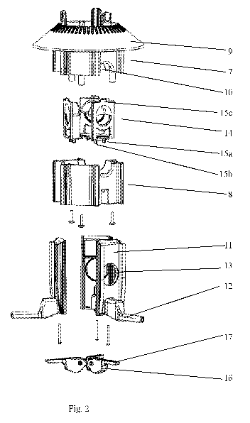
A hanging bird feeder comprises a hanging attachment that allows a user to
hang the feeder, a feed reservoir, and a plurality of individual perches
arranged around the periphery of the bird feeder and adjacent respective
feed-dispensing openings. The feeder has a plurality of shrouds each
connected to respective perches and the perches are biased to rest in a first
position where their associated shrouds are not covering their respective
openings. The perches are independently moveable under weight to a second
position where their respective shrouds are covering their respective
openings. The feeder has a plurality of pivoting members pivotally attached at
first ends under the feed reservoir and having free ends that extend under
respective perches. The perches are biased to rest in their first position by
means of torsion springs acting on the pivoting members and located adjacent
the first ends of respective pivoting members.


French Abstract

L'invention concerne une mangeoire suspendue pour oiseaux comprenant une fixation de suspension qui permet à un utilisateur de suspendre la mangeoire, un réservoir de nourriture, et une pluralité de perchoirs individuels (12) agencés autour de la périphérie de la mangeoire pour oiseaux et à côté d'ouvertures de distribution de nourriture (13) respectives. La mangeoire est dotée d'une pluralité d'éléments couvrants (11) respectivement reliés à des perchoirs associés et ces perchoirs sont sollicités vers une première position dans laquelle les éléments couvrants associés ne recouvrent pas les ouvertures respectives. Les perchoirs sont déplaçables de manière indépendante sous l'effet du poids vers une deuxième position dans laquelle les éléments couvrants respectifs recouvrent les ouvertures respectives. La mangeoire comporte une pluralité d'éléments pivotants (16) fixés de manière pivotante au niveau de premières extrémités sous le réservoir de nourriture et ayant des extrémités libres qui s'étendent sous les perchoirs respectifs. Les perchoirs sont sollicités vers leur première position au moyen de ressorts de torsion agissant sur les éléments pivotants et situés à côté des premières extrémités d'éléments pivotants respectifs.

Claims

Note: Claims are shown in the official language in which they were submitted.


CLAIMS:
1. A hanging bird feeder comprising:
a hanging attachment that allows a user to hang the bird feeder;
a feed reservoir coupled to the hanging attachment;
a plurality of feed dispensing openings formed around a periphery of
the feed reservoir;
a plurality of individual perches arranged around a periphery of the bird
feeder;
a plurality of shrouds movable on the feed reservoir;
wherein each of the plurality of feed dispensing openings has an
associated individual perch of the plurality of individual perches located
adjacent to the corresponding feed dispensing opening and an associated
individual shroud of the plurality of shrouds movable to one of cover or
expose
the-corresponding feed dispensing opening;
wherein each associated individual perch is biased to rest in a first
position where the associated individual shroud exposes the corresponding
feed dispensing opening;
wherein each associated individual perch is independently movable to
a second position where the associated individual shroud is covering the
corresponding feed dispensing opening in response to a force on the
associated individual perch in excess of a predetermined value is; and
a plurality of pivoting members, wherein each of the plurality of pivoting
members has a pivotally attached adjacent first end under the feed reservoir
and extends radially towards a free end that extends under an individual one
of the plurality of individual perches applying force to an underside of the
individual one of the plurality of individual perches;
wherein each of the plurality of individual perches is biased to rest in
the first position by means of a torsion spring acting on a respective
pivoting
member;
and wherein each of the plurality of individual perches extends
perpendicularly to the associated individual shroud, each torsion spring
allowing the respective pivoting member to move a corresponding perch, the
8

corresponding perch remaining horizontal as the corresponding perch moves
vertically down the bird feeder.
2. The bird feeder of claim 1 wherein the pivoting members are
housed within individual recesses formed in a lower housing portion of the
bird
feeder.
3. The bird feeder of claim 1 or 2 wherein each of the plurality of
pivoting members extend into respective recesses formed in an underside of a
respective individual perch of the plurality of individual perches.
4. The bird feeder of any one of claims 1 to 3 wherein each torsion
spring is located at a pivot of the respective pivoting member.
5. The bird feeder of one of claims 1 to 4 wherein the associated
individual perch of the plurality of individual perches and the associated
individual shroud of the plurality of shrouds are formed in one piece.
6. The bird feeder of one of claims 1 to 5 wherein the associated
individual perch and the associated individual shroud are formed separately
and are mechanically connected.
7. The bird feeder of one of claims 1 to 6 wherein each of the
plurality of shrouds are slidably mounted on the bird feeder.
8. The bird feeder of one of claims 1 to 7 wherein each of the
plurality of perches are slidably mounted on the bird feeder.
9. The bird feeder of one of claims 1 to 8 wherein the plurality of
perches are equidistantly spaced around the periphery of the bird feeder.
10. The bird feeder of one of claims 1 to 9 wherein the bird feeder
is cylindrical and the plurality of perches are equidistantly spaced around
the
circumference of the bird feeder.
9

11. The bird feeder of one of claims 1 to 10 wherein the plurality of
perches is at feast three all equidistantly spaced around the circumference of
the bird feeder.
12. The bird feeder of one of claims 1 to 11 wherein the bird feeder
is cylindrical, the plurality of perches is at least three all equidistantly
spaced
around the circumference of the bird feeder.

Description

Note: Descriptions are shown in the official language in which they were submitted.


BIRD FEEDER
The present invention relates to a bird feeder.
BACKGROUND OF THE INVENTION
Many people enjoy attracting birds to their garden by means of a birdfeeder.
However, most people that feed birds have a preference for small songbirds
instead of larger birds, such as pigeons. Further, there is a tendency to
dislike
feeding squirrels, which are largely considered pests.
Many bird feeders adapted to prevent the feeding of larger birds and squirrels
have been proposed in the past Examples of such feeders include
US5720238, US4541362, US2008105206, US6918353, and US2002139311.
US2965070 and US5048461 provide feeders with individually operable
shrouds at respective feed-dispensing openings such if a large bird or
squirrel
alights on a perch a closing mechanism operates so as to prevent feeding at
that particular perch.
However, the mechanisms of such feeders are bulky and therefore
inapplicable to hanging bird feeders.
The bird feeder of the present application represents an improvement on prior
art feeders in that it provides for a hanging bird feeder that comprises
individually operable shrouds.
SUMMARY OF THE INVENTION
According to the present invention there is provided a hanging bird
feeder comprising:
a hanging attachment that allows a user to hang the bird feeder;
a feed reservoir coupled to the hanging attachment;
a plurality of feed dispensing openings formed around a periphery of
the feed reservoir;
1
Date Recue/Date Received 2020-05-27

a plurality of individual perches arranged around a periphery of the bird
feeder;
a plurality of shrouds movable on the feed reservoir,
wherein each of the plurality of feed dispensing openings has an
associated individual perch of the plurality of individual perches located
adjacent to the corresponding feed dispensing opening and an associated
individual shroud of the plurality of shrouds movable to one of cover or
expose
the-corresponding feed dispensing opening;
wherein the associated individual perch is biased to rest in a first
position where the associated individual shroud exposes the corresponding
feed dispensing opening;
wherein the associated individual perch is independently movable to a
second position where the associated individual shroud is covering the
corresponding feed dispensing opening when weight in excess of a
predetermined value is applied to the associated individual perch; and
a plurality of pivoting members, wherein each of the plurality of pivoting
members has a pivotally attached adjacent first end under the feed reservoir
and extends radially towards a free end that extends under an individual one
of the plurality of individual perches applying force to an underside of the
individual one of the plurality of individual perches;
wherein each of the plurality of individual perches is biased to rest in
the first position by means of a torsion spring acting on a respective
pivoting
member;
and wherein each of the plurality of individual perches extends
perpendicularly to the associated individual shroud, each torsion spring
allowing the respective pivoting member to move a corresponding perch, the
corresponding perch remaining horizontal as the corresponding perch moves
vertically down the bird feeder.
The provision of pivoting members biased by torsion springs to urge perches
towards a feeding position allows for a plurality of individually moveable
perches to be located around the periphery a hanging bird feeder. Having the
pivoting members attached adjacent first ends allows for a plurality of
pivoting
members to be attached to the bird feeder and operate without interfering with
2
Date Recue/Date Received 2020-05-27

each other as the pivoting members may be arranged such that they extend
away from each other. Furthermore, as the mechanisms are under the feed
reservoir they do not interfere with the size of the reservoir and are easy to
maintain as a user may have direct access to the mechanisms without
dismantling the feeder.
In some embodiments pivoting members are housed within a lower housing
portion.
By housing pivoting members in a lower housing portion the mechanism is
protected from being interrupted or damaged by spilled bird food and
weathering.
In some embodiments pivoting members extend into respective recesses
formed in the underside of the respective perches.
By having pivoting members extend into a recess in the underside of a perch
the mechanism is further protected.
In some embodiments torsion springs are located at the pivots of respective
pivoting members.
In some embodiments a perch and its respective shroud are formed in one
piece.
In some embodiments a perch and its respective shroud are formed
separately and are mechanically connected.
In some embodiments the shrouds are slidably mounted on the bird feeder.
In some embodiments the perches are slidably mounted on the bird feeder.
In some embodiments perches are substantially equidistantly spaced around
the periphery of the feeder.
3
Date Recue/Date Received 2020-05-27

In some embodiments the bird feeder is substantially cylindrical and the
perches are substantially equidistantly spaced around the circumference of
the feeder.
In order that the present invention may be more fully understood by way of
example a specific embodiment will now be described with reference to the
accompanying drawings, of which:
BRIEF DESRIPTION OF THE DRAWINGS
Figure 1 is a perspective view of a bird feeder made in accordance with the
present invention;
Figure 2 is an exploded perspective view of the feed-dispensing portion of the
feeder of Figure 1;
Figure 3 is a perspective view of the underneath of the feed-dispensing
portion of the feeder of Figure 1;
Figure 4 is a plan view of the feed-dispensing portion of the feeder of Figure
1;
Figure 5 is a side view of the feed-dispensing portion of the feeder of Figure
1
wherein a perch is in a first position;
Figure 6 is a cross-section through section A-A of the feed-dispensing portion
of the feeder of Figure 5;
Figure 7 is a side view of the feed-dispensing portion of the feeder of Figure
1
wherein a perch is in a second position; and
Figure 8 is a cross-section through section D-D of the feed-dispensing portion
of the feeder of Figure 7.
DETAILED DESCRIPTION
Referring to the drawings a bird feeder 1 comprises a feed reservoir 2 and an
upper baffle 3 located above feed reservoir 2. Upper baffle 3 has a hook 4 to
hang feeder 1. Feeder 1 further comprises a lower feed-dispensing portion 5
that is located beneath feed reservoir 2.
Upper baffle 3 is removable from feed reservoir 2 in order that a user may
fill
feed reservoir 2 with bird feed.
4
Date Recue/Date Received 2020-05-27

Feed reservoir 2, upper baffle 3 and hook 4 are of standard construction and
will not be further described herein. However, it will be apparent that types
of
hanging attachment other than hook 4 may be provided so as to allow a user
to hang the bird feeder. For example a chain or cord may be employed.
Turning to figures 2 to 8, feed-dispensing portion 5 comprises a main housing
6 formed of upper housing portion 7 and lower housing portion 8.
.. Upper housing portion 7 comprises the lower baffle 9 of bird feeder 1.
Upper
housing portion 7 is positioned above three feed-dispensing openings 10 (only
one opening is labelled for clarity and brevity) that are formed in the wall
of
housing 6 and positioned equidistantly therearound.
Retained inside housing 6 at feed-dispensing openings 10 are respective
feed-moderating egress pieces 14. Egress pieces 14 are retained at their
respective openings 10 by means of projections 15a, 15b, 15c mating with
corresponding recesses (not shown) formed in housing 6. It will be apparent,
however, that any suitable method of retaining egress pieces 14 at respective
openings 10 might be employed.
Slidably mounted on the exterior of housing 6 at seed dispensing openings 10
are respective shrouds 11. Shrouds 11 are substantially rectangular and
comprise a central feed-dispensing aperture 13.
Extending substantially perpendicularly from shrouds 11 are perches 12.
Perches 12 extend adjacent the base of shrouds 10 such that they are below
feed-dispensing apertures 13 when feeder 1 is in use. One perch 12 extends
from each shroud 11 and each perch comprises a recess in its underside.
Shroud 11 and perch 12 units are moveable between a first position (shown in
Figures 5 and 6) wherein feed-dispensing apertures 13 are aligned with
respective openings 10 and a second position (shown in Figures 7 and 8)
wherein feed-dispensing apertures 13 are not aligned with respective
5
Date Recue/Date Received 2020-05-27

openings 10 and instead shrouds 11 cover their respective openings 10
thereby preventing any feed from being dispensed from bird feeder 1.
Biasing shroud 11 and perch 12 units towards a first position where feed-
dispensing apertures 13 are aligned with respective openings 10 are
respective props 16.
Props 16 are pivotally attached adjacent their first ends 21 to lower housing
portion 8 of main housing 6. Props 16 comprise an elongate projection 17 with
a free end 18 that terminates in the recess in the underside of its respective
perch 12.
Props 16 are housed radially in a recess formed on the underside of lower
housing portion 8, with their first ends 21 adjacent each other around the
longitudinal axis of birdfeeder 1.
Props 16 bias shroud 11 and perch 12 units to their first position by means of
respective torsion springs 19 located at respective pivots 20 of props 16,
which act via elongate projections 17 to apply force to the underside of
respective perches 12.
Torsion springs 19 are of sufficient strength to maintain shroud 11 and perch
12 units in their first position when a small bird has alighted on perch 12.
However, torsion springs 19 are not capable of maintaining shroud 11 and
perch 12 units in their first position under the weight of a large bird or
squirrel.
Instead, when a large bird or squirrel alights on a perch 12 it, along with
its
associated shroud 11 moves to its second position wherein shroud 11 covers
its respective opening and feed may not be dispensed from the respective
feed-dispensing opening 10.
In order that a user may adjust the sensitivity of the mechanism such that it
operates at a desired weight of bird a plurality of torsion springs of
different
strengths may be provided. Thus as torsion springs 19 are accessible via the
6
Date Recue/Date Received 2020-05-27

underside of main housing 6 a user may replace the springs with different
springs of a desired strength.
Many variations are possible without departing from the scope of the present
invention as set out in the appended claims.
=
7
Date Recue/Date Received 2020-05-27

Representative Drawing
A single figure which represents the drawing illustrating the invention.
Administrative Status

2024-08-01:As part of the Next Generation Patents (NGP) transition, the Canadian Patents Database (CPD) now contains a more detailed Event History, which replicates the Event Log of our new back-office solution.

Please note that "Inactive:" events refers to events no longer in use in our new back-office solution.

For a clearer understanding of the status of the application/patent presented on this page, the site Disclaimer , as well as the definitions for Patent , Event History , Maintenance Fee  and Payment History  should be consulted.

Event History

Description Date
Common Representative Appointed 2021-11-13
Grant by Issuance 2020-09-01
Inactive: Cover page published 2020-08-31
Inactive: Final fee received 2020-07-21
Pre-grant 2020-07-21
Notice of Allowance is Issued 2020-07-07
Letter Sent 2020-07-07
Notice of Allowance is Issued 2020-07-07
Inactive: Approved for allowance (AFA) 2020-07-03
Inactive: QS passed 2020-07-03
Inactive: COVID 19 - Deadline extended 2020-06-10
Inactive: COVID 19 - Deadline extended 2020-05-28
Amendment Received - Voluntary Amendment 2020-05-27
Change of Address or Method of Correspondence Request Received 2020-05-27
Inactive: Report - No QC 2020-02-04
Examiner's Report 2020-02-04
Letter Sent 2020-02-03
Advanced Examination Determined Compliant - PPH 2020-01-23
Request for Examination Received 2020-01-23
All Requirements for Examination Determined Compliant 2020-01-23
Advanced Examination Requested - PPH 2020-01-23
Amendment Received - Voluntary Amendment 2020-01-23
Request for Examination Requirements Determined Compliant 2020-01-23
Common Representative Appointed 2019-10-30
Inactive: Cover page published 2017-09-20
Inactive: Notice - National entry - No RFE 2017-05-30
Letter Sent 2017-05-23
Reinstatement Request Received 2017-05-10
Reinstatement Requirements Deemed Compliant for All Abandonment Reasons 2017-05-10
Maintenance Request Received 2017-05-10
Inactive: Correspondence - PCT 2017-05-10
Inactive: First IPC assigned 2017-02-16
Inactive: IPC assigned 2017-02-16
Application Received - PCT 2017-02-16
Deemed Abandoned - Failure to Respond to Maintenance Fee Notice 2017-02-06
National Entry Requirements Determined Compliant 2016-11-24
Small Entity Declaration Determined Compliant 2016-07-27
Application Published (Open to Public Inspection) 2015-08-20

Abandonment History

Abandonment Date Reason Reinstatement Date
2017-05-10
2017-02-06

Maintenance Fee

The last payment was received on 2020-01-21

Note : If the full payment has not been received on or before the date indicated, a further fee may be required which may be one of the following

  • the reinstatement fee;
  • the late payment fee; or
  • additional fee to reverse deemed expiry.

Patent fees are adjusted on the 1st of January every year. The amounts above are the current amounts if received by December 31 of the current year.
Please refer to the CIPO Patent Fees web page to see all current fee amounts.

Fee History

Fee Type Anniversary Year Due Date Paid Date
Basic national fee - small 2016-07-27
MF (application, 2nd anniv.) - small 02 2017-02-06 2017-05-10
Reinstatement 2017-05-10
MF (application, 3rd anniv.) - small 03 2018-02-05 2017-12-05
MF (application, 4th anniv.) - small 04 2019-02-05 2018-12-11
MF (application, 5th anniv.) - small 05 2020-02-05 2020-01-21
Request for examination - small 2020-02-05 2020-01-23
Final fee - small 2020-11-09 2020-07-21
MF (patent, 6th anniv.) - small 2021-02-05 2021-01-06
MF (patent, 7th anniv.) - small 2022-02-07 2022-01-19
MF (patent, 8th anniv.) - small 2023-02-06 2023-01-10
MF (patent, 9th anniv.) - small 2024-02-05 2024-01-22
Owners on Record

Note: Records showing the ownership history in alphabetical order.

Current Owners on Record
JAMES JOHN THORN
OAKTHRIFT CORPORATION LTD
Past Owners on Record
None
Past Owners that do not appear in the "Owners on Record" listing will appear in other documentation within the application.
Documents

To view selected files, please enter reCAPTCHA code :


To view images, click a link in the Document Description column (Temporarily unavailable). To download the documents, select one or more checkboxes in the first column and then click the "Download Selected in PDF format (Zip Archive)" or the "Download Selected as Single PDF" button.

List of published and non-published patent-specific documents on the CPD .

If you have any difficulty accessing content, you can call the Client Service Centre at 1-866-997-1936 or send them an e-mail at CIPO Client Service Centre.

({010=All Documents, 020=As Filed, 030=As Open to Public Inspection, 040=At Issuance, 050=Examination, 060=Incoming Correspondence, 070=Miscellaneous, 080=Outgoing Correspondence, 090=Payment})


Document
Description 
Date
(yyyy-mm-dd) 
Number of pages   Size of Image (KB) 
Abstract 2016-11-23 2 68
Drawings 2016-11-23 7 212
Claims 2016-11-23 2 50
Description 2016-11-23 6 207
Representative drawing 2020-08-05 1 14
Representative drawing 2016-07-26 1 31
Description 2020-01-22 6 221
Abstract 2020-01-22 1 23
Claims 2020-01-22 2 53
Description 2020-05-26 7 243
Claims 2020-05-26 3 88
Abstract 2020-05-26 1 23
Representative drawing 2016-07-26 1 31
Maintenance fee payment 2024-01-21 3 112
Reminder of maintenance fee due 2017-05-22 1 112
Notice of National Entry 2017-05-29 1 194
Courtesy - Abandonment Letter (Maintenance Fee) 2017-05-22 1 172
Notice of Reinstatement 2017-05-22 1 163
Reminder - Request for Examination 2019-10-07 1 124
Courtesy - Acknowledgement of Request for Examination 2020-02-02 1 433
Commissioner's Notice - Application Found Allowable 2020-07-06 1 551
Correspondence 2016-11-23 2 58
Patent cooperation treaty (PCT) 2016-11-09 1 30
Correspondence 2016-10-31 2 53
PCT Correspondence 2017-05-09 4 118
Reinstatement / Maintenance fee payment 2017-05-09 2 56
PCT Correspondence 2016-11-23 7 270
PCT Correspondence 2016-11-23 3 74
Request for examination / PPH request / Amendment 2020-01-22 17 520
Examiner requisition 2020-02-03 5 296
Amendment 2020-05-26 15 444
Change to the Method of Correspondence 2020-05-26 4 89
Final fee 2020-07-20 4 82