Language selection

Search

Patent 2958295 Summary

Third-party information liability

Some of the information on this Web page has been provided by external sources. The Government of Canada is not responsible for the accuracy, reliability or currency of the information supplied by external sources. Users wishing to rely upon this information should consult directly with the source of the information. Content provided by external sources is not subject to official languages, privacy and accessibility requirements.

Claims and Abstract availability

Any discrepancies in the text and image of the Claims and Abstract are due to differing posting times. Text of the Claims and Abstract are posted:

  • At the time the application is open to public inspection;
  • At the time of issue of the patent (grant).
(12) Patent Application: (11) CA 2958295
(54) English Title: TAP ON A METALLURGICAL VESSEL, IN PARTICULAR ON AN ELECTRIC ARC FURNACE
(54) French Title: GOULOTTE DE COULEE SUR UN CONTENANT METALLURGIQUE, EN PARTICULIER UN FOUR A ARC ELECTRIQUE
Status: Deemed Abandoned and Beyond the Period of Reinstatement - Pending Response to Notice of Disregarded Communication
Bibliographic Data
(51) International Patent Classification (IPC):
  • F27B 03/19 (2006.01)
  • C22B 09/21 (2006.01)
  • F27D 03/15 (2006.01)
(72) Inventors :
  • BACHMAYER, JOSSE (Austria)
  • ZETTL, KARL MICHAEL (Austria)
  • HOCHEGGER, MARKUS (Austria)
(73) Owners :
  • REFRACTORY INTELLECTUAL PROPERTY GMBH & CO KG
(71) Applicants :
  • REFRACTORY INTELLECTUAL PROPERTY GMBH & CO KG (Austria)
(74) Agent: MACRAE & CO.
(74) Associate agent:
(45) Issued:
(86) PCT Filing Date: 2015-08-25
(87) Open to Public Inspection: 2016-03-24
Availability of licence: N/A
Dedicated to the Public: N/A
(25) Language of filing: English

Patent Cooperation Treaty (PCT): Yes
(86) PCT Filing Number: PCT/EP2015/069409
(87) International Publication Number: EP2015069409
(85) National Entry: 2017-02-15

(30) Application Priority Data:
Application No. Country/Territory Date
14185181.6 (European Patent Office (EPO)) 2014-09-17

Abstracts

English Abstract

The invention relates to a tap on a metallurgical vessel, in particular on an electric arc furnace, comprising a fireproof end brick (6) having an outlet opening (10). On the lower end face (11) of the end brick (6), a groove (15) is provided, which is shaped in such a way that, during the draining of the vessel, a separation edge (16) is formed at the outlet opening (10) by means of the groove. Said groove (15) is annular and has an inclined surface (18) tilted radially outward. Thus, said separation edge (16) is formed directly adjacent to the outlet opening (10). Thus, the tap can be cleaned by shearing off by means of the front edge of the plate of the closing device without manual effort after each tapping process.


French Abstract

L'invention concerne une goulotte de coulée sur un contenant métallurgique, en particulier un four à arc électrique, pourvue d'une brique d'extrémité (6) ignifuge et présentant un orifice de sortie (10). Sur la face frontale (11) inférieure de la brique d'extrémité (6) est ménagée une rainure (15), qui est formée de telle manière qu'avec cette dernière, lorsque le contenant se vide, une arête de rupture (16) est produite près de l'ouverture de sortie (10). Cette rainure (15) est annulaire et est pourvue d'une surface oblique (18) inclinée radialement vers l'extérieur, cette arête de rupture (16) est ainsi formée directement à la suite de l'ouverture de sortie (10). La goulotte de coulée peut donc être nettoyée après chaque opération de coulée sans déployer d'activité manuelle par détachement, par l'arête avant, de la plaque du dispositif de fermeture.

Claims

Note: Claims are shown in the official language in which they were submitted.

- 7 -
CLAIMS
1. A tap on a metallurgical vessel, in particular an electric arc furnace,
with a
refractory end brick (6) that has an outlet opening (10), characterised in
that
there is assigned to the lower face surface (11) of the end brick (6) a slot
(15),
which is shaped such that with the latter a tear-off edge (16) is generated on
the
outlet opening (10) when emptying the vessel.
2. The tap according to Claim 1, characterised in that
the slot (15) is annular in form and is provided thereby with a radially
outwardly
inclined inclined surface (18) which, as viewed in cross section, runs at an
angle
(17) of between 5 und 20 relative to the face surface (11) of the end brick
(6), and
this tear-off edge (16) is thus formed immediately following the outlet
opening (10).
3. The tap according to Claim 2, characterised in that
the inclined surface (18) of the slot (15) is preferably inclined at an angle
(17) of
approximately 170 relative to the face surface (11) of the end brick (6).
4. The tap according to any of the preceding Claims 1 to 3, characterised
in
that
the slot (15) is in the form of a part circle, preferably approximately half,
and sur-
rounds the outlet opening (10) concentrically.
5. The tap according to any of the preceding Claims 1 to 4, characterised
in
that
depending on the dimensions of the tap, the slot (15) has a radial width (19)
of 2 to
cm.

- 8 -
6. The tap according to any of the preceding Claims 1 to 5, characterrised
in
that
the slot (15), which is made with a triangular cross section, is rounded on
the side
(20) facing away from the tear-off edge (16).
7. The tap according to any of the preceding Claims 1 to 6, characterised
in
that
the slot (15) is surrounded radially by at least one additional slot (15a).
8. The tap according to Claim 7, characterised in that
both slots (15, 15a) are dimensioned with approximately the same profile or
have
different dimensions.
9. A refractory end brick for a tap according to any of the preceding
Claims 1 to
8, with an outlet opening (10), characterised in that
there is assigned to the one face surface (11) a slot (15) which is shaped
such that
a tear-off edge (16) is formed with said slot on the outlet opening (10).
10. The refractory end brick according to Claim 9, characterised in that
the slot (15) is made in the form of a circle or part circle and surrounds the
outlet
opening (10) concentrically.
11. The refractory end brick according to Claim 9 or 10, characterised in
that
the slot (15) is provided when shaping the end brick or is milled into the
latter.

- 9 -
12. The
refractory end brick according to any of the preceding Claims 9 to 11,
characterised in that
edging (8) is provided on the other face surface of the sleeve-like end brick
(6) in
order to centre the latter.

Description

Note: Descriptions are shown in the official language in which they were submitted.


CA 02958295 2017-02-15
- 1 -
TAP ON A METALLURGICAL VESSEL, IN PARTICULAR ON
AN ELECTRIC ARC FURNACE
The invention relates to a tap on a metallurgical vessel, in particular an
electric arc
furnace, with a refractory end brick that has an outlet opening of the tapping
chan-
nel.
These types of electric arc furnace are used to produce liquid crude steel.
The fur-
l() nace is equipped with a tap the tapping channel of which enables the
liquid crude
steel to run out of the furnace into a ladle or a similar metallurgical vessel
by
means of which the liquid crude steel can be conveyed for further processing.
As standard, the tap consists of sleeve-like individual segments lined up
alongside
one another, the segment at the outlet, which is located in a holding flange,
being
called the end brick. It is also known for these individual segments to be
formed
with so-called slots/keys which, however, have an annular section close to the
ex-
ternal diameter and a bar close to the internal diameter.
With an electric arc furnace it is generally necessary to close the tapping
channel
by means of a closure device because the tapping channel is filled with filler
sand
before the start of every melting process in the furnace. However, when the
closure
device is open there is the risk that crown-shaped frozen steel slag layers
will be
produced at the outlet of the tapping channel over the course of the tapping
pro-
cess (see Fig. 3) which may subsequently block the closure mechanism of the
tap.

CA 02958295 2017-02-15
- 2 -
With conventional taps the crude steel flowing out during the tapping process
tends
to flow along the tear-off edge of the outlet contour of the end brick that is
convexly
rounded due to wear instead of being detached here and moving on in the flow
direction predetermined by the tapping channel. This redirection of the flow
direc-
tion encourages the formation of these crown-like frozen layers.
These frozen layers must be removed in order to enable closure. Many closure
devices are equipped with a plate, the front edge of which shears off the
frozen
layers. If this is not possible, they must be chipped off manually using
crowbars. In
both cases the end brick of the tap is subjected to a considerable amount more
mechanical wear, as the amount of wear increases, the frozen layers
intensifying,
and consequently, it becomes harder and harder to remove them.
In any case, it takes an effort to remove frozen layers from the end brick of
the tap-
ping channel manually, and so it is disadvantageous from a technical point of
view
because it reduces the frequency of consecutive tapping processes and so has a
negative impact upon the productivity of the steel production plant. In
addition, the
frozen layers accelerate the mechanical wear of the end brick and so shorten
the
life span of the tap.
The object underlying the invention is to devise a tap of the type specified
at the
start which essentially works without manual removal of the frozen layers and,
by
simple means, makes it possible for the tap to have a longer period of use.
According to the invention, this object is achieved by the features of Claim
1.

CA 02958295 2017-02-15
- 3 -
By means of the measure according to the invention of providing the refractory
end
brick of the tap with a tear-off edge which remains permanently intact, one
can
counter this tendency of the flow of steel to leave this flow direction
predetermined
by the tapping channel.
After every tapping process the tear-off edge can be cleaned without manual
assis-
tance by shearing off with the front edge of the plate of the closure device.
This
also results in a longer period of use for the end brick. However, this period
of use
crucially determines the efficiency of the tapping process and so is an
important
factor that also affects productivity.
In order to generate this permanently intact tear-off edge there is provided
on the
lower face surface of the end brick a slot the inclined surface of which is at
an an-
gle of between 50 and 200, preferably 17 , in relation to the face surface.
Advantageously, the slot is rounded on the side facing away from the tear-off
edge
of the tapping channel, as viewed in cross-section. This contributes to the
fact that
the slot has practically no effect upon the structural stability of the
refractory end
brick.
The effect of the slot according to the invention can also be enhanced for
special
conditions of use by being enclosed by at least one additional slot that
preferably
has approximately the same profile, the two slots being able to have the same
or
different dimensions depending on the application.
In the following the invention will be explained in more detail by means of
exempla-
ry embodiments with reference to the drawings. These show as follows:

, = CA 02958295 2017-02-15
- 4 -
Fig. 1 a top view of an electric arc furnace for the production of
steel;
Fig. 2 a longitudinal section of the electric arc furnace according to
line II-II in
Fig. 1;
Fig. 3 a diagrammatically illustrated crown-like frozen steel slag layer on
an
end brick according to the prior art;
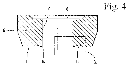
Fig. 4 an end brick according to the invention, shown in section;
Fig. 5 a detail V of the end brick according to Fig. 4, shown enlarged,
and
Fig. 6 a section of another version of an end brick according to the
invention.
Fig. 1 and Fig. 2 show a metallurgical vessel provided as an electric arc
furnace 1
with three implied electrodes 2 and a tap 3 for the emptying of the latter.
The elec-
tric arc furnace 1 is arranged here such that it can tilt so that the molten
metal pro-
duced can be let out without leaving any residue. This tap 3 with a tapping
channel
is 10 is contained in the refractory lining 1' in the bottom of the
furnace. The mode of
operation of this electric arc furnace 1 is not discussed any further because
this is
known.
In principle, instead of an electric arc furnace 1 a different metallurgical
vessel may
also be provided, for example a converter or a tilting furnace for non-ferrous
molten
metal.
The tap 3 is formed from a number of sleeve-like refractory individual
segments 5
lined up alongside one another and from an end brick 6 projecting from the
furnace
at the bottom and which is detachably fastened in a holding flange 7. The
individual
segments 5 and the end brick 6 are produced from a refractory material here,
for
example burnt or carbon-bonded magnesite or clay brick.

= CA 02958295 2017-02-15
- 5 -
In Fig. 3 this type of three-dimensional crown-like frozen steel slag layer 14
is
shown diagrammatically as an illustration, which on the known end bricks forms
on
the lower face side in every tapping process.
Before the start of a melting process the tapping channel 10 has to be closed
every
time so that it can be filled with filler sand. The closure is achieved by
means of a
closure device, the plate of which closes the tapping channel 10 at the
outlet. Per-
fect closure is not guaranteed if frozen steel slag layers produced in the
outlet re-
gion of the end brick 6 have built up and block the closure device.
In order to prevent this, the end brick according to the invention as shown in
Fig. 4
and Fig. 5 is provided with a slot 15 running round the outlet opening and
which
forms a sharp tear-off edge 16 in the face surface 11 of the end brick 6. This
pre-
vents rounding of the outlet surface from occurring here which encourages the
formation of frozen layers. Preferably, this tear-off edge 16 is formed
immediately
following the outlet opening 10.
As can be seen in Fig. 5, the slot 15, as seen in cross-section, is configured
such
that it has an inclined surface 18 that is inclined radially to the outside at
an angle
17 of between 5 and 20 , preferably 17 , relative to the face surface 11 of
the end
brick. The radial width 19 of the slot 15 is from 2 to 10 cm, preferably 5 cm.
The
slot 15 is rounded on the side 20 facing away from the tear-off edge 16. It
can be
milled either by pressing the end brick or subsequently in the finished end
brick.
The described geometry of the slot 15 has proven to be optimal if the tap is
work-
ing under normal operating conditions. However, it goes without saying that it
is

CA 02958295 2017-02-15
- 6 -
also possible within the framework of the invention to vary the slot profile
to a spe-
cific degree depending on the conditions of use if it guarantees the formation
of a
sharp tear-off edge without having any perceptible negative impact upon the
struc-
tural stability of the end brick.
According to Fig. 6, as a variation of an end brick, provision can be made to
in-
crease the effect of the slot 15 by providing in the face surface 11 of the
end brick
at least one additional slot 15a which surrounds the slot 15 and is preferably
formed with approximately the same profile.
The invention is sufficiently demonstrated by the above exemplary embodiments.
Needless to say, it could also be explained by other versions. Thus, a slot
with
barely a part circle could be assigned to the lower face surface of the end
brick.
The end brick with the slot would have to be fitted here by this holding
flange onto
the electric arc furnace such that upon tilting the furnace, approximately
half of the
end brick would be provided with the slot or the tear-off edge on which the
molten
mass flows out.

Representative Drawing
A single figure which represents the drawing illustrating the invention.
Administrative Status

2024-08-01:As part of the Next Generation Patents (NGP) transition, the Canadian Patents Database (CPD) now contains a more detailed Event History, which replicates the Event Log of our new back-office solution.

Please note that "Inactive:" events refers to events no longer in use in our new back-office solution.

For a clearer understanding of the status of the application/patent presented on this page, the site Disclaimer , as well as the definitions for Patent , Event History , Maintenance Fee  and Payment History  should be consulted.

Event History

Description Date
Application Not Reinstated by Deadline 2019-08-27
Time Limit for Reversal Expired 2019-08-27
Deemed Abandoned - Failure to Respond to Maintenance Fee Notice 2018-08-27
Inactive: Cover page published 2017-08-17
Inactive: First IPC assigned 2017-03-30
Inactive: IPC assigned 2017-03-30
Inactive: IPC removed 2017-03-30
Inactive: Notice - National entry - No RFE 2017-02-24
Application Received - PCT 2017-02-20
Inactive: IPC assigned 2017-02-20
National Entry Requirements Determined Compliant 2017-02-15
Application Published (Open to Public Inspection) 2016-03-24

Abandonment History

Abandonment Date Reason Reinstatement Date
2018-08-27

Maintenance Fee

The last payment was received on 2017-07-26

Note : If the full payment has not been received on or before the date indicated, a further fee may be required which may be one of the following

  • the reinstatement fee;
  • the late payment fee; or
  • additional fee to reverse deemed expiry.

Patent fees are adjusted on the 1st of January every year. The amounts above are the current amounts if received by December 31 of the current year.
Please refer to the CIPO Patent Fees web page to see all current fee amounts.

Fee History

Fee Type Anniversary Year Due Date Paid Date
Basic national fee - standard 2017-02-15
MF (application, 2nd anniv.) - standard 02 2017-08-25 2017-07-26
Owners on Record

Note: Records showing the ownership history in alphabetical order.

Current Owners on Record
REFRACTORY INTELLECTUAL PROPERTY GMBH & CO KG
Past Owners on Record
JOSSE BACHMAYER
KARL MICHAEL ZETTL
MARKUS HOCHEGGER
Past Owners that do not appear in the "Owners on Record" listing will appear in other documentation within the application.
Documents

To view selected files, please enter reCAPTCHA code :


To view images, click a link in the Document Description column (Temporarily unavailable). To download the documents, select one or more checkboxes in the first column and then click the "Download Selected in PDF format (Zip Archive)" or the "Download Selected as Single PDF" button.

List of published and non-published patent-specific documents on the CPD .

If you have any difficulty accessing content, you can call the Client Service Centre at 1-866-997-1936 or send them an e-mail at CIPO Client Service Centre.

({010=All Documents, 020=As Filed, 030=As Open to Public Inspection, 040=At Issuance, 050=Examination, 060=Incoming Correspondence, 070=Miscellaneous, 080=Outgoing Correspondence, 090=Payment})


Document
Description 
Date
(yyyy-mm-dd) 
Number of pages   Size of Image (KB) 
Description 2017-02-14 6 215
Abstract 2017-02-14 2 86
Drawings 2017-02-14 3 82
Claims 2017-02-14 3 66
Representative drawing 2017-02-14 1 7
Courtesy - Abandonment Letter (Maintenance Fee) 2018-10-08 1 174
Notice of National Entry 2017-02-23 1 193
Reminder of maintenance fee due 2017-04-25 1 111
International search report 2017-02-14 6 182
National entry request 2017-02-14 4 123
Patent cooperation treaty (PCT) 2017-02-14 1 67