Note: Descriptions are shown in the official language in which they were submitted.
RETRACTABLE AIR GASPER APPARATUS
Cross-Reference to Related Application(s)
[0001] This International PCT Patent Application relies for priority on
U.S.
Provisional Patent Application Serial No. 62/040,179, filed on August 21,
2014.
Field of the Invention
[0002] The present invention concerns a retractable air gasper
apparatus for
controlling the flow of air (velocity and direction) into a passenger
compartment of a vehicle.
More specifically, the present invention concerns an air gasper apparatus that
is provided so
that a passenger may adjust the flow of air into the cabin of an aircraft.
Description of the Related Art
[0003] In the prior art, there are numerous examples of air gaspers
that are provided
to satisfy any of a number of different environmental conditions.
[0004] Many of the known air gaspers present a nozzle that extends
outwardly from a
passenger service unit (PSU) overhead panel in which the air gasper is
disposed.
[0005] When the nozzle protrudes from the overhead panel, it is
conceivable that a
passenger may hit the nozzle when being seated or leaving his or her seat.
[0006] Separately, there are numerous sidewall panels that may need to
be opened to
access electrical wires and other system components therebehind. When these
sidewall
panels are opened, there is the possibility that the gasper nozzle may hit or
damage the
sidewall panel or the gasper itself
[0007] For several reasons, therefore, a need has developed for
improvements to air
gaspers that present a more minimal presence in the passenger compartment.
Summary of the Invention
[0008] The present invention addresses one or more of the deficiencies
noted with
respect to the prior art.
[0009] In one contemplated embodiment, the present invention provides
an air gasper
for a vehicle. The air gasper includes an air inlet, a first housing
disposable through a panel
in the vehicle, the first housing being connected to the air inlet, a second
housing disposed
within the first housing, an air outlet disposed within the second housing,
downstream of the
1
Date Recue/Date Received 2020-07-28
CA 02958405 2017-02-15
WO 2016/027183
PCT/IB2015/055696
air inlet, and a first mechanism connected between the first housing and the
second housing.
The first mechanism permits the second housing to be stowed within the first
housing in a
stowed position and also permits the second housing to extend outwardly from
the first
housing in a deployed position.
[0010] In a further contemplated embodiment, the air gasper includes a plug
associated with the air outlet to open and close the air outlet and a second
mechanism
connected to the second housing. The second mechanism permits the plug to open
and close
the air outlet.
[0011] In yet another contemplated embodiment, the air gasper also includes
a first
threaded region on an exterior surface of the first housing, a second threaded
region on an
interior surface of the first housing, a first ring engageable with the first
threaded region, and
a second ring engageable with the second threaded region. Here, the first ring
and the second
ring sandwich the panel therebetween to removably secure the first housing to
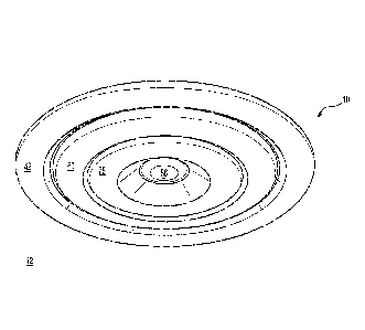
the panel.
[0012] It is contemplated that the first mechanism may include a first
biasing member
disposed between the first housing and the second housing to bias the second
housing in the
deployed position.
[0013] In addition, the first mechanism may include a locking mechanism to
lock the
first housing both in the deployed position and in the stowed position.
[0014] Still further, thc first mechanism may be push-button actuated.
[0015] With respect to another contemplated embodiment, the second
mechanism
may include a plug ring connected to the plug, a third threaded region on an
exterior surface
of the plug ring, and a fourth threaded region on an interior surface of the
second housing.
The third threaded region may engage the fourth threaded region so that
rotation of the
second housing moves the plug ring and plug with respect to the air outlet.
[0016] With respect to other embodiments of the air gasper of the present
invention,
the second housing may include a plug seat at the air outlet. The plug is
contemplated to
engage the plug seat when in the closed position, and the plug is contemplated
to be displaced
a distance from the plug seat when in the opened position.
[0017] A further embodiment of the air gasper of the present invention
contemplates
that a second biasing member is disposed between the first housing and the
plug ring to bias
the plug ring toward the closed position.
[0018] Separately, the air gasper of the present invention may include a
third housing
disposed between the first housing and the second housing. The third housing
is contemplated
2
CA 02958405 2017-02-15
WO 2016/027183
PCT/IB2015/055696
to be tiltable with respect to the first housing, thereby permitting angular
adjustment of the air
outlet.
[0019] In one contemplated embodiment, the air gasper includes a spherical
surface
surrounding the third housing. The first housing includes a spherical, inner
surface
complementary to the spherical surface surrounding the third housing.
[0020] In the embodiment where the air gasper includes a spherical surface
surrounding the third housing, the spherical, inner surface of the first
housing may be
provided with a stopper that limits a tilting angle of the tertiary housing.
[0021] It is contemplated that the first mechanism may include a first
biasing member
disposed between the second housing and the third housing to bias the second
housing in the
deployed position.
[0022] In addition, it is contemplated that the first mechanism also has a
locking
mechanism to lock the first housing both in the deployed position and in the
stowed position.
[0023] Still further, the first mechanism may be push-button actuated.
[0024] With respect to other embodiments of the present invention, the
second
mechanism in the air gasper may have a plug ring connected to the plug, a
third threaded
region on an exterior surface of the plug ring, and a fourth threaded region
on an interior
surface of the second housing. The third threaded region is contemplated to
engage the
fourth threaded region so that rotation of the second housing moves the plug
ring and plug
with respect to the air outlet.
[0025] As detailed herein, the second housing also may include a plug seat
at the air
outlet. If so, the plug is contemplated to engage the plug seat when in the
closed position and
be displaced a distance from the plug seat when in the opened position.
[0026] The air gasper of the present invention also may include a second
biasing
member disposed between the first housing and the plug ring to bias the plug
ring toward the
closed position.
[0027] It is contemplated that the air gasper may be used in an aircraft.
[0028] Furthermore, it is contemplated that the panel is an overhead panel
in an
aircraft cabin.
[0029] Further aspects of the present invention will be made apparent from
the
paragraphs that follow.
3
CA 02958405 2017-02-15
WO 2016/027183
PCT/IB2015/055696
Brief Description of the Drawing(s)
[0030] The present invention will now be described in connection with the
drawing
appended hereto, in which:
[0031] Fig. 1 is a cross-section of an interior of a cabin illustrating one
potential
location for placement of the air gasper of the present invention, also
illustrating one problem
to be solved by the present invention;
[0032] Fig. 2 is a cross-sectional side view of the air gasper of the
present invention,
showing the air gasper in a stowed, closed, and untilted position;
[0033] Fig. 3 is a perspective illustration of the air gasper of the
present invention,
providing an exterior detail of the air gasper in the stowed, closed, and
untilted position;
[0034] Fig. 4 is a cross-sectional side view of the air gasper of the
present invention,
showing the air gasper in the deployed, closed, and untilted position;
[0035] Fig. 5 is a perspective illustration of the air gasper of the
present invention,
providing an exterior detail of the air gasper in the deployed, closed, and
untilted position;
[0036] Fig. 6 is a cross-sectional side view of the air gasper of the
present invention,
showing the air gasper in the deployed, opened, and untilted position;
[0037] Fig. 7 is a perspective illustration of the air gasper of the
present invention,
providing an exterior detail of the air gasper in the deployed, opened, and
untilted position;
[0038] Fig. 8 is a cross-sectional side view of the air gasper of the
present invention,
showing the air gasper in the deployed, opened, and tilted position;
[0039] Fig. 9 is a perspective illustration of the air gasper of the
present invention,
providing an exterior detail of the air gasper in the deployed, opened, and
tilted position;
[0040] Fig. 10 is a perspective, cross-sectional illustration of the air
gasper of the
present invention, with the air gasper being shown in the deployed, opened,
untilted position;
[0041] Fig. 11 is a perspective, cross-sectional illustration of the air
gasper of the
present invention, with the air gasper being shown in the deployed, opened,
tilted position;
[0042] Fig. 12 is an exploded perspective illustration of elements of the
air gasper of
the present invention;
[0043] Fig. 13 is an exploded perspective illustration of elements of the
secondary
and tertiary housings of the air gasper of the present invention; and
[0044] Fig. 14 is an exploded perspective illustration of elements of the
secondary
housing of the air gasper of the present invention.
4
CA 02958405 2017-02-15
WO 2016/027183
PCT/IB2015/055696
Detailed Description of Embodiment(s) of the Invention
[0045] The present invention will now be described in connection with one
or more
embodiments thereof. The discussion of the embodiments is not intended to be
limiting of
the present invention. To the contrary, any discussion of embodiments is
intended to
exemplify the breadth and scope of the present invention. As should be
apparent to those
skilled in the art, variations and equivalents of the embodiment(s) described
herein may be
employed without departing from the scope of the present invention. Those
variations and
equivalents are intended to be encompassed by the scope of the present patent
application.
[0046] The present invention will now be discussed in the context of the
construction
of aspects of a cabin for an aircraft, such as a jet aircraft. While the
invention is discussed in
this context, the present invention is not intended to be limited solely to
the cabins for jet
aircraft. The present invention also is applicable to any other type of
aircraft, as should be
apparent to those skilled in the art. In addition, while discussed in the
context of aircraft, the
present invention may apply to vehicles other than aircraft, such as cars,
buses, and trains.
[0047] While the invention will be described in conjunction with specific
embodiments. It should be understood that the discussion of any one,
particular embodiment
is not intended to be limiting of the scope of the present invention. To the
contrary, the
specific, enumerated embodiments are intended to illustrate a wide variety of
alternatives,
modifications, and equivalents that should be apparent to those of ordinary
skill in the art.
The present invention is intended to encompass any such alternatives,
modifications, and
equivalents as if discussed herein.
[0048] In the following description, the same numerical references are
intended to
refer to similar elements. The re-use of reference numerals for different
embodiments of the
present invention is intended to simplify the discussion of the present
invention. It should not
be inferred, therefore, that the re-use of reference numbers is intended to
convey that the
associated structure is identical to any other described embodiment.
[0049] Although the preferred embodiments of the present invention as
illustrated in
the accompanying drawings comprise various components, and although the
preferred
embodiments of the system and corresponding parts of the present invention as
shown consist
of certain geometrical configurations as explained and illustrated herein, not
all of these
components and geometries are essential to the invention and, thus, should not
be taken in
their restrictive sense, i.e., should not he taken as to limit the scope of
the present invention.
[0050] It is to be understood, as should be apparent to a person skilled in
the art, that
other suitable components and cooperations therebetween, as well as other
suitable
CA 02958405 2017-02-15
WO 2016/027183
PCT/IB2015/055696
geometrical configurations, may be used for the air gasper according to the
present invention,
as will be briefly explained herein and as may be easily inferred therefrom by
a person skilled
in the art, without departing from the scope of the invention.
[0051] Additionally, it should be appreciated that positional descriptions
such as
"front," "rear," "right." "left," "top," "bottom," and the like are, unless
otherwise indicated,
to be taken in the context of the figures and should not be considered to be
limiting of the
present invention.
[0052] It will be appreciated that the present invention may be practiced
without all of
the specific details which are set forth herein below in order to provide a
thorough
understanding of the invention.
[0053] Fig. 1 illustrates the air gasper 10 (which may also be referred to
as an air
outlet, or air gasper outlet) of the present invention. This cross-sectional
view is provided to
illustrate one difficulty with aircraft construction that the present
invention seeks to
ameliorate.
[0054] With reference to Fig. 1, the air gasper 10 is position in a PSU
overhead panel
12. Typically, the PSU overhead panel 12 is located such that a passenger in a
seat may
reach above his or her head to adjust the flow of air from the air gasper 10
for personal
comfort.
[0055] An interior sidewall panel 14 is positioned immediately adjacent to
the PSU
overhead panel 12. The sidewall panel 14 covers one or more system components
(i.e.,
electrical wires 16 and the like) that lie between the sidewall panel 14 and
the fuselage wall
of the aircraft. The sidewall panel 14 is contemplated to swing inwardly into
the aircraft, in
the direction of the arrow 18. The top edge 20 of the sidewall panel 14,
therefore, sweeps
along a line 22 adjacent to the PSU overhead panel 12.
[0056] As may be immediately apparent, the air gasper 10 lies very close to
the line
22 swept by the top edge 20 of the sidewall panel 14. It is, therefore,
predictable that the
sidewall panel 14 might impact with the air gasper 10, thereby damaging the
sidewall panel
14 and/or the air gasper 10 when the sidewall panel 14 is opened. If damaged,
the air gasper
and/or the sidewall panel 14 may require replacement.
[0057] Still further, it is contemplated that a passenger might hit his or
her head on
the air gasper 10 when being seated or egressing from his or her seat. In such
an instance, the
passenger might hurt his or her head or damage the air gasper 10. In this
regard, the air
gasper 10 is spring-loaded (as discussed in greater detail below), thereby
permitting retraction
6
CA 02958405 2017-02-15
WO 2016/027183
PCT/1B2015/055696
of a portion of the air gasper 10, which serves to limit damage to the air
gasper 10 and/or the
passenger.
[0058] The air gasper 10 of the present invention is constructed to present
little or no
structure that protrudes from the PSU overhead panel 12 when the air gasper 10
is in a
stowed position. At least for this reason, the air gasper 10 of the present
invention is
constructed at least to avoid potential impact with the sidewall panel 14 when
the sidewall
panel 14 is opened and/or to minimize impact with a passenger. Other
advantages of the
construction of the air gasper 10 will be made apparent from the discussion
that follows.
[0059] The various components of the air gasper 10 are contemplated to be
made
from any material deemed suitable for the cab in of the aircraft. The air
gasper 10 may be
made from plastics, metals, metal alloys, composite materials, ceramics, or
any combination
of these materials, among others. The air gasper 10 of the present invention
is not considered
to be limited to any particular material or materials for its construction, as
should be apparent
to those skilled in the art.
[0060] Fig. 2 is a cross-sectional side view of the air gasper 10 according
to the
present invention.
[0061] The air gasper 10 is positioned in the PSU overhead panel 12 such
that the air
gasper 10 occupies a hole in the PSU overhead panel 12. The air gasper 10
includes a
primary housing 24 with an inlet 26 shown at the top end. The inlet 26 permits
air to enter
into the primary housing 24 so that the air may be directed in the cabin, as
selected by the
passenger. The inlet 26 may be connected to an air duct above the PSU overhead
panel 12, as
required or as desired.
[0062] The primary housing 24 includes a dome-shaped, upper section 28 that
transitions to a cylindrically-shaped, lower section 30. The exterior surface
of the dome-
shaped upper section 28 includes a threaded region 32. A ring 34 includes an
inner, threaded
surface 36 that threadedly engages the threaded region 32. The ring 34 is,
therefore,
adjustably mounted on the primary housing 24. When the air gasper 10 is
installed in the
PSU overhead panel 12, the ring 34 abuts against the upper surface 38 of the
PSU overhead
panel 12. The ring 34 permits the air gasper 10 to be adjustably mounted
against the PSU
overhead panel 12, with respect to the upper surface 38, as should be apparent
to those skilled
in the art.
[0063] To hold the air gasper 10 against the lower surface 40 of the PSU
overhead
panel 12, the air gasper 10 includes an annular ring 42. The annular ring 42
has a threaded
region 44 that engages a threaded region 46 on the interior surface of the
cylindrically-
7
CA 02958405 2017-02-15
WO 2016/027183
PCT/IB2015/055696
shaped, lower section 30 of the primary housing 24. A lip 48 abuts against the
lower surface
40 of the PSU overhead panel 12.
[0064] As should be apparent from Fig. 2. the PSU overhead panel 12 is
sandwiched
between the ring 34 and the lip 48 of the annular ring 42. Since both the ring
34 and the
annular ring 42 are threadedly attached to the primary housing 24, each ring
34, 42 separately
allows for adjustable positioning of the air gasper 10 with respect to the PSU
overhead panel
12. Moreover, by sandwiching the PSU overhead panel 12 between the ring 34 and
the
annular ring 42, the air gasper 10 is contemplated to be securely held in
position in the PSU
overhead panel 12.
[0065] The air gasper 10 includes a tertiary housing 50 located within the
primary
housing 24. The tertiary housing 50 has the shape of an inverted cup with a
central opening
52. The central opening 52 permits air to pass from the inlet 26, through the
tertiary housing
50. The tertiary housing 50 includes an upper section 54 and a lower section
56. The lower
section 56 includes an exterior, spherical surface 62 that abuts against an
inner spherical
surface 64 of the primary housing 24. The lower section 56 defines a tertiary
lip 60. When
the air gasper 10 is in the untilted position, as illustrated in Fig. 2, the
tertiary lip 60 is flush
with the annular ring 42.
[0066] The lower section 56 of the tertiary housing 50 has a spherical
shape due to
the exterior spherical surface 62. The spherical surface 62 of the tertiary
housing 50
compliments the inner, spherical surface 64 defined by the primary housing 24
and also the
inner, spherical surface 66 defined by the annular ring 42. As discussed in
greater detail
below, the spherical surface 62 facilitates tilting of the tertiary housing 50
within the primary
housing 24. As a result, the direction of the air flow from the air gasper 10
may be manually
adjusted by the passenger according to his or her personal preference.
[0067] As illustrated in Fig. 2, a seal 68 (such as an 0-ring or other
suitable sealing
member, whether circular or not) provides a seal between the spherical surface
62 and the
complimentary spherical surfaces 64, 66. The seal 68 discourages air from
being discharged
from the air gasper 10 by passing between the spherical surface 62 and the
primary housing
24 and/or the annular ring 42. In addition, the seal 68 establishes a proper
coefficient of
friction between the tertiary housing 50 and the primary housing 24, which is
helpful for the
turning of the twist knob 76, described in greater detail below.
[0068] A secondary housing 70 is disposed within the tertiary housing 50.
The
secondary housing 70 is a cup-shaped structure with a central opening 72. Air
passing
through the air gasper 10 is permitted to exit from the air gasper 10 through
the central
8
CA 02958405 2017-02-15
WO 2016/027183
PCT/IB2015/055696
opening 72. The secondary housing 70 includes a twisting knob 76 linked to a
fixed housing
74 via an annular insert 89. The bottom surface of the twisting knob 76
defines the secondary
lip 78. When the air gasper 10 is in the stowed position, the secondary lip 78
is flush with the
tertiary lip 60 and the primary lip 42, as illustrated.
[0069] A seal 80 (such as an 0-ring or other suitable sealing member,
whether
circular or not) is positioned between the outer wall 76 of the secondary
housing 70 and the
annular ring 58. The seal 80 discourages and/or prevents air from flowing
between the
secondary housing 70 and the annular ring 58.
[0070] The inner wall 74 of the secondary housing 70 includes a tapered
region 82
that extends inwardly from the inner wall 74 to define a sealing surface 84. A
plug 86
engages the sealing surface 84 (also referred to as a plug seal 84) when the
air gasper 10 is in
the closed position, as illustrated. In the closed position, the plug 86
engages the plug seal 84
and prevents air from being discharged through the central opening 72.
[0071] The secondary housing 70 is contemplated to be spring-loaded within
the
primary housing 24 such that the secondary housing 70 moves in the direction
of the arrows
94. In particular, a spring 88 is disposed between the upper section 54 of the
tertiary housing
50 and an upper surface 90 of the annular insert 89 that is disposed on top of
the secondary
housing 70. The spring 88 biases the secondary housing 70 in the direction of
the arrow 96.
[0072] The secondary housing 70 in the air gasper 10 is contemplated to be
actuated
by a pressing action on the secondary lip 78. When a person presses on the
secondary lip 78
in the direction of the arrow 98, it is contemplated that the secondary
housing 70 will he
unlocked from the stowed position illustrated in Fig. 2 and will transition to
the deployed
position illustrated in Fig. 3. To stow the secondary housing 70 into the
primary housing 24,
the passenger need only press again on the secondary lip 78 in the direction
of the arrow 98.
[0073] So that the secondary housing 70 may transition between the stowed
position
and the deployed position, a sliding pin 111 (which could be spring loaded to
return to its
nominal position), nested into the fixed housing 74, follows a heart shaped
cam track 113
inside the cam insert 112, which is nested into the lower section 56 of the
tertiary housing 50.
Together, the sliding pin 111, the cam path 113 and the spring 88 (among other
elements)
function as a locking mechanism that facilitates the transition of the
secondary housing 70
between the stowed position and the deployed position. The exact construction
of the spring-
actuated locking mechanism for the secondary housing 70 is not critical to the
present
invention. Any spring-actuated locking mechanism may be employed without
departing from
9
CA 02958405 2017-02-15
WO 2016/027183
PCT/IB2015/055696
the scope of the present invention. Separately, other locking mechanisms may
be employed,
whether spring-loaded or not, without departing from the scope of the present
invention.
[0074] In the upper, right-hand side of Fig. 2, an insert is provided
within dotted lines.
The insert is provided to illustrate the position of the sliding pin 111, cam
insert 112, and cam
path 113 discussed above. As should be apparent, the insert illustrates the
position of the
relevant elements for the stowed position of the secondary housing 70.
[0075] Fig. 3 provides a perspective illustration of a contemplated
exterior view of
the air gasper 10 in the stowed, closed, and unfitted position illustrated in
Fig. 2. As
illustrated, the primary lip 42, the tertiary lip 60 and the secondary lip 78
are flush with one
another and form a substantially planar surface parallel with the lower
surface 40 of the PSU
overhead panel 12.
[0076] Fig. 4 is a cross-sectional side view of the air gasper 10
illustrated in Fig. 2. In
this view, the air gasper 10 is illustrated in the deployed, closed, unfilled
position.
[0077] In the upper, right-hand side of Fig. 4, an insert is provided
within dotted lines.
The insert is provided to illustrate the position of the sliding pin 111, cam
insert 112, and cam
path 113 discussed above. As should be apparent, the insert illustrates the
position of the
relevant elements for the deployed position of the secondary housing 70.
[0078] As illustrated in Fig. 4, the secondary housing 70 may be rotated in
the
direction of the arrows 100 to open or close the air gasper 10. For operation
of the illustrated
air gasper 10, the plug 86 is connected to a plug ring 102 that includes
threads 104 on an
exterior side. The threads 104 engage threads 106 on the interior surface of
the fixed housing
74. The plug ring 102 moves in the direction of the arrows 94 in response to
rotation of the
twisting knob 76 in the direction of the arrows 100. Slots on the twisting
knob 76 push
against the ribs of the plug ring 102 to cause the plug ring 102 to move up
and down,
following the threads 104, 106. The plug 86 moves together with the plug ring
102.
[0079] For proper functioning of the circular ring 102, the secondary
housing 70
remains fixed to the tertiary housing 50 when the twisting knob 76 is turned.
This is achieved
by providing studs 99 on the fixed housing 74 and corresponding slots 101 on
the lower
section 56 of the tertiary housing 50. At the same time, the circular ring 68
prevents the
tertiary housing 50 from turning with respect to the primary housing 24, by
having a higher
coefficient of friction than the coefficient of friction required to turn the
twisting knob 76.
[0080] As indicated in connection with Fig. 4, the plug 86 is in the closed
position,
meaning that the plug 86 seats on the plug seat 84, thereby inhibiting the
flow of air through
the air gasper 10. However, after turning the twisting knob 76 in one of the
directions
CA 02958405 2017-02-15
WO 2016/027183
PCT/IB2015/055696
indicated by the arrows 100, the plug 86 may be unseated from the plug seat 84
to permit air
to flow through a gap 108 between the plug 86 and the plug seat 84, as
illustrated in Figure 6.
The gap 108 permits air to flow through the air gasper 10. The larger the gap
108, the greater
the air flow through the air gasper 108.
[0081] As may be apparent from the foregoing, the plug ring 102 and
secondary
housing 70 cooperate together (along with other elements of the air gasper 10)
and act as a
mechanism that permits the plug 86 to transition between the closed position
and the opened
position.
[0082] Fig. 5 is a perspective illustration, showing the air gasper 10 in
the deployed,
closed, untilted position, consistent with the illustration in Fig. 4. The
exterior surface of the
twisting knob 76 includes a knurled surface 115 to facilitate rotation of the
twisting knob 76
of the secondary housing 70 in the direction of the arrows 100. As should be
apparent, a
knurled surface 115 is not required to practice the present invention.
[0083] Fig. 6 is a cross-sectional side view of the air gasper 10 of the
present
invention. In this view, the air gasper 10 is illustrated in the deployed,
opened, and untilted
position. The gap 108 is visible in this view. As noted above, the gap 108
permits air to pass
through the air gasper 10.
[0084] Fig. 7 is a perspective, exterior view of one contemplated
embodiment of the
air gasper 10 of the present invention. Consistent with the illustration in
Fig. 6, the air gasper
is shown in the deployed, opened, untilted position.
[0085] Fig. 8 is a cross-sectional view of the air gasper 10 of the present
invention,
with the air gasper 10 being illustrated in the deployed, opened, tilted
position. Due to the
interaction between the spherical surface 62 of the tertiary housing 50 and
the spherical
surfaces 64, 66, the primary housing 24, the tertiary housing 50, and the
secondary housing
70 are permitted to tilt within the primary housing 24, as illustrated. The
tilting directions are
indicated by the arrows 114. A stopper feature 109 on the primary housing 24
limits the
tilting angle of the tertiary housing 50 so that secondary housing 70 and the
twisting knob 76
never touch nor damage the primary housing bezel 42.
[0086] Fig. 9 is an exterior perspective illustration of the air gasper 10
illustrated in
Fig. 8. Consistent with Fig. 8, the air gasper 10 is illustrated in the
deployed, opened, and
tilted position.
[0087] Fig. 10 is a perspective, cross-sectional illustration of the air
gasper 10 of the
present invention. The air gasper 10 is shown in the deployed, opened,
untilted position.
11
CA 02958405 2017-02-15
WO 2016/027183
PCT/IB2015/055696
[0088] Fig. 11 is a perspective, cross-sectional illustration of the air
gasper 10 of the
present invention. The air gasper 10 is shown in the deployed, opened, tilted
position.
[0089] Fig. 12 is an exploded perspective illustration of elements of the
air gasper 10
of the present invention.
[0090] Fig. 13 is an exploded perspective illustration of elements of the
secondary
and tertiary housings of the air gasper of the present invention.
[0091] Fig. 14 is an exploded perspective illustration of elements of the
secondary
housing of the air gasper of the present invention.
[0092] With respect to the various embodiments discussed above, one or more
of the
features from the emhodiments may be employed together without departing from
the scope
of the present invention.
[0093] As noted above, the embodiment(s) described herein are intended to
be
exemplary of the wide breadth of the present invention. Variations and
equivalents of the
described embodiment(s) are intended to be encompassed by the present
invention, as if
described herein.
12