Note: Descriptions are shown in the official language in which they were submitted.
CA 02958664 2017-02-23
Releasable Binding System
Cross-reference to Related Applications
[001] The following application claims benefit of U.S. Provisional Application
Nos.62299251,
filed 2/24/2016 and 62364534, filed 7/20/2016, each of which is hereby
incorporated by
reference in its entirety.
Background
[002] A number of sports or recreational activities require the attachment of
a user's body part
(frequently a foot) to a piece of equipment via a binding in order to allow
the user to control the
equipment. For example, snow skiing, snowboarding, waterskiing, wakeboarding,
and the like
all generally employ a binding that attaches a skier's foot (or shoe/boot) to
a board or ski.
However, unlike many other attachment mechanisms that are designed to detach
(or release) only
in response to one or more specific user inputs (pressing a button, moving the
object in a certain
way, etc.), ski bindings typically are designed to release in response to an
external stressor e.g.,
in the event of a fall so as to avoid or reduce significant injury. However,
mechanisms to
facilitate this "stress-based" release, can be challenging to design, as the
force and stresses
placed on the binding during normal use can be quite significant and an
unexpected/undesired
release during normal activity can also result in significant injury. Because
stress-based releases
typically come from unexpected and unpredictable angles, it is almost always
desirable for the
binding system to enable release in virtually any direction. Moreover,
different users with
different skill sets, levels of experience, or desired activities may have
significantly different
desired tolerance levels for the factors such as the force or torque that are
required to trigger a
stress-based release. (Consider for example, the varied release tolerances of
a beginning or
recreational water-skier, a beginning or recreational snow skier/boarder, a
professional slalom
skier (water or snow), a downhill racer, a mogul skier, or an aerialist.)
Furthermore, for obvious
reasons that tend to be consistent across a variety of sports equipment, is it
generally desirable
for the binding to be lightweight and have a low or small profile on the ski.
However most
current binding systems suffer from some combination of: limited degrees of
freedom of
releasability, excess weight, or contact distance between boot and ski.
Accordingly, there is a
need for a binding system that addresses each of these concerns.
1
CA 02958664 2017-02-23
C003] Accordingly, there is a great need for lightweight, low profile bindings
that have easily
adjustable tolerances and which enable release in virtually any number of
incremental rotations
and directions.
Summary
[004] The present disclosure provides a mechanism for releasably attaching a
first object to a
second object. According to various embodiments, the attachment mechanism
enables release in
a wide array of incremental directions and rotations. Moreover, various
embodiments provide
an attachment mechanism which enables the user to select a release threshold
wherein only a
force or torque applied above this threshold results in release. The mechanism
may also include
a user-operated release mechanism that may or may not be subject to the
threshold force or
torque requirements. As a specific example, the mechanism may be employed in a
binding
system that releasably attaches a boot or other wearable article to a ski or
other piece of sports
equipment.
Brief Description of the Drawings
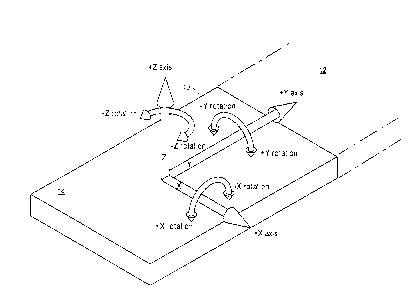
[005] Fig. 1 is a schematic illustration of the various rotational and
translational directions
discussed in the present disclosure.
[006] Fig. 2 is a schematic illustration of a mount according to an embodiment
of the present
disclosure.
[007] Fig. 3 is an exploded view of the mount in Fig. 2.
[008] Fig. 4 is a schematic top-view of an insert suitable for use with the
mount of Fig. 2.
[009] Fig. 5 is a schematic bottom-view of the insert of Fig. 4.
[010] Fig. 6 is an exploded view of the insert of Fig. 4.
[011] Fig. 7 is a top-view schematic illustration showing an insert mounted to
the sole of a boot
(shown in cutaway.)
[012] Fig. 8 is a bottom-view of the mounted insert of Fig. 7.
[013] Fig. 9 is an exploded view of the mounted insert Fig. 7.
[014] Fig. 10 is a top-view schematic illustration showing an insert
integrated with the sole of a
boot (shown in cutaway.)
[015] Fig. 11 is a bottom-view of the integrated insert of Fig. 10.
2
CA 02958664 2017-02-23
[016] Fig. 12 is an exploded view of the integrated insert of Fig. 10.
,
[017] Fig. 13 is a schematic illustration of an insert nested within and thus
secured to a mount.
[018] Fig. 14 demonstrates the sphere within a cylinder concept discussed in
the present
disclosure and illustrates how the mount and inserts described herein utilize
the sphere within a
cylinder concept.
[019] Fig. 15 shows an exemplary rotation within the sphere within a cylinder
concept.
[020] Fig. 16 shows an exemplary release within the sphere within a cylinder
concept.
[021] Fig. 17 is a top view of a first pin design according to the present
disclosure.
[022] Fig. 18 is a three-dimensional view of the pin of Fig. 17.
[023] Fig. 19 is a front-end view of the pin of Fig. 17.
[024] Fig. 20 is a side profile of the pin of Fig. 17.
[025] Fig. 21 is a schematic illustration of a pin locked within a vortex
channel, according to an
embodiment of the present disclosure.
[026] Fig. 22 is a three-dimensional illustration of the pin and vortex
channel configuration
shown in Fig. 21.
[027] Fig. 23A is a schematic illustration of a traditional pin in channel
configuration in the
locked position.
[028] Fig. 23B is a schematic illustration of an alternative channel geometry
according to an
embodiment of the present disclosure showing the pin in the locked position.
[029] Fig. 23C is a schematic illustration of a vortex channel geometry
according to yet another
embodiment of the present disclosure showing the pin in the locked position.
[030] Fig. 24A shows the pin and channel geometry of Fig. 23A as the pin is
releasing from the
channel.
[031] Fig. 24B shows the pin and channel geometry of Fig. 23B as the pin is
releasing from the
channel.
[032] Fig. 24C shows the pin and channel geometry of Fig. 23C as the pin is
releasing from the
channel.
[033] Fig. 25 is a schematic illustration of an embodiment according to
present disclosure
wherein multiple pins are controlled by the same tension release mechanism.
[034] Fig. 26 is a schematic illustration of an embodiment according to the
present disclosure
wherein multiple channels on the same mount body are differentially angled.
3
CA 02958664 2017-02-23
r0351 Fig. 27 is a schematic illustration of an insert having pins that are
angled to match the
channels in the mount body of Fig. 26.
[036] Fig. 28 is a schematic illustration of a +X rotation release in
progress.
[037] Fig. 29 is a schematic illustration of a -X rotation release in
progress.
[038] Fig. 30 is a schematic illustration of a -Y rotation release in
progress.
[039] Fig. 31 is a schematic illustration of a +Y rotation release in
progress.
[040] Fig. 32 is a schematic illustration of a +Z rotation release in
progress.
[041] Fig. 33 is a schematic illustration of a -Z rotation release in
progress.
[042] Fig. 34 is a schematic illustration of a composite +X/-Y/+Z rotation
release.
[043] Fig. 35 is another view of the composite +X/-Y/+Z rotation release shown
in Fig. 34.
[044] Fig. 36 is yet another view of the composite +X/-Y/+Z rotation release
shown in Fig. 34.
[045] Fig. 37 is a schematic illustration of an alternative embodiment of an
integrated
boot/release mechanism wherein the heel end of the boot extends past the rear
mount body.
[046] Fig. 38 is a schematic illustration of a +Z translation release.
Detailed Description
[047] In general, the present disclosure provides a mechanism for releasably
attaching a first
object to a second object. According to various embodiments, the attachment
mechanism enables
release in a wide array of incremental directions and rotations. Moreover,
various embodiments
provide an attachment mechanism which enables the user to select a release
threshold wherein
only a force or torque applied above this threshold results in release. Of
course, the mechanism
may also include a user-operated release mechanism that may or may not be
subject to the
threshold force or torque requirements.
[048] As a specific example, the mechanism may be employed in a binding system
that
releasably attaches a boot or other wearable article to a ski or other piece
of sports equipment.
Of course, it will be understood that while many of the specific examples are
directed towards a
boot/ski binding system, the mechanism itself may be applicable to a wide
variety of applications
wherein it is desirable for a second object to be able to release in a variety
of rotational directions
from a first object only after application of a pre-determined, and perhaps
user-defined amount
of force. While perhaps most easily understood in the context of ski bindings,
such applications
are not necessarily limited to sports equipment, but may include for example,
prosthetics, safety
4
CA 02958664 2017-02-23
riggings, and other applications where there is a desire for a range of
release direction options
=
and a preferred failure point.
[049] According to some embodiments the binding described herein may attach a
wearable
object to another object. For the purposes of the present disclosure a
wearable object may be any
object which is normally worn, mounted, or otherwise attached to a body
(including both humans
and animals) including, for example, without limitations, shoes, boots,
helmets, harnesses,
saddles, wrappings, etc. Because the present mechanism can perhaps most easily
be understood
in the context of skiing, the present disclosure, for the purposes of
simplicity will refer to a
"binding" that attaches a "skier's" "boot" to a "ski." However, it should be
understood that the
disclosure and invention should not be considered to be limited to only those
objects.
Accordingly, the as described attachment system can easily be used to attach
any first object to
any second object. Moreover, it will be understood that the user may not
necessarily be engaged
in the act of skiing and thus may not actually be a "skier."
[050] Because the present disclosure relies heavily on an understanding of how
and when the
binding releases as well as a unique sphere in cylinder design, understanding
of the invention
will be greatly enhanced by a general discussion of the nomenclature that is
used herein to
describe directions of translation and incremental rotations. There are three
orthogonal
directions (in three dimensions) and we name them relative to the ski as
follows:
X: The positive X direction points toward the skier's right, when the skier is
facing the
tip of the ski.
Y: The positive Y direction points toward the ski's tip.
Z: The positive Z direction points upward, normal to the plane of the ski.
[051] There are also three orthogonal rotations in three dimensions, and there
are many ways to
characterize them, including the order in which they are applied or,
equivalently, whether the
rotation planes are attached to the world or the body. However, for this
context we do not need
that level of exactness, and we just need to name the rotations for reference.
[052] In addition, the present disclosure refers to "incremental rotations."
In mathematics, this
is called a Lie Algebra, and in three dimensions there are six such rotations
¨ in each rotation
plane, we also differentiate by the direction of incremental rotation. We
choose to name
rotations according to the axis they rotate around, and use a right-handed
nomenclature: if your
right thumb is pointed down the axis, then your fingers curl in the direction
of positive rotation.
CA 02958664 2017-02-23
As a short-hand, we denote "positive-direction rotation around the X axis" as
simply "+X
rotation." Corresponding methodology is applied for the intended meanings of
¨X rotation, +Y
rotation, -Y rotation, +Z rotation, and ¨Z rotation. Fig. 1 shows these
coordinate axes and
rotation nomenclature conventions visually. Specifically, a portion of
ski/board 10 is shown
having a tip (distal) end 12 and a rear 14. The X, Y, and Z axes are shown
with labeled arrows,
as are the corresponding positive and negative rotations around these axes.
[053] According to a first embodiment, the binding system disclosed herein is
comprised of two
components, a mount, which is affixed to or integrated with the ski and an
insert which is affixed
to or integrated with the boot. Fig. 2 is a schematic illustration of an
exemplary embodiment of a
mount 20 and Fig. 3 is an exploded view of the same mount taken from a second
angle. Viewing
Figs. 2 and 3 together, it can be seen that mount 20 comprises first and
second mount bodies:
front mount body 22 and rear mount body 24. As depicted, mount bodies 22 and
24 are spaced
apart from each and are positioned so as to define a space 26 between them. As
shown, the
facing sides of each mount body have a concave portion which defines, for each
mount body, an
engagement surface. In Figs 2 and 3, the engagement surface in mount body 22
is labeled 28
while the engagement surface in mount body 24 is labeled 30. Moreover, each
mount body
engagement surface includes a socket. Front socket 40 in mount body 22 is
shown in Fig. 2,
while rear socket 42 in mount body 24 is shown in Fig. 3.
[054] As best seen in Fig. 3, the mount bodies 22 and 24 are secured to a
mount plate 32 via
upwardly directed bolts 31 and buried nuts 34. While it will be understood
that any suitable
securing mechanism could be employed, including alternate nut and bolt
configurations, glue,
interlocking components, snaplocks, etc., the depicted arrangement has the
benefit of providing
the mount bodies with a smooth upper surface. Since this surface will
eventually be positioned
under the skier's foot, a smooth surface is desirable both for function and
comfort. Of course as
stated above, other methods for securing the mount bodies to the mount plate
may be used and
such methods may or may not provide a smooth upper surface. Moreover, while
each mount
body is shown as being secured by two bolts, it should be understood that the
number and
specific placement of the bolts/securing method is not limited to the depicted
arrangement.
[055] Returning to simultaneous viewing of Figs. 2 and 3, it can be see that
in the depicted
embodiment, mount plate 32 can be secured to a ski (not depicted) via bolts
36. Again, it will be
understood that the number and specific placement of the bolts/securing method
is not limited to
6
CA 02958664 2017-02-23
the depicted arrangement. The mount plate enables the enforcement of a
consistent spatial
relationship between the mount bodies. This may be particularly desirable in
embodiments
wherein there is a high degree of expected flex in the ski during use.
However, it will also be
understood that rather than securing the mount bodies to a mount plate, as
shown in the depicted
embodiment, the mount bodies could be secured directly to the ski itself,
eliminating the need for
the mount plate. This may be advantageous when there is a strong desire to
reduce weight and
keep the binding closer to the ski.
[056] As stated above, the binding system comprises both the mount and an
insert. Fig. 4 is a
top view schematic illustration of an exemplary insert suitable for use with
the mount shown in
Figs. 2 and 3. Fig. 5 is a bottom view schematic illustration of the insert of
Fig. 4 while Fig. 6 is
an exploded side view of the same. As shown, insert 50 includes an undersole
52 having a toe
end 52 and a heel end 54. In the depicted embodiment, the toe end 52 is shown
as being wider
than the heel end, with the undersole body generally tapered from one end to
the other. It should
be understood, however, that other designs could be utilized including, but
not limited to, designs
which includes no taper at all (i.e. the toe and heel ends have the same
width, one side being
tapered to a greater degree than the other, and/or one side having a slight
inward curvature or
some other shape that may or may not mimic the general shape of a footprint.
As depicted, each
end 52, 54 is shown having a convex curvature which defines undersole
engagement surfaces 56,
and 58, respectively.
[057] Directing attention towards the toe end half of the undersole, seated
within and, under
some conditions, extending out of, front pin channel 60 (shown only in Fig. 6)
is a front pin 62.
Also seated within front pin channel 60 is front tension spring 64 (also shown
only in Fig. 6).
Seated within front dial hole 66 (seen best in Fig. 6) is front dialmate 68
and front tension dial
70. Pin 62, front tension spring 64, front dialmate 68, and front tension dial
70 work in concert
to produce a skier-operated front tension controlled release mechanism. For
the purposes of the
present disclosure, the term "pin" is not intended to imply or require any
specific shape or size,
but instead is used to refer to an extendable element of any shape or size
which can be received
by a socket and securely (and releasably) positioned within the socket via a
tensioning
mechanism.
[058] In the depicted embodiment, a rear tension controlled release mechanism
includes the
same elements at the heel end of the undersole. Namely, a rear pin 72 sits
within and, under
7
CA 02958664 2017-02-23
s'ome conditions, extends out of a rear pin channel (not shown). A rear
tension spring 74 is seated
within the rear pin channel. Seated within rear dial hole 76 is rear dialmate
78 and rear tension
dial 80.
[059] Whether in the front or rear of the binding, the tension controlled
release mechanisms
operate in substantially the same way. That is, the tension spring is operably
connected to the
dialmate and tension dial, which acts as a cam, and rotation of the tension
dial either slightly
extends or compresses the spring so as to increase or decrease the force
required to displace the
pin within its corresponding socket, thus allowing the user to make the
binding "tighter" or
"looser" according to his or her desired setting. It should be noted that the
depicted embodiment
enables the user to independently set the binding 'tightness" at the toe and
heel ends of the
binding. Of course, those of skill in the art will understand that there is a
wide variety of tension
control mechanisms that could be used in the present mechanism and that such
mechanisms may
or may not be controlled using the cam/dial system depicted. In general, in
embodiments which
employ the pin in socket configuration described herein, the tension control
mechanism should
control the amount of force required to displace the pin within the socket.
[060] According to some embodiments, the insert can be mounted to the bottom
of a boot, as
shown in Figs. 7-9. In the depicted embodiment, the undersole 52 is secured to
the bottom of the
boot 80 (depicted in cutaway) via bolts 82 and nuts 84. Fig. 9 is an exploded
view of the
arrangement. Alternatively, as shown in Figs. 10-12, a boot 90 could be
manufactured with an
integrated insert built as part of the sole. In this case, as shown best in
Fig. 11, the underside of
the boot's sole 92, includes a front Z channel 94 towards the toe end of the
boot, which is sized
and shaped to receive mount body 28 (not shown). Similarly, the underside of
the boot's sole
also includes a rear Z channel 96 towards the heel end of the boot, which is
sized and shaped to
receive mount body 30 (not shown). An exploded view of the integrated
embodiment is shown
in Fig. 12, which also shows the front and rear tension controlled release
mechanisms described
above.
[061] Fig. 37 shows an alternative embodiment of an integrated boot/release
mechanism
wherein the heel end of the boot 99 extends past rear mount body 30, resulting
in the presence of
a full rear Z channel 96.
[062] Fig. 13 shows the insert 50 securely installed within the mount
(variously and
equivalently referred to herein as the various components being in a "locked,"
"secured," or
8
CA 02958664 2017-02-23
"mounted" position). In this position the mount and insert act essentially as
a single solid piece
and enable the skier to translate his or her body movements through the boot
and binding to the
ski. While not shown in this drawing, it will be understood that in the locked
position, the front
and rear pins in the insert are in an extended position (i.e. pushed outwards
via the springs) and
are seated inside of the front and rear sockets in the mount bodies,
respectively. It will, of
course, be further understood that there will typically be at least some
degree of force applied to
the pin by the spring (or equivalent tensioning mechanism) when the pin is
secured in its
corresponding socket in order to maintain tension throughout the system and
keep the mount and
insert in the locked position. Though of course there may be some applications
or some
particularly loose binding settings where this is not desired and thus it
should be understood that
this is not necessarily a requirement of the presently described components
and tensioning
system. Additional details and embodiments are provided below in connection to
several
exemplary pin and socket geometries.
[063] In order to discuss how the binding release mechanism operates, greater
attention must
first be paid to the above-mentioned concave and convex curvatures of the
various engagement
surfaces. As stated above, one desired attribute of ski bindings is the
ability to release the boot
from the ski in a variety of directions while still allowing the binding to be
maintained under the
skier's foot. Moreover, an ideal binding would allow for a release in any
incremental rotation
and any combination thereof. Accordingly, one embodiment of the present
disclosure employs a
"sphere inside a cylinder" configuration wherein the two mount bodies and the
insert all share a
radius. In the context of these nested components, it will be understood that
the term "share a
radius" should be interpreted as meaning that the components that "share a
radius" have radial
edges that enabling nesting of one component within the other. Accordingly, it
will be
understood that the actual radius of the component that is nested within the
other component is
marginally smaller. Moreover, it should also be understood that the phrase
"share a radius" does
not necessarily require the presence of physical structure for the entire
circumference of the
shared radius, as this would essentially require a circular insert surrounded
entirely by a mount,
but rather that where the components are adjacent to each other, at least a
portion of the adjacent
surfaces have nested radial edges, as shown in the embodiments in the various
Figures. (Of
course, while not depicted, an embodiment with a circular insert is possible
and contemplated by
the present disclosure.)
9
CA 02958664 2017-02-23
[064] Figs. 14-16 depict the geometry behind this configuration. In Fig. 14,
sphere 100 sits
inside of hollow cylinder 102, whose inner radius 104 matches that of the
sphere. In the figure,
the cylinder is oriented so that its axis is in the Z direction. Because of
radial symmetry, the
sphere can be rotated about its center in any possible way, while remaining
wholly contained in
the cylinder. Additionally, the sphere can translate along the axis of the
cylinder. Accordingly,
it can be seen that the sphere can do any combination of any rotation and any
Z-direction
translation while still contained in the cylinder.
[065] Turning now to Figs. 15 and 16, it can be seen that the curvatures (i.e.
radial edges) of the
engagement surfaces of mount bodies 28 and 30 and insert 50 represent a subset
of the sphere
inside the cylinder geometry such that the mount bodies are contained within
the (same) hollow
cylinder, and the insert is contained within the sphere. The sphere-in-
cylinder analogy can be
further extended when even more parts are nested, such as in the integrated-
sole embodiment. In
this embodiment, the outer edge of the inner component (e.g. the front of the
front mount body)
is considered to be part of a surface of the sphere, and the inner edge of the
outer component
(e.g. the front of the front Z channel (shown in Fig. 12 at 98) is considered
to be part of a surface
of the cylinder. Fig. 15 shows the components in the secured position, while
Fig. 16 shows the
components in the released position. From this depiction, it can be seen that
release can occur in
any rotation and or Z-translation. Of course, in practice, the lower half of
all possible sphere-in-
cylinder release geometries are blocked by the presence of the ski, i.e., the
boot can only release
in the northern "hemisphere," of the sphere-in-cylinder geometry, as other
releases would
necessitate the boot passing through the ski. For the purposes of the present
disclosure the term
"releasability hemisphere" encompasses all six incremental rotations and +Z
translations shown
in Fig. 1 or any combination thereof, while not including those rotations or
translations that
would require the boot (or a portion of the boot) to pass through the ski.
[066] Further understanding of the release mechanism will now be aided by
discussion of
exemplary pin and socket geometries which facilitate operation of the herein
described ski
binding. For the purposes of discussion, the term "normal operation" is
intended to mean those
conditions when the skier wants the boot to remain attached to the ski ¨ i.e.
during normal skiing.
The term "release event" is intended to mean those conditions during which a
skier wants the
boot to detach from the ski, for example at impact during a fall and thus an
event which results in
sufficient torque or force being placed on the binding to overcome the user-
set tension setting
CA 02958664 2017-02-23
hich secures the boot to the ski. It will be understood of course, that
different skiers will have
different tolerances to conditions (a new skier may want the ski to release
with nearly any type of
torque or impact while a professional slalom skier would likely expect (and
want) a substantial
amount of torque to be placed on the skis during normal operation and thus
would only want the
ski to release in response to a high or very high degree of torque or force).
Accordingly, the
above-described tensioning system enables the individual skier to set the
amount of force that is
required to differentiate between what they would consider to be normal
operations and a release
event, and to change this setting as they see fit. Of course it will be
understood that the present
binding system could be provided with a single fixed tension setting (whether
or not this fixed
tension setting is initially dictated by the user) and that such embodiments
are contemplated by
the present disclosure.
[067] According to various embodiments, when the binding is secured for normal
operation,
each pin is forced into a corresponding socket by a tensioner, such as a
spring. Moreover, the
pin, pin channel, and corresponding sockets are designed such that when in the
locked position, a
shear force, acting in any direction between the mount bodies and the sole,
creates a force toward
the center along the pin channel. Under normal operation, the force of the
compressed spring is
greater than the shear force, so the pin does not retract and the side walls
of the socket prevent
the pin from moving. However, when a translated shear force exceeds the force
provided by the
spring (for example due to impact during a fall), the pin begins to retract
and/or move laterally
within the socket. This lateral motion is translated to the insert, leading to
release of the pin from
the socket and a corresponding release of the insert from the mount bodies.
(Of course it will be
understood that the direction of shear force and corresponding pin movement
and eventual
release can occur within in any rotational or translational directions thus
the reference to "lateral"
movement is not limited to simply movement in the Z-plane, but includes any of
the possible
coordinates in the in the releasability hemisphere.)
[068] Figs. 17-20 shown an example of a pin design wherein both the front edge
and distal
lateral surfaces of the pin head are rounded. Turning first to Figs. 17 and
18, it can be seen that
the distal end (or head) 110 of the pin is rounded both over the distal edge
as well as along a
portion of the lateral profile. In the depicted embodiment, the pin further
includes fins 112,
which help to maintain pin rigidity and channel 114, which is sized and shaped
to receive the
tension spring. Fig. 19 is a front end view of the pin in Figs. 17 and 18.
From this angle, it can
11
CA 02958664 2017-02-23
be understood that the top profile 116 of the pin head helps Y-rotation
releases to be smooth and
the wide based helps keep a solid connection between the pin and the pin
channel during normal
operation. Fig. 20 is a side profile of the pin in Figs. 17 and 18. From this
view, it can be
understood that the front profile 118 is rounded to assure that a relevant X-
rotation will push the
pin inwards against the force of the tension spring, enabling release.
Moreover, the depicted
front profile design enables Y-rotations to lift one side of the pin, which
also pushes the pin
inwards against the force of the tension spring, again enabling release.
[069] Fig. 23a is a schematic side illustration of a typical tensioned pin and
socket geometry.
In this configuration, a pin 25a with a rounded head is position with in a
scoop-shaped socket
27a. The pin is held in place (with the tip against the deepest portion of the
socket) via a spring
or other tensioning mechanism as described above.) As explained above, when a
translated shear
force exceeds the force provided by the spring (for example due to impact
during a fall), the pin
begins to move within the socket, as shown in Fig. 24a. It should be noted
that in this particular
configuration, the steepest tangent angle of lateral contact surfaces between
the pin and socket
remains the same or increases as the pin moves within the pocket. This can,
under certain
circumstances actually increase the holding force as the pin is displaced.
[070] However, according to some embodiments, it may be desirable to maximize
the
differential between the holding force under normal operation and holding
force during a release
event. Put another way, it may be desirable to ensure the binding is secure as
possible (and thus
won't release) during normal operation, but that release is as fast and easy
as possible during a
release event. Accordingly, in these embodiments, a pin and socket geometry
that increases the
holding force during displacement may be less desirable.
[071] Accordingly, the present disclosure provides alternate channel
geometries wherein the
steepest tangent angle of lateral contact surfaces between the pin and socket
occurs when the pin
is in the locked position within the socket, and the tangent angle of contact
surfaces decreases
when/as the pin is displaced, ensuring that displacement of the pin does not
increase and in some
cases actually decreases, the holding force.
[072] Figs. 23b and 24b show a pin and channel geometry wherein the channel is
shaped to
exactly match the external pin head geometry. As shown in Fig. 24b,
displacement of the pin
decreases the surface contact between the pin and the channel, thereby
decreasing the holding
force as the pin is displaced.
12
CA 02958664 2017-02-23
1073] An alternative socket geometry, referred to herein as a "vortex socket"
is depicted in
Figs. 21, 22, 23c and 24c. The vortex socket results in the steepest angle of
lateral contact
surfaces when the pin is positioned within the socket and decreases the angle
of lateral contact
surfaces when/as the pin is displaced, ensuring that displacement of the pin
does not increase and
in some cases actually decreases, the holding force. This geometry takes
advantage of the
mathematical principle that at a contact angle of "0" (by which is meant a
contact angle
tangential to pin head), there is no resistance to lateral movement. At a
contact angle of "90"
there is no force that is translated down the pin. In between, there is a
continuum of how much
lateral force is translated into down-pin force.
In the vortex socket embodiment, instead of
simply mimicking the external geometry of the pin head, the walls of the
socket create a socket
pocket in which the pin head sits during normal operation and then sweep
outwards as they
extend towards the opening, away from the lateral sides of pinhead. The socket
pocket acts to
self-center the pin in the center of the socket during normal operation, while
the outswept walls
encourage release after displacement in response to a release event. This is
because, as the pin is
displaced, the pin moves into an increasingly more shallow portion of the
socket, moving the
contact point on the pin towards the distal tip, resulting in a shallower
contact angle, which
means that less lateral force is required to displace the pin in that
direction. (Compare, for
example, Figs. 23c and 24c.)
[074] It is noted that according to various embodiments, the sockets are
entirely passive (i.e.
include no moving parts) and, in fact, as depicted, the entire mount can
easily be manufactured to
include no moving parts. In these embodiments, any moving parts are contained
within the
insert. Accordingly, in embodiments wherein the mount is attached to the ski
and the insert is
attached to (or an integrated component of) the boot, the components attached
to the ski can be
small and light weight, reducing the weight of the ski, which may be
significant when skis are
carried. Small components on the ski also allows maximum contact surface of
the boot to the ski
in applications where the feet need to be close together and thus some or all
of the mount lies
underneath the boot, such as on a slalom water ski.
[075] Of course while the depicted embodiments have shown only a single pin
and socket
tension controlled release mechanism at each end of the insert, it will be
understood that any
number of tension controlled release mechanisms may be used, as space and need
dictate or
allow. It will be understood that some embodiments of the presently described
binding may be
13
CA 02958664 2017-02-23
. ,
better situated for 2, 3, 4, 5, or more tension controlled release mechanisms.
For example, mono-
skis, sit-skis and other adaptive equipment may require a larger ski and/or
greater area of contact
between the equipment that is strapped (or otherwise connected) to the skier
and the ski. In this
case, it may be preferable to increase the number of tension controlled
release mechanisms to
create a suitable binding.
[076] When multiple pins extend out of the same end of the boot or undersole,
special
asymmetric head geometries may be used. Most of the same considerations that
relate to a single
pin (per end) still apply. In addition, the individual pins may be asymmetric
to the left and right
of their long axis, but the pins may be approximately symmetric to each other
about the YZ
plane. For example, if the inward-facing surfaces are steeper than the outward-
facing surfaces,
then when a pin enters a socket that is not the intended or correct socket, it
will both not
penetrate deeply and be depressed fully flush with relatively little around Z
torque. This helps to
prevent a pin from sticking in an incorrect socket, either when entering the
system or during a Z-
rotation release.
[077] Fig. 25 provides an embodiment wherein two pins are utilized within each
tension
controlled release mechanism. To aid visualization, the components are only
shown present on
one end, while empty channels are shown at the other end. Furthermore, while
some
components, such as the dials, dialmates, and screws, are not shown in this
illustration, their
absence does not imply they could not be used. In the depicted embodiment, two
pins 140a,
140b, at each end of undersole 142 are radially seated within pin channels
144a and 144b,
respectively. The proximate end of each pin is operably connected to a plunger
146, which
receives tension spring 148. As shown, each pin then has its own channel that
intersects with a
main plunger channel 147, enabling each pin to have a contact surface with the
plunger. In
general, the pin channel sliding axes are not parallel to one another or to
the plunger channel
sliding axis. In this configuration, when one pin is depressed, it depresses
the plunger and
tensioner. Thus, the tensioner no longer acts on the other pin(s) and
therefore they can depress
with very little force. This may help to allow a clean release. Note that the
pin/plunger contact
point may slide laterally when a pin is depressed, because the pin channel
axis of sliding may not
be parallel to the plunger channel axis of sliding. This same mechanism could
also be used with
a single pin, to allow the tensioner and the pin to point along different
axes.
14
CA 02958664 2017-02-23
1078] Of course it will be understood that the radial arrangement of the pins
as depicted in Fig.
25 is not required. For example, each pin could have its own independent
tension controlled
release mechanism, which could be desirable for a skier who wants even finer
control over the
shear force required for release. However, the arrangement depicted in Fig. 25
has the advantage
of allowing the skier to easily set the same tension for both pins and,
perhaps more importantly,
ensures simultaneous release of the pins.
[079] It will be appreciated that some multi-pin embodiments, such as the
radial arrangement
described above, prevent a pin from inadvertently entering the wrong hole and
misaligning the
releasable undersole relative to the mount bodies. Another option to prevent
inadvertent
mismatching is to choose pin/socket cross-sections that do not allow a pin to
enter to a non-
matching socket. For example, a square pin and a round pin, with appropriate
sizes, will not fit
into each other's sockets. Of course it will be appreciated that many other
non-matching cross-
sections are possible.
[080] A variation on the non-matching cross-sections is to mount the bodies of
the pins at
different out-of-plane angles. This type of pin geometry is shown in Figs. 26
and 27 wherein pin
150a (Fig. 27) is positioned at a first angle and fits into similarly angled
socket 150b (Fig. 28)
and pin 152a (Fig. 27 is positioned at a second angle and fits into similarly
angled socket 152b.
A similar system may be used with any number of pins by selecting different
angles (including
0).
[081] It should be noted that while many of the depicted embodiments show the
sliding axis of
the pin to be aligned radially, this is not a requirement. Moreover, it will
be understood that
various combinations of any of the above geometries are also possible. As a
non-limiting
example, a particular binding may employ the single pin geometry shown in Fig.
13 at the heel
end and the double pin geometry shown in Fig. 25 at the toe end, or vice
versa.
[082] Of course it will be understood that the direction that each pin
protrudes does not need to
be generally away from the foot, but can be toward the interior instead. In
this case, the
geometric analogy of the socket and sole may be swapped: the socket where it
connects to the
pin is cut from a sphere, and the sole where the pin exits is cut from a
cylinder. Moreover, in an
embodiment where all of the pins point inward and approximately radially, a
single shared
mount piece that has sockets for each of the pins could be employed. As an
example, this mount
piece might have a circular cross-section and be cut from a sphere, and placed
near the center of
CA 02958664 2017-02-23
the skier's foot, while the insert may comprise one or two portions cut from
the sphere's
surrounding cylinder, positioned to both receive and position the shared mount
piece.
[083] Note that, in practice, a thin part that is cut by a sphere is almost
indistinguishable from
one cut from a cylinder, because the cosine of a small angle is nearly 1Ø
Therefore, various
alternative embodiments could employ any combination sphere- or cylinder-
derived segments or
subsets thereof.
[084] As stated above, the sphere in cylinder geometry of the presently
described binding
enables infinitely incremental releases throughout an entire releasability
hemisphere. These
releases are demonstrated in Figs. 28-36. Fig. 28 shows a +X rotation release
in progress and
Fig. 29 shows a -X rotation release in progress. Fig. 30 shows a -Y rotation
release in progress
while Fig. 31 shows a +Y rotation release in progress. Figs. 32 and 33 show a
+Z and -Z rotation
release in progress, respectively. Figs. 34-36 show three rotated views of a
composite +X/-Y/+Z
rotation release. Fig. 38 shows a +Z translation release.
[085] It should be noted that when in the locked position, the circle in
cylinder geometry has
the added feature of providing a nearly seamless contact surface for the
skier's boot/foot. For
maximum performance and control, it is typically desirable to have as much
contact as possible
both between the insert and the mount and between the skier's boot and the
ski. As shown, the
concave curvature of each mount body (28, 30) matches the convex curvature of
the toe and heel
ends of the insert, so that the engagement surfaces of the mount bodies are
smoothly aligned with
the engagement surfaces of the insert with minimal gapping between the
components. This
provides the skier with a smooth, comfortable, and solid feeling footing as
well as maximum
control as the skier's movements are easily and directly translated to the
ski.
[086] Of course it should be realized that any angle which enables release,
can also be
employed in the reverse for engagement. Accordingly, the same rotations (but
in the opposite
direction) shown in Figs. 28-36, and 38 can be used to "snap" the insert pins
into their
corresponding sockets, so long as a mechanism is provided to enable depression
of the pin to
make it flush with the undersole body prior to it snapping into the
corresponding socket. For
example, the insert can be placed flat but rotated in Z and then rotated
"inwards" (i.e. in the
direction opposite from the original rotation). In this case, Figures 32 and
33 would show the
insert just prior to the pins snapping into their corresponding sockets. In
this case, flat sections 29
on the mount bodies then push the pin into the insert as the insert is rotated
inwards. When the
16
CA 02958664 2017-02-23
p' in reaches the socket, the pin pushes outwards and snaps into the socket
due to force created by
a tensioner, such as the front and rear tensioner springs shown in Fig. 6. The
boot is then
mounted on the ski via the binding. Alternatively, a shoe-horn-like approach
could be employed.
According to a not depicted alternative embodiment, the upper surface of the
mount bodies may
be ramped or incorporate a ramp that allows downwards movement of the pin
against the upper
surface of the mount body to depress the pin until it reaches the socket and
snaps into place,
enabling rotations such as those shown in Figs 18-31, 34-36, and 38 to secure
the insert to the
mount.
[087] As a whole, Figs. 28-36 and 38 show how the insert is designed to move
relative to the
mount bodies and how the unique sphere in cylinder geometry enables this
movement.
However, it will be understood that because the insert needs to be able to
slide into place, the
presence of sharp corners could hinder sliding and thus release or engagement
and thus the
corners could be slanted or rounded as shown in the various figures.
[088] According to various embodiments, it may be desirable for the skier to
be able to adjust
the binding relative to the ski without actually redrilling holes or
reattaching the mount and
without changing any of the release characteristics of the binding. To
accommodate this, the
holes in the mount plate through which the bolts attach to ski, can be slotted
in the Y direction.
When the mount bolts are loose, this allows the plate to move in Y.
[089] According to some embodiments, a subset of these slotted holes can have
teeth placed on
either or both sides of the slot, in any combination of embedded in or
protruding out from the
mount plate. In this configuration, each tooth could run along the X axis a
short distance.
According to this embodiment, a matching, separate bolt holder could also be
provided, which
also has matching teeth. The teeth may be any reasonable periodic pattern,
such as triangle wave
(aka saw tooth), sinusoid, or alternating half-circles. The teeth would allow
a relatively fine
selectin of Y position for the boot. But when the teeth are engaged and the
bolt is tight, it
becomes almost impossible for the mounted system to move in the Y direction.
This assures the
mount remains where it was intended to be.
[090] As a further embodiment, teeth that are 180 out of phase with each
other can be placed
on either side of a slot. The bolt holder could also have this paired-out-of-
phase pattern. This
would allow the bolt to be positioned with a resolution of half the spacing of
the teeth, by
choosing whether to take the odd or even positions by rotating the bolt holder
180 degrees.
17
CA 02958664 2017-02-23
[091] Alternatively or additionally, it may be desirable for the sole of the
boot to be positioned
on the ski rotated around the linear axis. For example, in some of the
relevant disciplines,
notably slalom-waterskiing, wakeboarding, and snowboarding, it is often
desirable to adjust the
Z-rotation (sometimes called pivot) of the mounted position of a boot. To
facilitate that, the
mount is rotated in the plane of the ski. Note that the axis of this rotation
is not necessarily the
center of the virtual sphere and cylinder of the release mechanism. Further
note that this rotation
has no impact on the mounting or release characteristics, because the inserts
will be rotated to
match when installed.
[092] To produce a rotatable mount (i.e. one wherein the specific Z-rotation
of the mounts can
be selected by the skier), arced slots that all share the same axis of
rotation can be used. If a
mount plate is used, the holes for the mount plate can be slotted.
Alternatively, whether or not a
mount plate is used, the bolt holes in the mount bodies could be slotted.
[093] In either case, teeth can be used in a manner similar to that described
above, except that
the teeth are in a radial pattern ¨ i.e. the teeth all run toward the shared
center. As before, the
teeth may be embedded in and/or raised above the mount plate, and their radial
profile may be
any reasonable periodic function. Matching teeth are then cut in the bottom of
each socket.
Note that these socket pieces do not necessarily have identical tooth patterns
to each other, due to
the release center being different from the mount-rotation center.
[094] Moreover, it should be noted that in an activity like snowboarding,
where both feet are
attached to the same board, this embodiment would easily enable the skier to
specifically and
separately adjust the specific Z-rotation angle for each foot.
[095] Alternatively or additionally, it may be desirable for the sole of the
boot to be non-
coplanar with the ski. For example, it may be desired to set the boot with an
X rotation
(sometimes called pitch) or with a Y rotation (sometimes called cant). For
small amounts of
such rotations, a wedge plate placed underneath the mount plate suffices, with
mount holes
matching the mount plate. To allow some choice of the rotations, plates of
various angles can be
provided, and then stacked. For example, a 2-degree X rotation plate and a 1-
degree Y rotation
plate could both be placed under the mount plate. Again, this has the
advantage of making no
change to the release characteristics. If a larger amount of X or Y rotation
is desired, then a
version of the mount plate may be used that is shaped like a wedge but has
holes oriented in the
18
CA 02958664 2017-02-23
direction. Alternatively, material inside the boot can create the desired
orientation of shin to
ski.
[096] Finally, while substantial attention has been paid to release of the
boot from the ski due to
shear force (i.e. in the event of a crash), it is understood that it may be
desirable for the skier to
release the boot from the ski voluntarily ¨ for example, when a run has ended.
According to a
first embodiment, to voluntarily detach the skier's foot from the ski, the
skier can simply loosen
the boot (e.g. buckles or laces) and remove his or her foot from the boot. In
this case, no actual
voluntary release mechanism is integrated into the system. This is quite
suitable and often
employed for water sport bindings, but may not be desirable for snow sports.
[097] Accordingly, some embodiments may include a voluntary release mechanism.
An
exemplary mechanism might be or include an integrated lever that forces
release. For example, a
longer lever outside the sole could be attached via an axis inside the sole,
to a shorter lever. This
creates the mechanical advantage to force the mechanism to release with a
relatively small force
on the external lever. Alternatively, the mechanism could include a similar
lever that either
pushes on the pin or de-tensions the tensioner, allowing the boot to be easily
released with a
slight lift.
[098] Under no circumstances may the patent be interpreted to be limited to
the specific
examples or embodiments or methods specifically disclosed herein. Under no
circumstances may
the patent be interpreted to be limited by any statement made by any Examiner
or any other
official or employee of the Patent and Trademark Office unless such statement
is specifically and
without qualification or reservation expressly adopted in a responsive writing
by Applicants.
[099] The terms and expressions that have been employed are used as terms of
description and
not of limitation, and there is no intent in the use of such terms and
expressions to exclude any
equivalent of the features shown and described or portions thereof, but it is
recognized that
various modifications are possible within the scope of the invention as
claimed. Thus, it will be
understood that although the present invention has been specifically disclosed
by preferred
embodiments and optional features, modification and variation of the concepts
herein disclosed
may be resorted to by those skilled in the art, and that such modifications
and variations are
considered to be within the scope of this invention as defined by the appended
claims.
19