Note: Descriptions are shown in the official language in which they were submitted.
CA 02958709 2017-02-20
WO 2016/038251
PCT/F12015/050592
1
HEATING OF HYDRAULIC DIGESTERS
This invention relates to a method of producing chemical pulp in an
impregnation
stage and a cooking stage, using a hydraulic digester, especially a single-
vessel hy-
draulic digester. The invention relates also to a digester system and to a
steam injec-
tor.
Continuous digesters are widely used to produce chemical pulp. There are
essential-
ly two main types of continuous digesters: the hydraulic digester and the
vapor-
phase digester. A hydraulic digester is a pressure-resistant vessel which is
com-
pletely filled with comminuted cellulosic fibrous material and liquid; any
introduction
or removal of liquid from the vessel affects the typically super-atmospheric
pressure
within the vessel. A vapor-phase digester is not completely filled with liquid
but in-
cludes a section at the top containing super-atmospheric steam. Since this gas
zone
is compressible compared to the liquid zone below it, the pressure within a
vapor-
phase digester is typically determined by the pressure of the gas present at
the top
of the digester. The reaction of pulping chemicals with comminuted cellulosic
fibrous
material to produce a chemical pulp requires temperatures ranging between 140-
180
C. Since at atmospheric conditions the aqueous chemicals used to treat the
materi-
al would boil at such temperatures, commercial chemical pulping is typically
per-
formed in a pressure-resistant vessel under pressures of at least about 5 bars
gauge.
One principal distinction between the method of operation of these two types
of di-
gesters is the way the contents of the digesters are heated to the desired 140-
180
C. In the vapor-phase digester, the chips are typically heated by exposing the
chips
to steam. This steam heating is typically performed as the chips are
introduced to the
steam-filled zone at the top of the digester. In the hydraulic digester, the
slurry of
comminuted cellulosic fibrous material, typically wood chips, and cooking
liquor is
typically heated by means of heated liquid circulations, i e. one or more
recirculation
loops. Liquid is typically removed from the digester, for example, by using an
annular
screen assembly and pump, heated with steam by means of an indirect heat ex-
changer, and re-introduced to the material in the vessel using a centrally
located
pipe. It has not been possible to add direct steam to the top of the hydraulic
digester
because the steam condensing into liquor would have caused hammering and in
the
worse it could have caused cracks to the digester shell. In some cases a steam
line
has been connected to the top of the hydraulic digester, but purpose of this
steam
CA 02958709 2017-02-20
WO 2016/038251
PCT/F12015/050592
2
has been to push the digester empty of chips and liquor before the shutdown,
not to
use it for heating during normal operation.
Furthermore, chips are introduced to the digesters using different mechanical
devic-
es. Wood chips, or other comminuted cellulosic fibrous material, are typically
fed to
the inlet of a continuous digester using a separate feed system. The feed
system
typically includes equipment for de-aerating, heating, pressurizing, and
introducing
cooking liquor to the chips before transferring a slurry of chips and liquor
to the di-
gester. In the case of the hydraulic digester, this slurry of chips and liquor
is intro-
duced in a downward-directed screw-type conveyor at the top of the digester,
known
in the art as a "top separator".
The digester chip feed systems can be divided into two classes: Systems which
have
only atmospheric steaming to heat the chips and remove air from the chips, and
sys-
tems which have both atmospheric and pressurized steaming. If there is only
atmos-
pheric steaming the temperature level at feed system is typically about 100
C. If
there is also pressurized steaming, where the pressure is typically 0.7 to 1.5
bar
higher than the atmospheric pressure, the temperature level is typically from
115 to
125 C. There is no additional heating between the feed system and the top of
a sin-
gle-vessel hydraulic digester and the temperature in the impregnation zone at
the top
is at the same level as in the feed system. Cooking temperature in the cooking
zone
is typically between 140 C and 180 C. So there is a large temperature
difference
between the impregnation zone temperature at the top of the single-vessel
hydraulic
digester and the cooking zone. Due to the large temperature difference it can
be dif-
ficult to heat the chips and liquor evenly by the cooking circulations. If the
heating is
not even some chips are not cooked as much as the others and the pulp quality
is
uneven and there can be a lot of uncooked material in the pulp. The bigger the
tem-
perature difference between the impregnation zone in the top and the cooking
zone
is the more difficult it is to reach an even heating result. Hot liquor
density is lower
than cold liquor density. If the density difference between the cooking zone
hot liq-
uors and impregnation zone cool liquors is too large, the hot liquor starts to
channel
to the top of the digester and cool liquors start to channel to the cooking
zone caus-
ing severe disturbances for the cooking process. So it would be advantageous
to be
able to increase the impregnation zone temperature of the hydraulic digester,
such
as a single-vessel hydraulic digester, especially in the cases when there is
only at-
mospheric steaming in the feed system and the temperature difference is high.
CA 02958709 2017-02-20
WO 2016/038251
PCT/F12015/050592
3
W094/23120 describes a method in which steamed chips entrained in relatively
cool
liquor (at about 116 C) are fed toward the top of a digester. The cool liquor
is sepa-
rated from the chips in a stand-alone separator/liquid exchanger (such as an
inverted
top separator) externally of the digester and replaced with hot cooking liquor
(e.g. at
143 C). The chips entrained in cooking liquor at cooking temperature are fed
to the
top of the digester. This process requires a free-standing liquid exchanger.
Further-
more, it does not solve the problem caused by a high temperature difference in
a
single-vessel digester having an impregnation zone. A similar method is
disclosed in
US5658428, but the cool liquor is replaced with hot impregnation liquor in a
liquid
exchanger externally of the digester
An object of the new method is to provide an improved method for continuous
cook-
ing in a hydraulic digester, such as a single-vessel hydraulic digester, so
that a sus-
pension of chips can be evenly heated in the digester.
For achieving these objectives the present invention relates to a method of
produc-
ing chemical pulp in an impregnation stage and a cooking stage, using a
hydraulic
digester having a top separator, a level of chips and a liquid phase above the
level of
chips, said method comprising the features of claim 1. The top separator is a
sol-
id/liquid separator at the top of the digester. It has a cylindrical screen
surrounding a
screw conveyor.
The invention relates also to a digester system according to claim 5 and to a
steam
injector according to claim 9. Preferred embodiments of the invention are
disclosed
in the dependent claims.
Surprisingly it has been found that direct steam can be fed safely to the
liquor phase
above the chip level at the top of the single-vessel hydraulic digester by
using one or
more steam injectors. In these injectors the steam flow is divided into small
bubbles
and the condensing of the small bubbles does not cause hammering or risks of
breaking the hydraulically full cooking vessel.
In the new method direct steam is added to the liquor phase above the chip
level at
the top of the single-vessel hydraulic digester via one or more steam
injectors to in-
crease a temperature of the impregnation zone. A temperature increase can be
from
1 to 40 C, preferably from 5 to 30 C. Temperature increase should be
significant to
achieve considerable benefits. On the other hand, too high an increase may not
be
CA 02958709 2017-02-20
WO 2016/038251
PCT/F12015/050592
4
good because it is more economical to heat with indirect steam in the liquor
circula-
tion heaters of the digester and collect the steam condensate than with direct
steam.
In addition, excessively high impregnation temperature might cause adverse
effects
on the pulp quality. It is especially advantageous to use the new method when
there
is no pressurized steaming stage or only a slightly pressurized steaming stage
(the
pressure below 0.5 bar (g)) in the chip feed system of the hydraulic digester
and the
temperature of the chip slurry is 110 C or below. This means that the
temperature of
the impregnation zone would be less than about 110 C without additional
heating in
accordance with the new method.
Steam is fed through a steam injector which is arranged in a wall of the top
of the
digester. The steam injector comprises a tube which extends to the interior of
the
digester and which is connected to a steam source located outside the
digester. The
length of the tube inside the digester is 150 -2500 millimeters (mm),
typically 200-
600 mm. The tube has a plurality of openings for discharging steam to the
liquor
phase above the chip level. Typically the openings are circular small holes
having a
diameter of 0.1-15 millimeters (mm), preferably 1.5-5.0 mm. The holes can be
con-
figured, typically, as circular holes, but also as gaps or slots. The term
"hole" should
therefore not be given any restrictive meaning, but should cover all through
open-
ings, slots, etc., regardless of shape.
The openings, typically hundreds of small holes, are distributed along the
circumfer-
ence and the length of the tube wall as a continuous zone or as separate
zones. The
separate zones may be disposed spaced apart along the length and circumference
of the tube. The number of the holes depends on the steam flow required for
heating
the chip suspension, and thus the zone or zones can cover adequate portion(s)
of
the tube wall. Some portions of the tube wall may be unperforated. For
instance, the
tube end and/or the portion closest to the digester wall may be unperforated,
where-
as the portion therebetween is perforated partially or entirely.
There may be more than one tubes (injectors) disposed along the circumference
of
the digester wall so that the tubes may be equally or unequally spaced apart
from
each other. The distance between the tubes may depend e.g. on the construction
of
the top part of the digester.
CA 02958709 2017-02-20
WO 2016/038251
PCT/F12015/050592
According to one aspect of the new system the steam flow from steam openings
may
be directed radially and/or circumferentially in the digester. The steam flow
along cir-
cumferential direction may intensify heat transfer in the liquid phase.
5 The discharge of steam through sufficiently small holes produces small
bubbles.
When condensing steam bubbles are small the vibration level will be
significantly
smaller and hammering is avoided.
BRIEF DESCRIPTION OF THE DRAWINGS
FIGS 1 and 2 illustrate the top sections of two conventional continuous
digesters.
The top of a vapor-phase digester, 10, is shown in FIG 1; a hydraulic
digester, 20, is
shown in FIG 2. FIG 3 is a view like that of FIGS 1 and 2 of a typical inlet
and upper
section of a digester according to the present invention, FIGs 4 a and 4b
illustrate
embodiments of a steam injector, and FIG 5 illustrates locations of steam
injectors in
a wall of a digester.
The digesters in FIGS. 1 and 2 typically receive a slurry of comminuted
cellulosic fi-
brous material, typically wood chips, in cooking liquor, such as kraft white
liquor. The
slurry is typically first treated in a feed system. The vapor-phase digester
of FIG 1 is
typically fed a slurry of chips and liquor in conduit 11. The slurry is
introduced to the
digester using a conventional vertically-oriented screw conveyor 12 known in
the art
as an "inverted top separator". The slurry is transported upwardly in the
separator 12
and chips and liquor are discharged from the top of the separator 12 as shown
by
arrows 13. As the slurry is transported upwardly, excess liquor is removed
from the
slurry using a cylindrical screen 14 and returned to the feed system by way of
con-
duit 15. The chips and liquor 13 discharged from separator 12 fall through a
gas-
filled zone 16 onto a chip pile 17. In order to continue the steam heating of
the chips,
the level of the chip pile 17 is maintained above the level of the cooking
liquor 18, as
seen in FIG 1. After steam heating, the chips are immersed in cooking liquor,
pass-
ing below the liquid level shown at 18 in FIG 1, and the cooking processes
contin-
ues. In order to improve the distribution of heat across the chip column and
chip pile
17, a vapor-phase digester 10 typically also includes a liquor removal screen
19 and
circulation 21, for drawing liquor radially outward, removing it and returning
it via a
centrally-located pipe 24 to the chip column. Circulation 21 typically
includes a pump
25 and may include a liquor heater 25'. The liquor removal screen 19 and the
asso-
ciated circulation 21 (including pump 25 and pipe 24) are referred to in the
art as the
CA 02958709 2017-02-20
WO 2016/038251
PCT/F12015/050592
6
"trim circulation". Below the trim circulation screen 19, with a more uniform
distribu-
tion of heat and chemical, the cooking process continues. Excess pressure, for
ex-
ample, pressure introduced by the gases introduced with the incoming chip
slurry, is
typically vented using a conventional pressure relief device, shown
schematically at
28 in FIG 1. The temperature in zone 16 is monitored and controlled by adding
pres-
surized steam via conduit 22 from steam source 23.
Similar to the vapor phase digester 10 of FIG 1, the conventional hydraulic
digester
20 in FIG 2 receives a slurry of chips and liquor from a feed system via
conduit 60.
The slurry is introduced to the digester 20 by a conventional "top separator"
61,
which is a downwardly directed screw-conveyor. The liquor introduced by
separator
61 is shown as a double arrow 62; the chips by single arrow 63. As the slurry
is
transported downwardly by conveyor 61, excess liquor is removed from the
slurry
through a cylindrical screen 64 and returned to the feed system (e.g. high
pressure
feeder) by conduit 65. The chips introduced by the separator 61 produce a
level of
chips 66. Since digester 20 is hydraulically full, the zone 67 above the chip
level 66
is filled with liquid, so that no gaseous zone typically exists.
In FIG 2 the chips on the top of pile 66 are typically not heated to full
cooking tem-
perature, but are treated in the impregnation zone where the temperature is
typically
at the same level as the temperature in the feed system. Then the chips must
be
heated before cooking commences. This is typically done utilizing one or more
heat-
ed cooking circulation loops 70. Heating may be performed co- currently or
counter-
currently; the circulation loop 70 shown in FIG 2 heats the chips counter-
currently.
The slurry first passes a liquor-removal (withdrawal) screen 71 which removes
liquor
from the slurry through conduit 78. Liquor removed via conduit 78 may be
forwarded
to chemical recovery. This liquor removal draws free liquor, shown by a double
arrow
76, counter-currently past the downwardly flowing chips, shown by a single
arrow 77.
The heated liquor 76 is obtained from circulation 70. The liquor is first
removed from
the slurry via screen 72 via conduit 73 and a pump 79, heated in an indirect
steam
heater 74 (e.g. to a temperature of 140 C to 170 C), and returned to the
vicinity of
screen 72 by a centrally located return conduit 75. Cooking liquor, for
example, kraft
white liquor, is typically added to this circulation. After heating to cooking
tempera-
ture in circulation 70, the slurry can be cooked and otherwise further treated
below
screen 72.
CA 02958709 2017-02-20
WO 2016/038251
PCT/F12015/050592
7
The temperature in the impregnation zone is typically 100-120 C. Cooking
tempera-
ture in the cooking zone is typically between 140 C and 180 C. So there is a
large
temperature difference between the impregnation zone temperature at the top of
the
single-vessel hydraulic digester and the cooking zone. Due to the large
temperature
difference it can be difficult to heat the chips and liquor evenly by the
cooking circula-
tions. If the heating is not even some chips are cooked less than the others
and the
pulp quality is uneven. This may result in a high amount of uncooked material
in the
pulp. The larger the temperature difference between the impregnation zone in
the
top and the cooking zone is the more difficult it is to reach an even heating
result.
This can be solved by the new method presented herein. FIG. 3 illustrates the
sys-
tem which can be used to realize the new method.
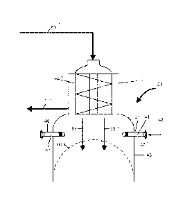
Similar to FIG 2, the conventional hydraulic digester 68 in FIG 3 receives a
slurry of
chips and liquor from a feed system (not shown) via conduit 60'. The feed
system
may be unpressurized or slightly pressurized, and the temperature of the
slurry is
about 110 C or below. The slurry is introduced to the digester 68 by a
conventional
"top separator" 61', which is a downwardly directed screw-conveyor. The liquor
intro-
duced by separator 61 is shown as an arrow 62'; the chips by an arrow 63'. As
the
slurry is transported downwardly by conveyor 61', excess liquor is removed
from the
slurry through a cylindrical screen 64' and returned to the feed system (e.g.
high
pressure feeder or pumps) by conduit 65. The chips introduced by the separator
61'
produce a level of chips 66'. Since the digester 68 is hydraulically full, the
zone 67',
i.e. the liquid phase, above chip level 66' is filled with liquid, so that no
gaseous zone
typically exists.
The digester wall 43 having a continuously curved cross-section is provided
with
steam injectors 40, which comprise tubes 41 extending to the interior of the
digester
68 through the wall. The tubes are connected to a steam source (not shown) for
leading steam (arrow 42) to the digester. The length of the tube 41 inside the
di-
gester may be 150 -2500 millimeters (mm), typically 200-600 mm. The tubes are
lo-
cated above the level of chips 66' and below the lower edge of the top
separator 61'
so that the steam is directed to the liquid phase 67'. The tubes are typically
located
0.1-5.0 meters (m) below the top separator 61' in the vertical direction. When
the
steam is fed, a temperature increase can be from 1 to 40 C, preferably from 5
to 30
C.
CA 02958709 2017-02-20
WO 2016/038251
PCT/F12015/050592
8
The tube 41 has a plurality of openings 50 (FIG. 4a and 4b) for discharging
steam to
the liquor phase 67' above the chip level 66'. Typically the openings are
circular
small holes having a diameter (D) of 0.1-15 millimeters (mm), preferably 1.5-
5.0 mm.
The holes can be configured, typically, as circular holes, but also as gaps or
slots.
The term "hole" should therefore not be given any restrictive meaning, but
should
cover all through openings, slots, etc., regardless of shape.
The openings 50, typically hundreds of small holes, are distributed along the
circum-
ference and the length of the tube wall 52 as a continuous zone 51 or as
separate
zones. The separate zones may be disposed spaced apart along the length and/or
circumference of the tube. The number of the holes 50 depends on the steam
flow
required for heating the chip suspension, and thus the zone or zones can cover
ade-
quate portion(s) of the tube wall. Some portions of the tube wall may be
unperforat-
ed. For instance, the tube end 53 and/or the portion 54 closest to the
digester wall
may be unperforated, whereas the portion 55 therebetween is perforated
partially or
entirely.
FIG. 5 shows that there may be more than one injector 40 (tubes 41) disposed
along
the circumference of the digester wall 43 so that the tubes 41 may be equally
or un-
equally spaced apart from each other. The distance between the tubes may
depend
e.g. on the construction of the top part of the digester.
As shown in FIG. 5, the steam flow from the steam openings 50 is directed
radially
(an arrow 57) and/or circumferentially (an arrow 56) in the digester. The
steam flow
along a circumferential direction may intensify heat transfer in the liquid
phase. The
direction of the steam flow may be defined by the location of the perforated
and un-
perforated zones in the tube wall.
It appears that adding direct steam via steam injectors solves the dominant
problem
regarding hydraulic digester operation. This problem has been too large a
tempera-
ture difference between impregnation and cooking zones. All hydraulic
digesters
would benefit from the steam addition, especially those hydraulic digesters in
which
the impregnation zone temperature has been only about 100 C.
Although only some preferred embodiments of the method according to the
invention
have been described in the above, the invention covers all such modifications
and
variations that are included in the scope defined in the claims.