Note: Descriptions are shown in the official language in which they were submitted.
CA 02959078 2017-02-23
1
Spectacles and method for determining the center of the pupil center of both
of the
wearer's eyes
The invention relates to spectacles.
Spectacles are known which have a camera, which is oriented onto an eye of the
relevant
spectacles wearer. By recording an eye video, the coordinates of the pupil and
the
viewing direction of the eye can be ascertained using such spectacles.
Together with a so-
called field of vision video, which is prepared by a further field of vision
camera arranged
on the spectacles in the viewing direction of a user, the point at which the
user looks can
be ascertained using such spectacles.
Such known spectacles have the disadvantage that the arrangement of the camera
can
itself result in impairment of the behavior of the user. Such spectacles are
generally
conceived as a measurement device or research utensil and are also clearly
recognizable
as such. Test persons do accept the relevant spectacles in regions separated
from public
view, such as a vehicle or a special test environment, but, above all in
environments in
which the relevant test person has to act unshielded from other surrounding
people, they
result in an influence of the behavior of the test person and the persons in
the
surroundings. The feedback which a human receives from the reactions of his
surroundings to his own appearance often has a direct influence on the
behavior of the
relevant person. This influence leads via the unconscious and therefore
withdraws direct
control by the relevant person. Publicly wearing a clearly recognizable and
striking
apparatus on the head results in reactions of the surroundings, which in turn
can have
direct influence on the behavior, also the viewing behavior, of the relevant
test person. In
difficult test situations in this regard, this can result in a high level of
influence of the test
result by way of the means of the test itself.
Such known spectacles record the eye of the test person from the bottom front.
It has
been shown that this camera position can have negative effects on the accuracy
and
quality of the achieved measurement results.
CA 02959078 2017-02-23
2
These known spectacles additionally have the disadvantage that the protruding
parts, such
as cameras and cables, restrict the possible uses of such known spectacles to
the research
uses. For example, such spectacles represent a substantial risk of accident in
the
surroundings of rapidly rotating machines. Pieces of clothing or equipment
objects worn
on the body having loops or protruding parts are forbidden in numerous work
environments for reasons of safety.
US 4 300 818 A describes spectacles having variable refraction properties. The
spectacles
have "lenses" in this case, which can be adjusted in the curvature thereof
Illuminants and
photodiodes are arranged as detectors on the inner side of the frame in the
region of the
center bridge, to coarsely acquire the focal distance of the eyes and adjust
the refraction
properties of the lenses in this manner.
EP 2 499 960 Al describes spectacles for view acquisition, wherein the
spectacles have a
field of vision camera arranged in the central bridge, and a left and a right
camera in each
case, which are each arranged in the lower region of the frame, adjoining the
lens
receptacle openings.
WO 2013/067230 Al describes spectacles which lighten or darken the spectacles
based
on the viewing direction of the wearer and the brightness conditions in the
viewing
direction or the surroundings at which the test subject looks. The relevant
spectacles have
cameras according to one embodiment in this case, which are arranged inside
the frame,
and which are oriented laterally into the spectacle lenses.
The object of the present invention is therefore to specify spectacles of the
type
mentioned at the outset, using which the mentioned disadvantages can be
avoided, and
which have a high level of measurement accuracy in the detection of the pupils
of a test
subject, using which the influence of the spectacles themselves on the viewing
behavior
of the test subject can be reduced, and which are usable in hazardous
surroundings.
In one embodiment, the present invention provides spectacles having a frame,
wherein
the frame has at least one lens receptacle opening for a lens, and wherein the
frame has a
CA 02959078 2017-02-23
3
right nose frame part and a left nose frame part, wherein a right eye
acquisition camera is
arranged in the right nose frame part for preparing a right eye video
consisting of successive
right individual images, and a left eye acquisition camera is arranged in the
left nose frame
part for preparing a left eye video consisting of successive left individual
images.
A detection of the viewing direction of both eyes of a test subject can thus
be performed,
wherein the test subject remain substantially uninfluenced by the measurement
structure.
Better detection of the viewing direction of a test subject can thus be
performed than in the
case of recording only one eye. Due to the so-called binocular measurement, on
the one
hand, the measurement in the middle region, therefore, in a region of the eye
position in
which both eyes are visible by way of the eye acquisition camera assigned to
the respective
eye, can be performed with previously unachieved accuracy, and at the same
time in the
case of so-called lateral position of the eye, therefore, in situations in
which the test subject
more or less looks "out of the comer of his eye", a measurement can be
performed at all for
the first time. Due to the detection of both eyes from the region of the nose
rest or nose
frame part, at any time at least one of the eyes can be recorded from an angle
advantageous
for the measurement accuracy, whereby good measurement results can be
achieved.
By arranging the eye acquisition camera in the nose frame part, influence of
the pupil
detection by eyelashes surrounding the eye can be reduced. Furthermore, the
influence of
interfering reflections on the pupils can thus be reduced. The blinking of the
test subject can
also be recognized more exactly than previously by detecting both eyes of a
test subject.
The focal distance can also be determined by the detection of both pupils of a
test subject,
therefore, the distance at which the relevant test subject focuses. In this
case, by
comparing the measurement to the measured values ascertained for the
individual eyes,
eye misalignments can also be recognized rapidly and easily. For this purpose,
it can be
necessary to calibrate the relevant spectacles in each case individually to
the eyes of the
test subject. Furthermore, measurements can be carried out on individual eyes
using the
present spectacles, for example, in that the other eye is covered in each
case.
CA 02959078 2017-02-23
4
By illuminating the eyes using an infrared radiation source in a darkened
environment, an
analysis of the retina or other parts of the eye can additionally be performed
using the
present spectacles.
By arranging the eye acquisition camera in the nose frame part, spectacles can
be
provided which have a high level of measurement accuracy with respect to the
viewing
direction of the eyes of a user, and which can be worn inconspicuously, so
that no
influence of the behavior of the user is provided because of wearing the
spectacles. Thus,
above all in the case of public use of the spectacles, significantly improved
results can be
achieved, since both the measurement accuracy is increased, and the
measurement
apparatus can now no longer be perceived by the surroundings and therefore
also does not
result in negative influences of the test person. Due to the integration of
the eye
acquisition camera into the nose frame part, the spectacles do not have any
protruding
parts, and are therefore suitable to be worn as work spectacles or protective
spectacles.
The viewing movements of a worker or a person operating a machine can thus not
only
be monitored and analyzed, but rather also can be used directly for
controlling the
machine. In addition, the capability for controlling a machine can thus be
monitored,
because the physical and mental state of the relevant human can be concluded
on the
basis of the eye movements, for example, whether he is overtired or is under
the influence
of psychotropic substances.
The invention furthermore relates to a method for determining pupil center
points of both
eyes of a human.
Another object of the invention is therefore to specify a method of the above-
mentioned
type, using which the disadvantages mentioned at the outset can be avoided,
and with
which, with a high level of measurement accuracy, the focal distance and the
blinking of
a human can be detected, and using which the spectacles can be easily
calibrated.
In another embodiment, the present invention provides a method for determining
pupil
center points of both eyes of a human, wherein the human wears spectacles as
defined
herein, wherein the right pupil of the human is acquired by the right eye
acquisition
CA 02959078 2017-02-23
4a
camera, wherein the right eye acquisition camera prepares a right eye video
consisting of
successive right individual images, wherein right pupil coordinates of a focal
point ¨
corresponding to the right pupil center point ¨ are ascertained from the right
individual
images, wherein the left pupil of the human is acquired by the left eye
acquisition camera,
wherein the left eye acquisition camera prepares a left eye video consisting
of successive
left eye images, wherein pupil coordinates of a focal point ¨ corresponding to
the left pupil
center point ¨ of the left pupil are ascertained from the left eye images, and
wherein the
right pupil center point and/or the left pupil center point is/are stored
and/or output, wherein
a reflective surface is arranged opposite to the human wearing the spectacles,
to calibrate
the spectacles, an illuminant arranged on a front side of the spectacles is
activated, the
human observes the image of the illuminant on the reflective surface and,
while fixing on
the image of the illuminant, moves his head into pre-definable positions at
the same time.
A detection of the viewing direction of both eyes of a human can thus be
acquired. The
viewing direction of a human can thus be determined with high accuracy. Simple
and
automatable calibration of the spectacles is possible by way of the
illuminant.
The invention furthermore relates to a method for recognizing a spontaneous
blink of a
human.
Another object of the invention is therefore to specify a method of the above-
mentioned
type, using which the disadvantages mentioned at the outset can be avoided,
and which
can differentiate with a high level of accuracy between different states, in
particular
concentration and fatigue, of a human.
In another embodiment, the present invention provides a method for determining
a
spontaneous blink of a human, wherein the human wears spectacles as defined
herein,
wherein the right pupil of the human is acquired by the right eye acquisition
camera,
wherein the right eye acquisition camera prepares a right eye video consisting
of successive
right individual images, wherein right pupil coordinates of a focal point ¨
corresponding to
the right pupil center point ¨ are ascertained from the right individual
images, wherein the
left pupil of the human is acquired by the left eye acquisition camera,
wherein the left eye
acquisition camera prepares a left eye video consisting of successive left eye
images,
CA 02959078 2017-02-23
4b
wherein pupil coordinates of a focal point ¨ corresponding to the left pupil
center point ¨ of
the left pupil are ascertained from the left eye images, and wherein the right
pupil center
point and/or the left pupil center point is/are stored and/or output, wherein
the right eyelids
are detected in the successive right eye images, wherein the left eyelids are
detected in the
successive left eye images, and wherein if a right eyelid conceals the right
pupil center
point in right eye image a and a left eyelid conceals the left pupil center
point in a left eye
image, a report of a spontaneous blink is generated and output and/or stored.
A blink can thus be recognized as a spontaneous blink, whereby it is possible
to
differentiate reliably between different states of the relevant human, for
example,
between a state of high concentration and a state of fatigue.
The invention furthermore relates to a method for ascertaining a focal
distance of a
human.
The object of the invention is therefore to specify a method of the above-
mentioned type,
using which the disadvantages mentioned at the outset can be avoided, and
using which
the accuracy when determining the point at which a human looks can be
increased, and
using which the focal distance of the eyes of a human can be detected with a
high level of
measurement accuracy in particular.
In another embodiment, the present invention provides a method for
ascertaining a focus
distance of a human, wherein the human wears spectacles as defined herein,
wherein the
right pupil of the human is acquired by the right eye acquisition camera,
wherein the right
eye acquisition camera prepares a right eye video consisting of successive
right individual
images, wherein right pupil coordinates of a focal point ¨ corresponding to
the right pupil
center point ¨ are ascertained from the right individual images, wherein the
left pupil of the
human is acquired by the left eye acquisition camera, wherein the left eye
acquisition camera
prepares a left eye video consisting of successive left eye images, wherein
pupil coordinates
of a focal point ¨ corresponding to the left pupil center point ¨ of the left
pupil are ascertained
from the left eye images, and wherein the right pupil center point and/or the
left pupil center
point is/are stored and/or output, wherein an intraocular distance is
ascertained from the pupil
CA 02959078 2017-02-23
4c
coordinates, wherein a right viewing angle is assigned to the right pupil
coordinates, wherein
a left viewing angle is assigned to the left pupil coordinates, and wherein
the focus distance is
ascertained from the interocular distance, the right viewing angle, and the
left viewing angle,
and preferably stored and/or output, in particular as a switching pulse.
The focus distance or the focal distance of the eyes of the relevant human can
thus be
ascertained. It can thus be established even more accurately at which point a
human is
actually looking.
The right eye acquisition camera can be oriented on a right region, which
right region is
arranged between 20 mm and 40 mm, in particular between 25 mm and 35 mm, to
the
right of a spectacles center and spaced apart between 10 mm and 20 mm from the
right
eye acquisition camera, and the left eye acquisition camera is oriented on a
left region,
which left region is arranged between 20 mm and 40 mm, in particular between
25 mm
and 35 mm, to the left of the spectacles center and spaced apart between 10 mm
and 20
mm from the left eye acquisition camera. The right eye acquisition camera
and/or the left
eye acquisition camera can be arranged so they are pivotable about at least
one axis, in
particular about two axes, in the right nose frame part or the left nose frame
part,
respectively. The spectacles can have at least one nose bridge receptacle, for
accommodating at least one nose bridge, designed in particular as a saddle
bridge.
At least one field of vision camera can be arranged on the frame. The at least
one field of
vision camera can be arranged in a region between the right nose frame part
and the left
nose frame part.
The spectacles can have a data processing unit and a data interface, the data
processing
unit is connected to the right eye acquisition camera and the left eye
acquisition camera,
the spectacles furthermore have an energy accumulator for the energy supply of
the right
eye acquisition camera and the left eye acquisition camera and also the data
processing
unit and the data interface, wherein preferably the data processing unit and
the data
interface are arranged in a first earpiece, which is connected to the frame,
and wherein
preferably the energy accumulator is arranged in a second earpiece, which is
connected to
4d
the frame. At least one illuminant, in particular an LED, can be arranged on a
front side
of the spectacles, and the illuminant is connected to the data processing
unit, and the
energy accumulator. A lens having pre-definable changeable geometry can be
arranged in
the at least one lens receptacle opening, and the lens is connected to the
data processing
unit. The frame has a U-shaped nose receptacle recess for arranging the
spectacles on the
nose of a human, wherein the right nose frame part and the left nose frame
part laterally
border the nose receptacle recess.
Also provided is a system consisting of spectacles disclosed herein and a pre-
definable
number of different shaped nose bridges, for pre-definable adaptation of the
spectacles to
different persons by replacement of the nose bridges.
In the preferred method for determining pupil center points, using an image
recognition
program, the pupil coordinates for each individual image of the eye video are
automatically ascertained by:
registering the contrasts of the pupil to the surroundings;
seeking out all points of the individual image which are darker than a set
degree
of darkness;
completely acquiring and delimiting a dark area corresponding to the pupil
using
these points; and
ascertaining the focal point of the dark area, which corresponds to the pupil
center
point having the pupil coordinates.
A visual downtime between the beginning of a spontaneous blink and the end of
the same
spontaneous blink can be measured, and if the visual downtime exceeds a
limiting time, a
warning message can be generated and/or output. Using an image recognition
program,
the pupil coordinates for each individual image of the eye video are
automatically
ascertained by:
registering the contrasts of the pupil to the surroundings;
seeking out all points of the individual image which are darker than a set
degree
of darkness;
completely acquiring and delimiting a dark area corresponding to the pupil
using
these points; and
CA 2959078 2017-07-10
4e
ascertaining the focal point of the dark area, which corresponds to the pupil
center
point having the pupil coordinates.
At least one value, which is associated with the ascertained focus distance,
can be taken
from a data memory of a data processing unit for the geometrical determination
of a lens,
which can be arranged in the lens receptacle opening, having pre-definable
variable
geometry, and the geometry of the lens can be set on the basis of the value.
Using an
image recognition program, the pupil coordinates for each individual image of
the eye
video are automatically ascertained by:
registering the contrasts of the pupil to the surroundings;
seeking out all points of the individual image which are darker than a set
degree
of darkness;
completely acquiring and delimiting a dark area corresponding to the pupil
using
these points; and
ascertaining the focal point of the dark area, which corresponds to the pupil
center
point having the pupil coordinates.
The invention will be described in greater detail with reference to the
appended drawings,
in which an embodiment, which is solely a preferred embodiment, is shown as an
example. In the figures:
Figure 1 shows a preferred embodiment of present spectacles in outline;
Figure 2 shows the spectacles according to Figure 1 in horizontal projection;
Figure 3 shows the spectacles according to Figure 1 in a side view;
Figure 4 shows the spectacles according to Figure 1 in a first axonometric
illustration;
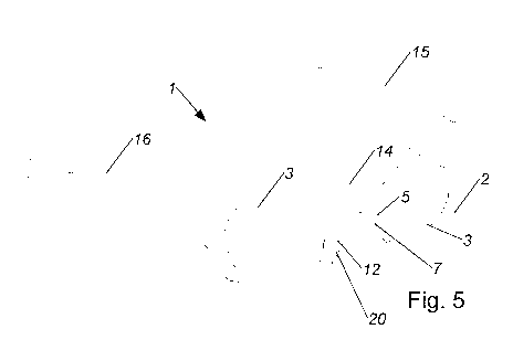
Figure 5 shows the spectacles according to Figure 1 in a second axonometric
illustration;
CA 2959078 2017-07-10
CA 02959078 2017-02-23
Figure 6 shows the spectacles according to Figure 1 in a third axonometric
illustration;
Figure 7 shows a block diagram of a preferred embodiment of present
spectacles;
Figure 8 shows a detail of spectacles according to Figure 1 in horizontal
projection;
Figure 9 shows a detail of spectacles according to Figure 1 in a side view;
and
Figure 10 shows a detail of spectacles according to Figure 1 in a fourth
axonometric
illustration.
Figures 1 to 10 show spectacles 1 having a frame 2, wherein the frame 2 has at
least one lens
receptacle opening 3 for a lens, and wherein the frame 2 has a right nose
frame part 5 and a
left nose frame part 6, wherein a right eye acquisition camera 7 is arranged
in the right nose
frame part 5, and a left eye acquisition camera 8 is arranged in the left nose
frame part 6.
A detection of the viewing direction of both eyes 24 of a test subject can
thus be performed,
wherein he remains substantially uninfluenced by the measurement structure. A
better
detection of the viewing direction of a test subject can thus be performed
than in the case of
recording only one eye 24. Due to the so-called binocular measurement, on the
one hand, the
measurement in the middle region, therefore in a region of the eye position in
which both eyes
24 are visible by way of the eye acquisition camera 7, 8 assigned to the
respective eye 24, can
be performed with previously underachieved accuracy, and at the same time,
with so-called
lateral position of the eyes 24, therefore in situations in which the test
subject more or less
looks "out of the corner of his eye", a measurement can be performed at all
for the first time.
By way of the detection of both eyes 24 from the region of the nose rest or
nose frame parts 5,
6, at any time, at least one of the eyes 24 can be recorded from an angle
advantageous for the
measurement accuracy, whereby good measurement results can be achieved.
CA 02959078 2017-02-23
6
Due to the arrangement of the eye acquisition cameras 7, 8 in the nose frame
parts 5, 6,
influence of the pupil detection by eyelashes surrounding the eye 24 can be
reduced.
Furthermore, the influence of interfering reflections on the pupils can thus
be reduced. The
blinking of the test subject can also be recognized more exactly than
previously by the
detection of both eyes 24 of a test subject.
The focus distance, therefore the distance at which the relevant test subject
focuses, can also
be determined by the detection of both pupils of a test subject. In this case,
eye misalignments
can also be recognized rapidly and easily by comparing the measurement to the
measured
values ascertained for the individual eyes 24. For this purpose, it can be
necessary to calibrate
the relevant spectacles individually in each case to the eyes 24 of the test
subject.
Furthermore, measurements on individual eyes 24 can be carried out using the
present
spectacles 1, for example, in that the other eye 24 is covered in each case.
By illuminating the eyes 24 using an infrared radiation source in a darkened
environment, an
analysis of the retina can additionally be performed using the present
spectacles.
By arranging the eye acquisition cameras 7, 8 in the nose frame parts 5, 6,
spectacles 1 can be
provided, which have a high measurement accuracy with regard to the viewing
direction of
the eyes 24 of a user, and which can be worn inconspicuously, so that no
influence of the
behavior of the user is provided because of wearing the spectacles 1. Thus,
above all in the
case of public use of the spectacles 1, significantly improved results can be
achieved, because
the measurement accuracy is increased, and also the measurement apparatus can
now no
longer be perceived by the surroundings and therefore also does not result in
negative
influences of the test person. Due to the integration of the eye acquisition
cameras 7, 8 in the
nose frame parts 5, 6, the spectacles 1 do not have any protruding parts, and
are therefore
suitable to be worn as work spectacles or protective spectacles. The viewing
movements of a
worker or of a human operating a machine can thus not only be monitored and
analyzed, but
rather can be used directly for controlling the machine. In addition, the
capability for
controlling a machine can thus be monitored, since the physical and mental
state of the
CA 02959078 2017-02-23
7
relevant human can be concluded on the basis of the eye movements, for
example, whether he
is overtired or under the influence of psychotropic substances.
The specifications "right" or "left" relate to the intended manner of wearing
the spectacles 1
by a human.
The present invention relates to spectacles 1 to be worn on the head of a
human. The
spectacles 1 have a frame 2, which can also be referred to as the middle part.
Furthermore, the
spectacles 1 have a first earpiece 15 and a second earpiece 16, which are
connected to the
frame 2. The two earpieces 15, 16 are preferably integrally molded on the
middle part, for
example, while forming a flexible region, which enables bending of the
earpieces 15, 16. It
can also be provided that the two earpieces 15, 16 are connected to the middle
part by means
of a hinge. The earpieces 15, 16 are provided for the purpose, as known per
se, of holding the
spectacles 1 on the head of the wearer, for example, in that they are formed
to engage behind
the ears of the human wearing the spectacles 1.
The frame 2 and the two earpieces 15, 16 are preferably formed comprising a
plastic.
The frame 2 has at least one lens receptacle opening 3, in which a lens is
preferably arranged,
this lens also being referred to colloquially and independently of the
material thereof as a
glass or spectacle lens. According to the illustrated preferred embodiment, it
is provided that
the spectacle 1 has two lens openings 3, and one lens is arranged in each of
the two lens
receptacle openings 3. The lenses can also be optical and/or tinted lenses.
Such viewing
analyses are also possible in the case of wearers of optical spectacles by the
present spectacles
1.
The frame 2 has, in a way known per se, a U-shaped nose receptacle recess,
which is provided
for arranging the spectacles 1 on the nose of a human. The regions of the
frame 2 which
laterally border this recess are referred to as the right nose frame part 5
and the left nose frame
part 6. The right and the left nose frame parts 5, 6 are preferably regions of
the frame 2
CA 02959078 2017-02-23
8
enclosing the lens receptacle openings 3 which merge directly and/or
integrally into the
further regions of the frame 2. The nose frame parts 5, 6 can also be referred
to as nose part
frames 5, 6.
It can also be provided that the frame 2 does not enclose the at least one
lens receptacle
opening 3 on all sides, and the lens receptacle opening 3 is therefore
designed as a rimless
recess.
The surface which is provided for direct contact with the nose of the
spectacles-wearing
human is referred to as the nose rest surface 20. It can be provided that
these nose rest
surfaces 20 are formed as integral parts of the frame 2. It is preferably
provided that the
spectacles 1 have at least one nose bridge receptacle 11, for accommodating at
least one nose
bridge 12.
The nose bridge receptacle 11 is arranged in this case in or on the U-shaped
nose receptacle
recess of the frame 2. In this case, the nose bridge receptacle 11 has a part
of a catch
connection, and the nose bridges 12 provided to be arranged in the nose bridge
receptacle 11
have the corresponding other part of such a catch connection.
It is preferably provided that the spectacles, as shown in the figures, only
have a single nose
bridge receptacle 11, in which a one-piece U-shaped nose bridge 12 is
arranged, which is also
referred to as a saddle bridge. However, it can also be provided that a nose
bridge receptacle
11 is arranged in each case on each of the two nose frame parts 5, 6, for
accommodating one
nose bridge 12 each. Different-shaped nose bridges 12 can be used in the
spectacles 1 by way
of the nose bridge receptacle 11, and the spectacles can thus be adapted to
different nose
geometries, whereby the spectacles 1 can be adapted using simple means to
different humans,
wherein it can also be provided in particular that nose bridges 12 are
intentionally adapted to
single individuals. The spectacles 1 can be provided in a set or system
together with different-
shaped nose bridges 12, for pre-definable adaptation of the spectacles 1 to
different persons
CA 02959078 2017-02-23
9
by replacement of the nose bridges 12. The at least one nose bridge 12 is
preferably formed
comprising silicone and/or an elastomer.
It is provided that a right eye acquisition camera 7 is arranged in the right
nose frame part 5,
and a left eye acquisition camera 8 is arranged in the left nose frame part 6.
The two eye
acquisition cameras 7, 8 are arranged in this case in the parts of the frame 2
which are
arranged closest to the nose receptacle recess. The two eye acquisition
cameras 7, 8 are
designed as digital cameras and have an objective lens. The two eye
acquisition cameras 7, 8
are each provided to film one eye of the human wearing the relevant spectacles
1, and to
prepare in each case an eye video consisting of individual eye images or
individual images.
A primary purpose of the eye acquisition cameras 7, 8 is to acquire the pupil
of the human
wearing the spectacles 1. It is therefore sufficient if the entire eye cannot
be acquired by the
respective eye acquisition camera 7, 8, but rather only a region around the
pupil of the
respective eye. The eye acquisition cameras 7, 8 can also be referred to as
pupil acquisition
cameras. The eye acquisition cameras 7, 8 have a suitable focal length to
acquire the
corresponding regions of the eye from the position in the nose frame part. The
focal length
and the aperture angle which can be acquired using a focal length are
dependent on the sensor
size of the camera and can be selected without problems by the embodying
person skilled in
the art using the present specifications.
The right eye acquisition camera 7 is oriented onto a right region 9, in
which, when the
spectacles 1 are arranged on the head of a human, the right eye 24 of this
human is at least
regionally arranged in a variety of humans. Correspondingly, the left eye
acquisition camera 8
is oriented onto a left region, in which, in a variety of humans, the left eye
of the human is at
least regionally arranged. The position of the right region 9 and the left
region, and therefore
the viewing direction of the two eye acquisition cameras 7, 8, are
individually different.
However, there are statistic probabilities depending on sex and ethnic
affiliation with respect
to the position of the eyes and also the nose geometry, which enable the
viewing direction of
the two eye acquisition cameras 7, 8 to be specified, at least for individual
regions or
CA 02959078 2017-02-23
countries, such that the relevant spectacles are matching for a large number
of humans in the
relevant region.
According to one preferred embodiment of the present spectacles, it is
provided that the right
region 9 is arranged between 20 mm and 40 mm, in particular between 25 mm and
35 mm, to
the right of a spectacles center 10, the corresponding distance 25 is shown in
Figure 8, and is
arranged spaced apart between 10 mm and 25 mm from the right eye acquisition
camera 7,
and the left region is arranged between 20 mm and 40 mm, in particular between
25 mm and
35 mm, to the left of the spectacles center 10, and spaced apart between 10 mm
and 25 mm
from the left eye acquisition camera 8. Because spectacles 1 are generally
constructed
symmetrically, they also have an unambiguously defined center. The distance
from the eye
acquisition cameras 7, 8 is to be measured in the direction of the extension
of the earpieces
15, 16 or the head receptacle region of the spectacles 1. A good basic
adaptation to the head
shape in Europe and North America can be achieved by the specified values.
Spectacles for
the Asiatic, African, Latin American, or Pacific region are accordingly to be
designed using
other values, in consideration of the specifications of the subject matter.
Figures 8, 9, and 10 each show detail views of the present spectacles 1. A
coordinate system
is shown in the relevant figures 8, 9, and 10. Proceeding from the symmetry of
the relevant
spectacles 1, this coordinate system was selected such that the YZ plane
spanned by the Y
axis and the Z axis on the right and left sides of the spectacles each
intersect opposing or
symmetrically-arranged regions. The XZ plane spanned by the X axis and the Z
axis is
arranged on the YZ plane perpendicularly and in parallel to the plane of
symmetry of the
spectacles. The XY plane is arranged perpendicularly to the YZ plane and the
XZ plane. The
right eye acquisition camera 7 and the left eye acquisition camera 8 are each
arranged inclined
in relation to these planes or axes. In this case, according to one preferred
embodiment, it is
provided that in each case one optical axis 23 of the two eye acquisition
cameras 7, 8 is
arranged at a first angle 21 in relation to the Y axis, and the first angle 21
is between 30 and
50 . Furthermore, it is provided according to the preferred embodiment that in
each case one
CA 02959078 2017-02-23
11
optical axis 23 of the two eye acquisition cameras 7, 8 is arranged at a
second angle 22 in
relation to the X axis, and the second angle 22 is between 25 and 35 .
Different nose bridges 12 can be used for adapting the spectacles 1, as
already described.
Alternatively and/or additionally thereto, it can be provided that the right
eye acquisition
camera 7 and/or the left eye acquisition camera 8 are arranged so they are
pivotable about at
least one axis, in particular about two axes, in the right nose frame part 5
or the left nose
frame part 6. The viewing direction of the right and/or left eye acquisition
camera 7, 8 can
thus be adjusted. An adaptation of the spectacles 1 to different head shapes
is thus possible.
According to one preferred embodiment of present spectacles 1, it is provided
that at least one
field of vision camera 13 is arranged on the frame 2. The field of vision
camera 13 is provided
to record a field of vision video consisting of individual and successive
field of vision images.
The recordings of the two eye acquisition cameras 7, 8 and the at least one
field of vision
camera 13 can thus be entered in correlation in the field of vision video of
the respective
viewpoint. The field of vision camera 13 is only explicitly shown in Figure 1
on the
spectacles 1.
It is preferably provided that the at least one field of vision camera 13 is
arranged in a region
or a bridge between the right nose frame part 5 and the left nose frame part
6. A larger
number of field of vision cameras 13 can also be arranged in the spectacles 1,
wherein in
particular one left and one right field of vision camera is provided in the
frame 2 in each case
in the region of the transition to the first or second earpiece 15, 16,
respectively.
It is preferably provided that the spectacles 1 have a data processing unit 17
and a data
interface 18, the data processing unit 17 is connected to the right eye
acquisition camera 7 and
the left eye acquisition camera 8, the spectacles 1 furthermore have an energy
accumulator 19
for the energy supply of the right eye acquisition camera 7 and the left eye
acquisition camera
8, and also the data processing unit 17 and the data interface 18.
CA 02959078 2017-02-23
12
According to one particularly preferred embodiment of present spectacles 1 it
is provided that
the data processing unit 17 and the data interface 18 are arranged in the
first earpiece 15, and
the energy accumulator 19 is arranged in the second earpiece 16. In this case,
the first
earpiece 15 can either be the right or the left earpiece, and vice versa. The
entire recording,
initial analysis, and storage of the recorded videos can thus be performed in
or by the
spectacles 1 themselves. Interfering connections can thus be omitted.
Figure 7 shows a block diagram of correspondingly designed spectacles 1,
wherein the
external contours of the block diagram are to symbolize the spectacles 1. The
three cameras,
the field of vision camera 13, the right eye acquisition camera 7, and the
left eye acquisition
camera 8, are arranged in the middle part or frame 2. They are preferably at
least indirectly
connected by circuitry to the energy accumulator 19, which is preferably
designed as a
battery, arranged in the second earpiece 16. A data processing unit 17, which
also comprises a
data memory, is arranged in the first earpiece 15. It is preferably designed
as a combination of
a microcontroller or DSP together with a RAM. The data processing unit 17 is
connected in a
signal-conducting manner to a data interface 18. It can also be provided that
the data interface
18 and the data processing unit 17 are formed jointly in hardware, for
example, by an ASIC or
an FPGA. The interface is preferably designed as a wireless interface, for
example, according
to the Bluetooth standard or IEEE 802.x, or as a wired interface, for example,
according to the
USB standard, wherein in this case the spectacles 1 have a corresponding
socket, for example,
according to micro-USB. The data processing unit 17 and the data interface 18
are connected
at least indirectly to the energy accumulator 19 by circuitry, and are
connected in a signal-
conducting manner to the three cameras, the field of vision camera 13, the
right eye
acquisition camera 7, and the left eye acquisition camera 8.
As already described, the present described spectacles 1 are particularly well
suitable for
carrying out a method for determining pupil center points of both eyes of a
human. In this
case, it is provided that the right pupil of the human is acquired by the
right eye acquisition
camera 7, wherein the right eye acquisition camera 7 prepares a right eye
video consisting of
CA 02959078 2017-02-23
13
successive right individual images, wherein the right pupil coordinates within
the right eye
images of a focal point ¨ corresponding to the right pupil center point ¨ of
the right pupil are
ascertained from the right eye images, wherein the left pupil of the human is
acquired by the
left eye acquisition camera 8, wherein the left eye acquisition camera 8
prepares a left eye
video consisting of successive left individual images, wherein pupil
coordinates within the
left eye images of a focal point ¨ corresponding to the left pupil center
point ¨ of the left pupil
are ascertained from the left eye images, and wherein the right pupil center
point and/or the
left pupil center point is/are stored and/or output.
A detection of the viewing direction of both eyes 24 can thus be acquired. The
viewing
direction of a human can thus be determined with a high level of accuracy.
Additionally or
alternatively, the focus distance or the focal distance of the eyes of the
relevant human can
thus be ascertained. A blink can thus be recognized as a spontaneous blink,
whereby it is
possible to differentiate reliably between different states of the relevant
human, for example,
between a state of high concentration and a state of fatigue.
It is preferably provided that a computer objective lens distortion correction
is carried out in
each case for the two eye acquisition cameras 7, 8 and the field of vision
camera 13, as well
as a correction of prospective distortions.
The two eye videos and the field of vision video are recorded in chronological
synchronization, which is controlled by the data processing unit 17.
The ascertainment of the pupil coordinates and the correlation with a field of
vision video, as
is also preferably provided in the present spectacles 1 or present method, is
described in EP 1
300 018 B 1.
In the preferred method, the precise pupil coordinates of the pupil center
point in the eye
video are ascertained by an image recognition program. In this case, the pupil
coordinates are
ascertained for each individual image of the eye video. The ascertainment of
the pupil
CA 02959078 2017-02-23
14
coordinates is preferably performed automatically using an image recognition
program. For
this purpose, for each individual image of the eye video, the contrasts of the
pupils to the
surroundings are registered and all points of the individual image which are
darker than a set
degree of darkness are searched for. Using these points, a dark area is
completely acquired
and delimited, and the focal point of this dark area is then automatically
ascertained. Because
the dark area corresponds to the pupil of the test person, the focal point of
the dark area
represents the pupil center point. The image recognition program preferably
offers setting
variants for the corresponding contrast and the degree of darkness, so that a
particularly high
level of accuracy can be achieved for all individual images. As already noted
above, points
can additionally be selected on the edge of the pupil, which can be identified
particularly well
and reliably because of the contrast to the surroundings, and these points can
be taken as part
of an ellipse, whereupon the focal point or center point of an ellipse is
calculated, on the
circumference of which the pre-definable number of points also lie. For each
individual
image, the best contrast in each case in the form of a grayscale value
threshold can therefore
be ensured for different lighting conditions, which makes reliable
determination of the pupil
coordinates possible overall. The grayscale value threshold is the value which
is, for example,
in digitized form between 1 and 256 and defines the percentage proportion of
black or white
on a pixel. The highest achievable value corresponds to solid black, and the
lowest value to
white. Because the pupil presumably never reaches the solid black value during
the recording,
a value is to be defined which ¨ at least for this image ¨ corresponds to the
real existing pupil
gray. The threshold value excludes all pixels which are brighter than the
defined gray value,
all darker regions are used for finding the focal point. Three parameters
enable the threshold
definition to be optimized. Because the lighting conditions often change very
strongly during
the experiments within the sequence, this threshold value definition is
preferably also possible
individually for each image. All settings can be stored in accordance with the
high
requirements for each image of the sequence in a file.
Proceeding from the ascertained pupil coordinates, the file can be processed
further
differently, for example, by the correlation described in EP 1 300 018 B1 with
a field of
vision video, which is prepared by the field of vision camera.
CA 02959078 2017-02-23
It is preferably provided that the spectacles 1 are calibrated on the basis of
a pre-definable
viewing sequence before ascertaining the pupil center points. For this
purpose, firstly one or
more pattern viewing sequences of the test person on one or more specific
predefined control
points are recorded. A pattern viewing sequence is to be understood as a
viewing sequence
which is recorded solely for the calibration, and during which the test person
looks at
predefined control points. For example, a specific control point can be marked
on a wall. To
obtain the best possible contrast, for example, a black marking on an
otherwise white surface
can be selected as a control point. The control point is generally a cross or
a spot of light or
the like. The test person is instructed to fix on this control point, wherein
the field of vision
and the eye of the test person are recorded by the two eye acquisition cameras
and the field of
vision camera. The control points to be targeted are additionally preferably
arranged at
different defined intervals.
According to a preferred refinement of the present spectacles, it is provided
that at least one
illuminant 26, in particular an LED, is arranged on a front side of the
spectacles 1, and the
illuminant 26 is connected to the data processing unit 17 and the energy
accumulator 19. In
this case, the side facing away from the wearer of the spectacles 1 is
identified as the front
side of the spectacles 1. Simple and automatable calibration of the spectacles
1 is possible by
way of the illuminant 26. The illuminant is controlled for this purpose by the
data processing
unit 17.
It is preferably provided in this case that a reflective surface, in
particular a mirror, is arranged
opposite to the human wearing the spectacles, or the relevant human is placed
in front of a
mirror, and the illuminant 26 is activated for the calibration of the
spectacles 1. The relevant
human now observes his image in the mirror and fixes on the image of the
illuminant in this
case. By pre-definable variation of the position of the head with continuous
fixation on the
illuminant image in the mirror, the positions of the pupils change in relation
to the spectacles
1 or the eye acquisition cameras 7, 8. Because the wavelength or color of the
illuminant 26 is
CA 02959078 2017-02-23
16
known, it can be easily recognized by the field of vision camera 13 and the
data processing
unit 17.
As already mentioned, it is possible, using the present spectacles 1 and the
above-described
method in the refinement thereof, to recognize a spontaneous blink as such, in
contrast, for
example, to the lid movements as are triggered by a foreign body entering the
eye. It is
provided in this case that furthermore, the right eyelids are detected in the
successive right
individual images, wherein the left eyelids are detected in the successive
left individual
images, and wherein, when a right eyelid conceals the right pupil center point
in a right
individual image and a left eyelid conceals the left pupil center point in one
of the individual
images, a message of a spontaneous blink is generated and output and/or
stored. The relevant
right and left individual images which are set forth in the mentioned
condition are each
individual images recorded substantially simultaneously with respect to time.
To detect the eyelids, it is provided that firstly the respective pupils are
completely acquired.
By means of an image processing program having pattern recognition, it is
easily possible to
recognize the concealment of the pupil continuously progressing from one image
to the next
as such and to differentiate it from a highlight. A regional concealment of
the respective
pupils can be easily and reliably assigned to a blink in this manner.
In a refinement of the relevant method for the method for recognizing a
spontaneous blink, it
is furthermore provided that a visual downtime between the beginning of a
spontaneous blink
and the end of the same spontaneous blink is measured, and if a limiting time
is exceeded by
the visual downtime, a warning message is generated and/or output. The
physical and/or
mental state of a human can thus be easily monitored. Present spectacles 1 can
thus monitor,
in cooperation with a machine, whether the human operating the machine applies
the
attentiveness considered to be required for this activity. Thus, for example,
the spectacles 1
can analyze on the basis of the blinking activities of the relevant operator
whether he is
overtired, and safe further operation of the machine is endangered. The
spectacles 1 can then,
CA 02959078 2017-02-23
17
for example, emit a warning message to turn off the relevant machine or can
trigger other
switching procedures.
In a refinement of the method for determining the pupil center points of both
eyes of a human,
it is provided that furthermore the focus distance of a human is ascertained,
wherein an
interocular distance is ascertained from the pupil coordinates in the
individual images of the
field of vision video, wherein a right viewing angle is assigned to the right
pupil coordinates,
wherein a left viewing angle is assigned to the left pupil coordinates, and
wherein the focus
distance is ascertained from the interocular distance, the right viewing
angle, and the left
viewing angle, and is preferably stored and/or output. In particular,
switching pulses or
switching commands can be generated and output in this case.
In this case, to ascertain the focus distance, the interocular distance and
the respective viewing
angle of the two eyes are ascertained. The interocular distance forms the base
of an imaginary
triangle, wherein the viewing angles of the two eyes represent the angles
which the two sides
occupy in relation to the base. The height of the relevant triangle can be
easily ascertained
therefrom as the focus distance or focal distance, where it can be established
more accurately
at which point a human is actually looking.
In addition, misalignments of the eyes can be recognized easily and reliably
by individual
measurements on the two eyes of a test subject. It can be necessary in this
case to calibrate the
eye acquisition cameras 7, 8 separately in each case for the two eyes, for
example, in that one
eye is covered.
According to one advantageous refinement of the invention, it can be provided
that the
ascertained focus distance is used to set or control lenses, which are
arranged in the lens
receptacle openings 3, having variable or pre-definably variable geometry. It
is preferably
provided in this case that the at least one lens is connected to the data
processing unit 17. To
set the relevant geometric parameters on the relevant lens, it is necessary
for the respective
focus distances or distance intervals to be determined to be stored in the
memory assigned to
CA 02959078 2017-02-23
18
the data processing unit 17. The relevant parameters can each contain multiple
variables for
each focus distance in this case. To set the geometry of the relevant lenses,
it is preferably
provided that at least one value, which is associated with the ascertained
focus distance, for
the geometric determination of the lens having pre-definable variable geometry
is taken from
the data memory, and the geometry of the lens is set on the basis of the
value. Spectacles 1
can thus be provided, which can provide reliable aid even in the case of
complicated visual
impairments.
In addition, anomalies, predominantly in the pupils and/or iris region, can be
recognized from
the images of the two eyes.
In conjunction with pre-definable experimental sequences to be carried out,
the navigation
structures or patterns of the eyes can be recorded simultaneously. In
addition, they can be
analyzed and compared, so that real ophthalmological initial examinations are
possible.