Note: Descriptions are shown in the official language in which they were submitted.
CA 02959390 2017-02-24
WO 2016/036842 PCT/US2015/048119
TITLE
REEL ROTATION DEVICE FOR USE WITH
FIBER OPTIC CABLE STORAGE REEL
FIELD OF THE INVENTION
Embodiments of the present invention relate generally to the manufacture
and storage of fiber optic cables and other cable-like products such as
conventional
wire. More specifically, embodiments of the present invention relate to a
device for
rotating the orientation of a cable storage reel prior to shipping.
BACKGROUND
Optical fiber is typically supplied and installed as fiber optic cable. Fiber
optic
cable includes the actual optical fiber plus the structure in which it is
carried and
protected during and after installation. In this regard, fiber optic cable
generally
includes the optical fiber, aramid fibers or other strength members, and an
outer
jacket. Multiple optical fibers are often combined in a multi-fiber cable,
which
efficiently carries the requisite number of fibers to the point(s) of applied
use. "Fiber
optic cable," as used herein, refers generally to fiber optic cable containing
any
number of optical fibers and any combination of strengthening or protective
members.
As fiber optic cable leaves the production line, it is typically wound on
large
reels which are placed on respective pallets for shipping and delivery. In
this regard,
the storage reels are similar to reels used to store other types of cables
(including
conventional metal wire). Often, these reels can be very heavy and difficult
to handle
due to the long lengths of cable that they may contain. In some cases, for
example,
the reels may be loaded on a shipping pallet in a vertical orientation while
other
situations require the reel to be positioned on a flat pallet in a horizontal
position.
1
CA 02959390 2017-02-24
WO 2016/036842 PCT/US2015/048119
Moving the reel from the vertical orientation to a horizontal orientation
without
damaging the reel or the cable it contains can be an arduous task. Moving the
reel
from place to place in the manufacturing or storage facility can also be
difficult.
SUMMARY
Example embodiments of the present invention recognize and address
various considerations of prior art constructions and methods.
One aspect of the present invention provides a reel rotation device comprising
an L-shaped frame with a first side for supporting a reel when the frame is in
a
vertical position orientation and a second side for supporting the reel when
the
frame is in a horizontal position orientation. A first support arrangement is
connected to the first side of the frame and adapted to elevate the reel in
the vertical
position orientation. A second support arrangement is connected to the second
side
of the frame and adapted to elevate the reel in the horizontal position
orientation. At
least one transition element is positioned at a vertex of the L-shaped frame.
The reel
rotation device may be moved from its vertical position orientation to its
horizontal
position orientation by transitioning off of the first support arrangement,
onto the at
least one transition element, and onto the second support arrangement such
that the
reel itself will be re-oriented from vertical to horizontal.
According to some exemplary embodiments, the first and second support
arrangements may provide a clearance gap at an outer surface of the least one
transition element when the L-shaped frame is in the vertical position
orientation
and the horizontal position orientation, respectively. The first and second
support
arrangements preferably comprise a respective set of support members, such as
caster wheels.
2
CA 02959390 2017-02-24
WO 2016/036842 PCT/US2015/048119
Preferably, distal ends of the first and second sides of the L-shaped frame
comprise respective lift structures, such as protruding brackets, configured
to
receive a lifting connection.
The at least one transition element preferably defines an arcuate outer
surface. For example, the at least one transition element may comprise first
and
second transition discs. These transition discs may be attached to outer
lateral sides
of the L-shaped frame at the vertex thereof.
In exemplary embodiments, the first and second sides of the frame each
include a plurality of support bars. For example, the support bars of first
side of the
L-shaped frame may be supported for rotation to facilitate moving the reel on
and off
of the reel rotation device.
Another aspect of the present invention provides a method of moving a reel
carrying a length of elongate cable between a vertical position and a
horizontal
position. One step of the method involves providing a reel rotation device
having an
L-shaped frame with a first side for supporting the reel when the frame is in
a
vertical position orientation and a second side for supporting the reel when
the
frame is in a horizontal position orientation. At least one transition element
is
positioned at a vertex of the L-shaped frame. According to another step, the
reel is
located on the first side of the L-shaped frame such that it will be situated
vertically.
The L-shaped frame is moved from its vertical position orientation to its
horizontal
position orientation by transitioning off of the first support arrangement,
onto the at
least one transition element, and onto the second support arrangement such
that the
reel itself will be re-oriented from vertical to horizontal.
According to another aspect, a reel rotation device comprises a frame with a
first side for supporting a reel when the frame is in a vertical position
orientation and
3
CA 02959390 2017-02-24
WO 2016/036842 PCT/US2015/048119
a second side for supporting the reel when the frame is in a horizontal
position
orientation, the first side and the second side being substantially
perpendicular to
each other. At least one transition element is positioned at a vertex location
between
the first side and the second side of the frame, the transition element having
an
arcuate outer surface. The reel rotation device may be moved from its vertical
position orientation to its horizontal position orientation by transitioning
off of the
first support arrangement, onto the at least one transition element, and onto
the
second support arrangement such that the reel itself will be re-oriented from
vertical
to horizontal.
Those skilled in the art will appreciate the scope of the present invention
and
realize additional aspects thereof after reading the following detailed
description of
example embodiments in association with the accompanying drawing figures.
BRIEF DESCRIPTION OF THE DRAWINGS
A full and enabling disclosure of the present invention, including the best
mode thereof directed to one of ordinary skill in the art, is set forth in the
specification, which makes reference to the appended drawings, in which:
Fig. 1 is perspective view of a prior art cable shipping arrangement in which
the reel is positioned upright (i.e., vertically) on a wooden pallet;
Fig. 2 is a perspective view of a prior art cable shipping arrangement in
which
the reel is placed on its side (i.e., horizontally) on a wooden pallet;
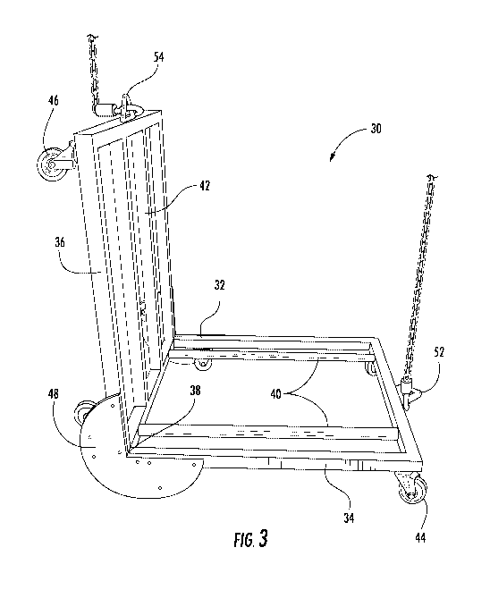
Fig. 3 is a perspective view of an exemplary reel rotation device which may be
constructed in accordance with an embodiment of the present invention;
Fig. 4 is a diagrammatic end view of an exemplary reel rotation device
constructed in accordance with an embodiment of the present invention with one
transition disc removed for clarity;
4
CA 02959390 2017-02-24
WO 2016/036842 PCT/US2015/048119
Fig. 5 is a perspective view of an exemplary reel and reel rotation device
constructed in accordance with an embodiment of the present invention, where
the
reel is positioned vertically; and
Fig. 6 is a perspective view of an exemplary reel and reel rotation device
constructed in accordance with an embodiment of the present invention, where
the
reel is positioned horizontally.
Repeat use of reference characters in the present specification and drawings
is intended to represent same or analogous features or elements of the
invention.
DETAILED DESCRIPTION
Reference will now be made in detail to example embodiments of the present
invention, one or more examples of which are illustrated in the accompanying
drawings. Each example is provided by way of explanation of the invention, not
limitation of the invention. In fact, it will be apparent to those skilled in
the art that
modifications and variations can be made in the present invention without
departing
from the scope or spirit thereof. For instance, features illustrated or
described as
part of one embodiment may be used on another embodiment to yield a still
further
embodiment. Thus, it is intended that the present invention covers such
modifications and variations.
Some embodiments of the present invention are particularly suitable for use
in packing and shipping fiber optic cable, and the below discussion will
describe
example embodiments in that context. However, those of skill in the art will
understand that the present invention is not so limited. In fact, it is
contemplated
that embodiments of the present invention may be used in other situations to
assist
in packing and shipping other types of wire, cable, or reel-packaged products.
In this
5
CA 02959390 2017-02-24
WO 2016/036842 PCT/US2015/048119
regard, a reel of fiber optic cable is used in discussion for the purposes of
explanation
only and is not meant to be limiting.
As discussed above, fiber optic cable often comprises many optical fibers and
strength members in a protective sheath. After the components are fully
encased in
the protective sheath, the cable leaves the production line and is fed to a
winding
machine which winds the desired length of a cable on a reel. During the
winding
process, the reel is rotated while in the upright (or vertical) position.
Referring to Fig. 1, the reel 10 of cable is often situated after winding on a
support pallet 12 in the vertical position. In this case, the reel 10 remains
on pallet 12
in the vertical position for shipping. The top of the vertical support pallet
12 has a
bracing structure 14 which helps stabilize the reel 10 in the vertical
position. In
addition, a securing band 16, fed through the center of the reel 10, is
tightly secured
to the vertical support pallet 12. Finally, the reel 10 and pallet 12 may be
optionally
wrapped in shrink wrap 18. Notably, this method of shipping does not require
the
reel to be re-oriented from its vertical position after winding.
An alternative shipping configuration is shown in Fig. 2. In this
configuration,
the reel 10 is placed on its side, i.e., in a horizontal position, on a
standard flat pallet
22. Securing straps 24 are included to further secure the reel 10 to the
pallet 22. It
will be appreciated that, when the reel 10 is placed in the horizontal
position, the
tendency of the reel 10 to roll is eliminated. However, this shipping
configuration
requires that the reel 10 be re-oriented on its side from the vertical
position. As
noted above, moving the reel from vertical to horizontal orientation is
difficult.
A reel rotation device 30 in accordance with an example embodiment of the
present invention will now be discussed with reference to Figs. 3-6. Such a
reel
rotation device 30 allows a reel 10 to be rotated (i.e., re-oriented) from its
vertical
6
CA 02959390 2017-02-24
WO 2016/036842 PCT/US2015/048119
position to its horizontal position in a relatively quick and easy manner.
After such
rotation, the reel 10 may be easily transferred to a standard pallet 22 for
shipping.
The reel rotation device 30 has an L-shaped frame 32 with a first side 34 and
a
second side 36 that extend perpendicularly from its vertex 38. The L-shaped
frame
32 is preferably made of metal (such as tubular steel), but other suitable
rigid
materials are also contemplated. The first side 34 is configured to support
the reel 10
when it is oriented in its vertical position¨e.g., after winding (see Fig. 5).
In this
embodiment, first side 34 comprises a pair of round cross-section support bars
40
that provide a seat in which the vertically-oriented reel 10 is received.
Preferably,
support bars 40 may be mounted for rotation in the first side 34 of frame 32,
which
further facilitates moving reel 10 onto and off of the reel rotation device
30.
The second side 36 of the L-shaped frame 32 is configured to support the reel
10 when it is oriented in its horizontal position (see Fig. 6). Preferably,
one or more
cross bars 42 extend across the second side 36 frame to provide a flat surface
for
supporting the bottom of the reel 10.
In this embodiment, suitable transition elements are located at the vertex 38
of the L-shaped frame 32. In the example embodiment shown in Figs. 3-6, the
transition elements comprise partial discs 48 spanning about 270 degrees on
the
exterior portion of the vertex 38 of the L-shaped frame 32. Transition discs
48 may
be attached, for example, on the outer lateral side of frame 32, using
suitable
fasteners (e.g., screws) or other suitable means of attachment. The arcuate
perimeter
of transition discs 48 thus provides a pivot for rotating the L-shaped frame
32. The
radius of the transition discs and the location of the disc center point
(origin) with
respect to the vertex 38 can be chosen to facilitate gradual rotation. For
example, the
7
CA 02959390 2017-02-24
WO 2016/036842 PCT/US2015/048119
disc center point (origin) may be offset from the vertex 38 in some
embodiments (as
shown).
Furthermore, each of the first and second sides 34, 36 has a set of support
members, such as support casters 44 and 46, respectively, that elevate each
such
frame side above the floor (or other ground surface). In this case, four first-
side
support casters 44 support the weight of the L-shaped frame 32 and reel 10
when in
its vertical position. Four second-side support casters 46 support the weight
of the L-
shaped frame 32 and reel 10 when in its horizontal position. As best seen in
Fig. 4,
the casters support the frame 32 while providing a clearance gap 50 defined by
the
radius of transition discs 48 so that the reel rotation device 30 can be
easily moved
around the production floor. Furthermore, the height of the second side 36
support
frame in the horizontal position (i.e., distance from the floor) is preferably
substantially the same height as a standard pallet 22. As a result, the reel
10 can be
easily slid from the L-shaped frame 32 to the standard pallet 22 for shipping.
As best seen in Fig. 3, the L-shaped frame 32 has lifting brackets 52, 54 on
the
distal end of both the first and second sides 34, 36 of the L-shaped frame 32,
respectively. Lifting rope or chain may be attached to each of the lifting
brackets 52,
54 and be used to rotate the reel rotation device 30 from its vertical to
horizontal
position, and vice versa. As the chain attached to the first-side lifting
bracket 52 is
raised, the weight of the frame 32 and reel 10 shifts off of the first-side
support
casters 44 and onto the outer surface of the transition discs 48. As the
rotation
continues, the chain connected to the second-side lifting bracket 54 supports
the
weight of the frame 32 as it is transferred from the transition disc 48 onto
the
second-side support casters 46. By adjusting the tension in the two lifting
chains, a
controlled rotation of the L-shaped frame 32 and reel 10 can be achieved.
8
CA 02959390 2017-02-24
WO 2016/036842 PCT/US2015/048119
One skilled in the art will appreciate that many modifications to the
previously discussed example embodiment are possible and any such
modifications
are within the scope of the invention. For example, the support members could
be
support legs instead of casters, and the number of support members could vary
depending on load and balance considerations. In such an embodiment, for
example,
the transition discs could act as permanent support legs such that only
support legs
on the distal ends of the first and second sides are needed. Furthermore, the
lifting
brackets can be modified or the lifting mechanism changed depending on the
load
and lifting requirements.
While one or more example embodiments of the invention have been
described above, it should be understood that any and all equivalent
realizations of
the present invention are included within the scope and spirit thereof. The
embodiments depicted are presented by way of example only and are not intended
as limitations upon the present invention. Thus, it should be understood by
those of
ordinary skill in this art that the present invention is not limited to these
embodiments since modifications can be made. Therefore, it is contemplated
that
any and all such embodiments are included in the present invention as may fall
within the scope and spirit thereof.
9