Note: Descriptions are shown in the official language in which they were submitted.
MOBILE SHELTERED WORKSTATION
BACKGROUND OF THE INVENTION
This invention relates to weather shelters and, more particularly, to a mobile
sheltered workstation that provides shelter to a worker from weather elements.
Persons working outdoors often need a quick and convenient portable
shelter from the weather. Gardeners, painters, utility workers, carpenters,
builders,
contractors, and coaches may need shelter from the blazing sun while they
work.
Police officers working an accident scene may need shelter from rain or snow.
A
mobile sheltered workstation can improve work conditions in virtually any
location. In addition, workers may also need safe and convenient access to
electricity while they work.
Various devices have been proposed in the art for providing a mobile
sheltered workstation. Although assumably effective for their intended
purposes,
the current devices are too bulky, hard and time consuming to setup, and do
not
provide sufficient shelter. Additionally, the current devices do not provide
safe and
convenient access to electricity.
Therefore, it would be desirable to have a mobile sheltered workstation that
includes a canopy framework that is quickly and easily movable between a
stowed
configuration and a deployed configuration. Further, it would be desirable to
have
a mobile sheltered workstation that utilizes cords, pulleys, and linkage
assemblies
to assist in quickly and easily moving the mobile sheltered workstation from
the
stowed configuration to the deployed configuration. Additionally, it would be
1
CA 2959720 2018-07-03
CA 02959720 2017-03-01
WO 2015/034781
PCT/US2014/053473
desirable to have a mobile sheltered workstation that includes an electrical
power
strip within a housing.
SUMMARY OF THE INVENTION
A mobile sheltered workstation according to the present invention includes
a housing. The workstation also includes a main support member having a lower
end coupled to the housing and extending upwardly therefrom, the main support
member being length adjustable and telescopically movable between a retracted
configuration and an extended configuration. A canopy framework includes a
.. lower end selectively coupled to an upper end of the main support member
and
movable between a stowed configuration adjacent the housing and a deployed
configuration displaced from the housing. A canopy is selectively coupled to
the
canopy framework and configured to cover a geometric area thereof.
Therefore, a general object of this invention is to provide a mobile sheltered
workstation that selectively shelters a work area.
Another object of this invention is to provide a mobile sheltered
workstation, as aforesaid, having a main support member that is length
adjustable
between various intermediate positions to provide adjustable heights for
deployment of a canopy cover over a work area.
Still another object of this invention is to provide a mobile sheltered
workstation, as aforesaid, that utilizes cords, pulleys and linkage assemblies
to
assist in moving the canopy framework from a stowed configuration to a
deployed
configuration.
Yet another object of this invention is to provide a mobile sheltered
workstation, as aforesaid, in which the housing includes an electrical power
strip.
A further object of this invention is to provide a mobile sheltered
workstation, as aforesaid, that is easy to setup and easy to use.
2
A still further object of this invention is to provide a mobile sheltered
workstation, as aforesaid, that is inexpensive to manufacture.
In a broad aspect, the present invention relates to a mobile sheltered
workstation, comprising: a housing; a main support member having a lower end
coupled to said housing and extending upwardly therefrom, said main support
member being length adjustable and telescopically movable between a retracted
configuration and an extended configuration; a canopy framework having a lower
end selectively coupled to an upper end of said main support member and
movable
between a stowed configuration adjacent said housing and a deployed
configuration
displaced from said housing; wherein said canopy framework includes: a main
support brace having a first end and a second end, said main support brace
being
length adjustable and telescopically movable between a retracted configuration
and
an extended configuration; a first support brace fixedly coupled to said first
end of
said main support brace and removably coupled to said upper end of said main
support member; a second support brace coupled to said second end of said main
support brace, said first support brace being parallel to said second support
brace
and perpendicular to said main support brace; a pair of first arms pivotally
coupled
to opposed ends of said first support brace, respectively; wherein said each
one of
said pair of first arms is length adjustable and telescopically movable
between a
retracted configuration and an extended configuration; a first linkage
assembly
coupled to said pair of first arms, said first linkage assembly having a first
collar
slidably coupled to said main support brace and a pair of first deployment
members
extending between said first collar and said first arms, respectively, such
that said
pair of first arms is rotated between a stowed configuration and a deployed
configuration when said first collar is slidably moved along said main support
brace; wherein: said pair of first arms is generally parallel to said main
support
brace when said pair of first arms is at said stowed position; said pair of
first arms
is generally perpendicular to said main support brace when said pair of first
arms
is rotated to said deployed position; a first pulley coupled to said canopy
framework; and a first cord coupled to said first linkage assembly and said
first
3
CA 2959720 2018-07-03
pulley and configured so as to cause said first collar to slidably move along
said
main support brace when tension is exerted upon said first cord.
Other objects and advantages of the present invention will become apparent
from the following description taken in connection with the accompanying
drawings, wherein is set forth by way of illustration and example, embodiments
of
this invention.
BRIEF DESCRIPTION OF THE DRAWINGS
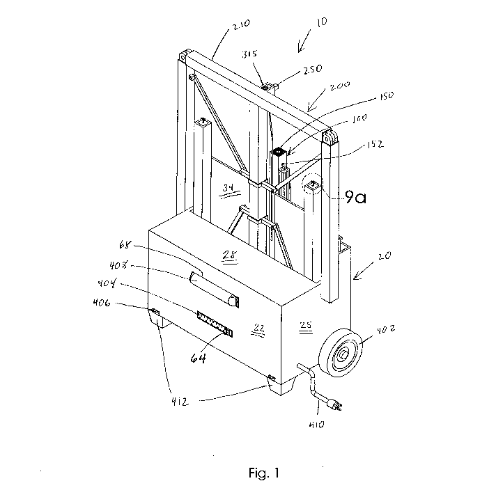
Fig. 1 is a perspective view of a mobile sheltered workstation according to
a preferred embodiment of the present invention illustrating a main support
member
in a retracted configuration, a canopy framework in a stowed configuration,
and
omitting a canopy from the view;
Fig. 2 is a perspective view of the mobile sheltered workstation, as in Fig.
1, illustrating the canopy framework in a deployed configuration with a pair
of first
arms and a pair of second arms in a stowed and retracted configuration and a
main
support brace in a retracted configuration;
Fig. 3 is a perspective view of the mobile sheltered workstation, as in Fig.
2, illustrating respective pairs of the first and second arms in a deployed
and
extended configuration and the main support brace in an extended
configuration;
Fig. 4a is a perspective view of the mobile sheltered workstation, as in Fig.
3, illustrating the main support member in an extended configuration;
Fig. 4b is an isolated view on an enlarged scale taken from Fig. 4a showing
a pair of springable flanges in a compressed configuration;
Fig. 5 is a perspective view of the mobile sheltered workstation, as in Fig.
4, illustrating the canopy selectively coupled to the canopy framework, a
plurality
of tie down cables, each one selectively coupled to the canopy framework, and
a
plurality of tie down stakes, each one selectively coupled to one of the tie
down
cables;
3a
CA 2959720 2018-07-03
CA 02959720 2017-03-01
WO 2015/034781 PCT/US2014/053473
Fig. 6a is a side elevation view of the mobile sheltered workstation with the
canopy and canopy framework omitted from the view and the main support
member in the extended configuration;
Fig. 6b is a sectional view taken along line 6b-6b of Fig. 6a;
Fig. 7 is an isolated view on an enlarged scale taken from Fig. 6b;
Fig. 8 is a perspective view of an electrical power strip removed from the
housing;
Fig. 9a is an isolated view on an enlarged scale taken from Fig. 1 showing a
pair of springable flanges in an uncompressed configuration;
Fig. 9b is an isolated view on an enlarged scale taken from Fig. 5;
Fig. 10a is a side elevation view of the mobile sheltered workstation, as in
Fig. 4;
Fig. 10b is an isolated view on an enlarged scale taken from Fig. 10a;
Fig. 10c is an isolated view on an enlarged scale taken from Fig. 10a;
Fig. Ila is a perspective view of the mobile sheltered workstation, as in Fig.
4, shown from a different angle than Fig. 4;
Fig. 1 lb is an isolated view on an enlarged scale taken from Fig. 11a;
Fig. 11c is an isolated view on an enlarged scale taken from Fig. 11a;
Fig. 12 is a perspective view of the mobile sheltered workstation, as in Fig.
1, shown from a different angle than Fig. 1;
Fig. 13a is a side elevation view of the mobile sheltered workstation with
the canopy and canopy framework omitted from the view and the main support
member in the extended configuration;
Fig. 13b is a sectional view taken along line 13b-13b of Fig. 13a.
4
CA 02959720 2017-03-01
WO 2015/034781 PCT/US2014/053473
DESCRIPTION OF THE PREFERRED EMBODIMENT
A mobile sheltered workstation according to a preferred embodiment of the
present invention will now be described with reference to Figs. 1 to 13b of
the
accompanying drawings. The mobile sheltered workstation 10 includes a housing
20, a main support member 100, and a canopy framework 200. The mobile
sheltered workstation 10 may also include a canopy 50 selectively coupled to
the
canopy framework 200, a plurality of tie down cables 360 selectively coupled
to
the canopy framework 200 and/or a plurality of tie down stakes 362 selectively
coupled to the tie down cables 360.
The housing 20 may include opposed front 22 and rear 24 exterior walls
with opposed side exterior walls 25 extending between respective ends of the
front
22 and rear 24 exterior walls, respectively. Accordingly, the housing 20 may
present a generally square or rectangular configuration although other
configurations may also be suitable.
The housing 20 may also include a bottom panel 26 extending between
respective side exterior walls 25 and respective front 22 and rear 24 exterior
walls
such that the walls and bottom panel 26 together define an interior area 30.
The
interior area 30 of the housing 20 may be bisected by opposed front 32 and
rear 34
interior walls so as to create a second area 40 located within the interior
area 30.
The housing 20 may also include a top panel 28 extending between respective
side
exterior walls 25, the front exterior wall 22, and the front interior wall 32.
Accordingly, the configuration of the housing 20 may provide separate
compartments suitable for storage of tools, equipment, the canopy framework
200,
the canopy 50, the tie down cables 360, and/or the tie down stakes 362. (Fig.
1 and
Fig. 12). In one embodiment, the front 32 and/or rear 34 interior walls may be
omitted so as to provide different sizes and configurations of storage
compartments.
A pair of wheels 402 may be rotatably coupled to opposed side exterior
walls 25 of the housing 20 (Fig. 12). It is understood that each wheel 402 may
be
CA 02959720 2017-03-01
WO 2015/034781 PCT/US2014/053473
independently rotatably coupled to a respective side exterior wall 25 or that
both
wheels 402 may be coupled to one another by an axle that is coupled to the
housing 20. A pair of legs 412 may be coupled to the housing 20 and positioned
relative to the wheels 402 such that the combination of wheels 402 and the
legs
412 creates a stable support structure for the housing 20. A plurality of tie
down
attachments 406 may be coupled to the housing 20 such that the housing 20 may
be staked directly to the ground to provide added stability to the mobile
sheltered
workstation 10 when at a deployed configuration.
The front exterior wall 22 may define a first aperture 64 and a second
aperture 68. An electrical power strip 404 may be situated within the interior
area
30 and configured to register with the first aperture 64. Accordingly, the
electrical
power strip 404 is located at least partially in the interior area 30 of the
housing 20
and is operatively accessible from an area outside the housing 20. A light 408
may
be configured to register with the second aperture 68 such that the light 408
is
located at least partially in the interior area 30 of the housing 20 and is
configured
to allow the light 408 to illuminate an area outside of the housing 20.
Additionally,
a power cord 410 may be located at least partially in the interior area 30 of
the
housing 20 and configured to connect to an exterior power source. It is
understood
that inclusion and/or positioning of the electrical power strip 404 and/or the
light
408 may vary.
The main support member 100 includes a lower end 102 coupled to the
housing 20 and extending upwardly therefrom. The main support member 100 may
be length adjustable and telescopically movable between a retracted
configuration
(Fig. 3) and an extended configuration (Fig. 4a). More particularly, the main
support member 100 may include a plurality of main support member sections 110
configured to nest within the main support member 100 at the retracted
configuration and to incrementally extend upwardly from the main support
member 100 at the extended configuration.
6
CA 02959720 2017-03-01
WO 2015/034781 PCT/US2014/053473
Each main support member section 110 may be configured so as to be
secured at selected positions when the main support member 100 is at the
extended
configuration. Each main support member section 110 may define at least one
hole
120 configured to receive a pin 122 so as to hold the plurality of main
support
member sections 110 at respective selected positions when respective holes 120
in
respective main support member sections 110 receive respective pins 122. It is
understood that each main support member section 110 may define a plurality of
holes 120 so as to provide a variety of selectable positions.
The plurality of main support member sections 110 may include at least a
first support member section iii and a second support member section 112. A
pin
122 may be coupled to the first main support member section 111. A spring 124
may be coupled to the pin 122 so as to bias the pin 122 towards the second
support
member section 112 such that the pin 122 couples the first support member
section
111 to the second support member section 112 by engaging respective holes 120
in
the first 111 and second 112 support member sections, respectively (Fig. 7).
The canopy framework 200 may be moved between a stowed configuration
(Fig. 1) and a deployed configuration (Fig. 4a). Accordingly, the canopy
framework may include a lower end 204 having an attachment flange 250
configured to selectively couple to an upper end 104 of the main support
member
100. The upper end 104 of the main support member 100 may define an
attachment bore 150 configured to receive the attachment flange 250 of the
canopy
framework 200. The upper end 104 of the main support member 100 may further
define a locking hole 152 configured to receive a locking pin (not shown) so
as to
lock the canopy framework 200 to the main support member 100 when the
attachment flange 250 of the canopy framework 200 is received by the
attachment
bore 150 of the main support member 100. The canopy framework 200 is generally
adjacent the housing 20 at the stowed configuration (Fig. 1) and displaced
from the
housing 20 at the deployed configuration (Fig. 4a).
7
CA 02959720 2017-03-01
WO 2015/034781 PCT/US2014/053473
The canopy framework 200 may also include a main support brace 230
having a first end 231 and a second end 232. The main support brace 230 may be
length adjustable and telescopically movable between a retracted configuration
(Fig. 2) and an extended configuration (Fig. 3) so as to coincide with the
stowed
and deployed configurations of the canopy framework 200, respectively.
The canopy framework 200 may also include a first support brace 210
coupled to the first end 231 of the main support brace 230 and/or a second
support
brace 220 coupled to the second end 232 of the main support brace 230. In one
embodiment, the first support brace 210 may be fixedly coupled to the first
end
231 of the main support brace 230 and the attachment flange 250 may be coupled
to the first support brace 210. Consequently, the first support brace 210 of
the
canopy framework 200 may be removably coupled to the upper end 104 of the
main support member 100 when the attachment flange 250 of the canopy
framework 200 is received by the attachment bore 150 of the main support
member 100. It is understood that, in another embodiment, the attachment
flange
250 may be coupled to the main support brace 230 and/or the second support
brace
220.
The canopy framework 200 may also include a pair of first arms 212
coupled to opposed ends of the first support brace 210, respectively. Each one
of
the pair of first arms 212 may be movable between a stowed configuration (Fig.
2)
and a deployed configuration (Fig. 3). Each one of the pair of first arms 212
may
be generally parallel to the main support brace 230 when at the stowed
configuration and generally perpendicular to the main support brace 230 when
at
the deployed configuration.
The pair of first arms 212 may be pivotally coupled to opposed ends of the
first support brace 210, respectively, so as to enable the pair of first arms
212 to
rotatably move from the stowed configuration to the deployed configuration.
Additionally, each one of said pair of first arms 212 may be length adjustable
and
telescopically movable between a retracted configuration (Fig. 2) and an
extended
8
CA 02959720 2017-03-01
WO 2015/034781 PCT/US2014/053473
configuration (Fig. 3) so as to coincide with the stowed and deployed
configurations of the canopy framework 200, respectively.
The canopy framework 200 may further include a first linkage assembly
310 operatively coupled to the pair of first arms 212 and the main support
brace
230. More particularly, the first linkage assembly 310 may include a first
collar
314 slidably coupled to the main support brace 230. The first linkage assembly
310
may also include a pair of first deployment members 312 extending between the
first collar 314 and the pair of first arms 212, respectively, such that the
pair of
first arms 212 is rotated between a stowed configuration and a deployed
configuration when the first collar 314 is slidably moved along the main
support
brace 230.
In one embodiment, the first linkage assembly 310 may include a pair of
first collars 314, each of the pair of first collars 314 being slidably
coupled to one
of the pair of first arms 212, and a pair of first deployment members 312
extending
between the main support brace 230 and the pair of first collars 314,
respectively,
such that each of the pair of first arms 212 may be rotated between a stowed
configuration and a deployed configuration when a respective first collar 314
is
slidably moved along the respective first arm 212.
In yet another embodiment, the first linkage assembly 310 may include a
pair of first deployment members 312 coupled to the main support brace 230 and
the pair of first arms 212, respectively, so as to hold the pair of first arms
212 in a
stowed configuration ancUor a deployed configuration. Each of the pair of
first
deployment members 312 may be removable, may be bisected with a pivot joint
(not shown) so as to operate as a hinge, and/or may be length adjustable and
telescopically movable between a retracted configuration and an extended
configuration.
The canopy framework 200 may further include a first pulley assembly 315
having a first pulley 316. A first cord 318 may be selectively coupled to the
first
pulley 316 and the first linkage assembly 310 so as to cause the first collar
3 14 to
9
CA 02959720 2017-03-01
WO 2015/034781 PCT/US2014/053473
slidably move along the main support brace 230 when tension is exerted upon
the
first cord 318. With this construction, operation of the first pulley assembly
315
enables a user to move the pair of first arms 212 between stowed and deployed
configurations by pulling on the first cord 318.
The canopy framework 200 may also include a pair of second arms 222
coupled to opposed ends of the second support brace 220, respectively. Each
one
of the pair of second arms 222 may be movable between a stowed configuration
(Fig. 2) and a deployed configuration (Fig. 3). Each one of the pair of second
arms
222 may be generally parallel to the main support brace 230 when at the stowed
configuration and generally perpendicular to the main support brace 230 when
at
the deployed configuration. Consequently, the pair of second arms 222 may be
generally parallel to and displaced from the pair of first arms 212 when the
respective pairs of first 212 and second 222 arms are at the deployed
configuration.
Additionally, the pair of second arms 222 may be generally parallel and
adjacent to
the pair of first arms 212 when the respective pairs of first 212 and second
222
arms are at the stowed configuration. Respective first 210 and second 220
support
braces and/or respective pairs of first 212 and second 222 arms may be
configured
so as to allow the pair of second arms 222 to nest inside of the pair of first
arms
212 when respective pairs of first 212 and second 222 arms are at the stowed
configuration (as best shown in Fig. 2).
The pair of second arms 222 may be pivotally coupled to opposed ends of
the second support brace 220, respectively, so as to enable the pair of second
arms
222 to rotatably move from the stowed configuration to the deployed
configuration
as will be described more fully below. Additionally, each one of said pair of
second arms 222 may be length adjustable and telescopically movable between a
retracted configuration (Fig. 2) and an extended configuration (Fig. 3) so as
to
coincide with the stowed and deployed configurations of the canopy framework
200, respectively.
CA 02959720 2017-03-01
WO 2015/034781 PCT/US2014/053473
The canopy framework 200 may further include a second linkage assembly
320 coupled to the pair of second arms 222 and the main support brace 230. The
second linkage assembly 320 may include a second collar 324 slidably coupled
to
the main support brace 230. The second linkage assembly 320 may also include a
pair of second deployment members 322 extending between the second collar 324
and the pair of second arms 222, respectively, such that the pair of second
arms
222 is rotated between a stowed configuration and a deployed configuration
when
the second collar 324 is slidably moved along the main support brace 230.
In one embodiment, the second linkage assembly 320 may include a pair of
second collars 324, each of the pair of second collars 324 being slidably
coupled to
one of the pair of second arms 222, and a pair of second deployment members
322
extending between the main support brace 230 and the pair of second collars
324,
respectively, such that each of the pair of second arms 222 is rotated between
a
stowed configuration and a deployed configuration when the respective second
collar 324 is slidably moved along the respective second arm 222.
The second linkage assembly 320 may also include a pair of second
deployment members 322 coupled to the main support brace 230 and the second
pair of arms 222, respectively, so as to hold the second pair of arms 222 in a
stowed configuration and/or a deployed configuration. Each of the pair of
second
deployment members 322 may be removable, may be bisected with a pivot joint
(not shown) so as to operate as a hinge, and/or may be length adjustable and
telescopically movable between a retracted configuration and an extended
configuration.
The canopy framework 200 may further include a second pulley assembly
325 having a second pulley 326. A second cord 328 may be selectively coupled
to
the second pulley 326 and the second linkage assembly 320 so as to cause the
second collar 324 to slidably move along the main support brace 230 when
tension
is exerted upon the second cord 328. With this construction, operation of the
11
CA 02959720 2017-03-01
WO 2015/034781 PCT/US2014/053473
second pulley assembly 325 enables a user to move the pair of second arms 222
between stowed and deployed configurations by pulling on the second cord 328.
The canopy framework 200 may also include a plurality of canopy
attachment mechanisms 350 and the canopy 50 may include a plurality of canopy
attachment elements 55. Each canopy attachment mechanism 350 of the canopy
framework 200 may be configured to interface with one or more canopy
attachment element 55 of the canopy 50. Each canopy attachment element 55 of
the canopy 50 may be a grommet.
The canopy attachment mechanism 350 may include opposed springable
flanges 352 that are selectively movable between compressed and uncompressed
configurations. The springable flanges 352 may be configured so as to allow a
canopy attachment element 55 of the canopy 50 to slide over the springable
flanges 352 of one of the canopy attachment mechanisms 350 when the springable
flanges 352 of the canopy attachment mechanism 350 are at the compressed
configuration. Consequently, the canopy 50 may be coupled to or decoupled from
the canopy framework 200 by sliding respective canopy attachment elements 55
of
the canopy 50 over springable flanges 352 of respective canopy attachment
mechanisms 350 of the canopy framework 200. Additionally, the springable
flanges 352 may be configured so as to prevent respective canopy attachment
elements 55 of the canopy 50 from sliding over springable flanges 352 of
respective canopy attachment mechanisms 350, thereby preventing the canopy 50
from decoupling from the canopy framework 200.
In one embodiment, the canopy 50 may include one set of canopy
attachment elements 55 so as to selectively couple to the canopy framework 200
to
cover a predetermined geometric area. In another embodiment, the canopy 50 may
include multiple sets of canopy attachment elements 55 so as to selectively
couple
to the canopy framework 200 to cover a variety of geometric areas. It is
understood that the canopy my also include a rain shield cover positioned over
each canopy attachment element so as to prevent leakage through the canopy.
12
CA 02959720 2017-03-01
WO 2015/034781 PCT/US2014/053473
The canopy framework 200 may be adjustable to accommodate different
canopy 50 sizes to accommodate different shelter requirements such as when
high
winds at or obstacles near a worksite prevent the use of a large canopy 50 or
when
a large worksite requires the use of a large canopy. The main support brace
230
and/or the first 212 and second 222 pairs of arms may be extendable and/or
retractable to accommodate different canopy 50 lengths and/or widths.
Additionally, respective pairs of first 212 and second 222 arms may be
rotatable to
provide additional flexibility for accommodating different canopy 50 sizes.
The canopy framework 200 may be adjustable to accommodate different
canopy 50 shapes to accommodate different shelter requirements such as when
obstacles near a worksite require the use of a canopy 50 with a shape other
than the
rectangular shape shown in the drawings. The main support brace 230 and/or the
first 212 and second 222 pairs of arms may be extendable and/or retractable to
accommodate different canopy 50 shapes. Additionally, respective pairs of
first
212 and second 222 arms may be rotatable to provide additional flexibility for
accommodating different canopy 50 shapes.
The canopy framework 200 may be adjustable to accommodate different
canopy 50 tension requirements to accommodate different shelter requirements,
such as to tighten the canopy during high winds or to allow the canopy to
droop on
one or more sides to divert rain water from a worksite. The main support brace
230
and/or the first 212 and second 222 pairs of arms may be extendable and/or
retractable to accommodate different canopy 50 tension requirements.
Additionally, respective pairs of first 212 and second 222 arms may be
rotatable to
provide additional flexibility for accommodating different canopy 50 tension
requirements.
In use, the mobile sheltered workstation 10 provides a person with a mobile
worksite shelter. It should be appreciated that the main support member 100
and
the canopy framework 200 may be stored in the back of a truck or van ¨ so as
to
provide easier transportation to and from a worksite - when they are at
retracted
13
CA 02959720 2017-03-01
WO 2015/034781 PCT/US2014/053473
and stowed configurations, respectively. Upon arrival at the worksite, a
canopy 50
may be coupled to the canopy framework 200 and the main support member 100
and the canopy framework 200 may be coupled together and moved to extended
and deployed configurations, respectively, so as to create a quick and
convenient
shelter at the worksite. Further, an electrical power strip 404 may provide
safe and
convenient access to electricity at the worksite and a light 408 may
illuminate the
worksite.
It is understood that while certain forms of this invention have been
illustrated and described, it is not limited thereto except insofar as such
limitations
are included in the following claims and allowable functional equivalents
thereof.
14