Note: Descriptions are shown in the official language in which they were submitted.
1
TITLE: "Crane for lifting and transporting loads comprising a
roll-over protection system"
***
DESCRIPTION
Technical field
The present invention relates to a crane, or equipment,
for lifting and moving loads, equipped with an implemented
roll-over protection system.
Technological background
In the industrial field, as well as in the craft
industry, the need to pick up, move and position loads, even
considerably heavy ones, to/at substantial heights and
distances from the pick-up point is well known.
However, due to the considerable weight of the load to
be moved, as well as the distance between said load and the
crane, the crane is in danger of rolling over, consequently
posing risks to the people in its vicinity and to the goods.
Furthermore, during the moving of loads, there is a high risk
of dynamic roll-over due to the abrupt movements of certain
parts of the crane itself.
Therefore, the need is felt to provide cranes for
lifting and moving loads, which are equipped with an
implemented roll-over protection system and are able to
intervene in a prompt, precise and safe manner.
Summary of the invention
An object of the present invention is to provide a crane
for lifting and moving loads, equipped with a roll-over
protection system, which is able to solve this and other
drawbacks of the prior art and which, at the same time, can
be produced in a simple and economic fashion.
Date Recue/Date Received 2020-09-25
la
According to a general aspect, there is provided a crane
for lifting and transporting loads, the crane comprising a
base frame, for transferring the loads of the crane onto a
support surface by means of contact means arranged in contact
with said support surface; a lifting mechanism to lift and
transport the loads, associated with said base frame; and a
roll-over protection system comprising: a first portion and a
second portion of the base frame, mutually hinged to one
another and capable of rotating around a hinge, the first and
second portions being also constrained by at least one
elastic means, a deformation of said at least one elastic
means being linked to a mutual angular position of the first
and second portions; wherein the lifting mechanism is
associated with only one of the first second portions; at
least one sensor; and a control system for detecting, via
said at least one sensor, the mutual position between the
first and second portions, and carrying out predetermined
tasks of the crane when said mutual position reaches a
threshold condition; said at least one sensor being
associated with at least one of the first and second
portions.
Other possible aspect(s), object(s), embodiment(s),
variant(s) and/or advantage(s) of the present invention, all
being preferred and/or optional, are briefly summarized
hereinbelow.
In particular, one of the technical problems solved by
the present invention is that of providing a crane for
Date Recue/Date Received 2022-01-05
CA 02960065 2017-03-02
W02016/038525
PCT/IB2015/056823
2
lifting and moving loads, equipped with an implemented
roll-over protection system, which is able to intervene in
a prompt, precise and safe manner.
One particular variant of the invention has the object
of providing a crane for lifting and moving loads, capable
of performing a wide range of movements.
According to the present invention, this and other
objects are reached by means of a crane having the features
set forth in the appended independent claim.
The appended claims are an integral part of the
technical teaches provided in the following detailed
description concerning the present invention. In
particular, the appended dependent claims define some
preferred embodiments of the present invention and describe
optional technical features.
Brief description of the drawings
Further features and advantages of the present
invention will be best understood upon perusal of the
following detailed description, which is provided by way of
example and is not limiting, with reference, in particular,
to the accompanying drawings, wherein:
- figure 1 is a lateral view of a crane according to an
embodiment of the present invention;
- figure 2 is a lateral view of a crane according to the
invention, shown in different operating conditions;
- figure 3 is a plan view of a crane according to the
invention;
- figure 4 is a lateral view of a detail of the crane;
- figure 5 is a plan view of a further detail of the
crane;
- figure 6 is a front view of a further detail of the
crane;
CA 02960065 2017-03-02
W02016/038525
PCT/IB2015/056823
3
- figure 7 is a lateral view of a crane according to a
further embodiment of the present invention.
Detailed description of the invention
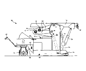
With reference to the accompanying figures, number 10
indicates, as a whole, a crane for lifting and moving
loads, comprising:
- a base frame 12, capable of transferring the loads of
crane 10 onto a support surface by means of contact means
arranged in contact with said surface, such as wheels 14;
- a lifting
mechanism to lift and transport loads,
associated with said base frame (12);
Crane 10 is also equipped with a roll-over protection
system comprising:
- a first portion (36) and a second portion (38) of base
frame (12), mutually hinged to one another, the first (36)
and the second portion (38) being also constrained by at
least one elastic means (40); and
- a control system adapted for detecting the mutual
position between the first (36) and the second portion (38)
and of carrying out predetermined tasks of crane (10) when
said mutual position reaches a threshold condition.
For greater clarity, a non-limiting description of a
crane 10 having a particular structure and a preferred
lifting mechanism is provided below.
With particular reference to the variant shown in
figures from 1 to 6, crane 10 comprises:
- babe frame 12;
- a sliding element 16 which is constrained to base
frame 12 in a sliding manner;
- an arm 18,
adapted for moving the loads and is hinged
to the sliding element 16;
- a connection element 20 having a first end, which is
CA 02960065 2017-03-02
W02016/038525
PCT/IB2015/056823
4
hinged to sliding element 16, and a second end, which is
constrained to base frame 12 in a mobile manner;
- a pair of rod elements 22, each rod element 22 being
hinged to said base frame 12 and to said connection element
20 so as to form an articulated quadrilateral;
- a first linear actuator 24, hinged to base frame 12
and to connection element 20 and s able to cause the
sliding movement of sliding element 16 relative to base
frame 12;
- a second
linear actuator 26, hinged to sliding element
16 and to arm 18 and is able to cause the mutual rotation
movement between arm 18 and sliding element 16.
In a non-limiting manner, figure 1 shows an
articulated quadrilateral, which is defined by the points
indicated with letters A, B, C, D.
In the preferred variant shown in figure 1, sliding
element 16 is adapted to slide substantially vertically.
In particular, base frame 12 comprises a pair of
uprights 28, which are provided with guides, on which the
sliding element 16 is designed to slide.
In the example, arm 18 and sliding element 16 are
longitudinal elements; conveniently, they are beam
elements, preferably internally hollow.
Sliding element 16 is arranged along a substantially
vertical line and, in correspondence to its upper end, it
is hinged to arm 18. Therefore, arm 18 and sliding element
16 are suited to mutually rotate. In the preferred example
shown, sliding element 16 is able to perform a vertical
sliding motion relative to base frame 12, and arm 18 is
able to rotate relative to said sliding element 16.
Consequently, arm 18 is able to perform a rotational-
translational motion, thus allowing crane 10 to have ample
CA 02960065 2017-03-02
W02016/038525
PCT/IB2015/056823
freedom of movement.
With particular reference to the constraint between
sliding element 16 and arm 18, the term "hinged" should not
be understood in a limiting way: i.e. sliding element 16
5 and arm 18 can be connected by means of a through pin, but,
alternatively, they can also be constrained by means of any
hinge system suited to allow them to mutually rotate. A
similar observation applies to the other hinge constraints
to be found in crane 10.
Conveniently, arm 18 is telescopic.
With reference to a particular variant that is not
shown herein, arm 18 is telescopic and comprises three
mutually sliding segments, which are controlled by a third
linear actuator. The first segment is constrained to the
sliding element in a rotary manner, the second segment can
slide relative to the first segment, and the third segment
can slide relative to the second segment. The third linear
actuator is adapted to perform the extraction/retraction of
the segments, so as to increase/decrease the reach of arm
18. In this way, loads can also be moved to considerable
distances from the point where crane 10 is located, while
ensuring a high degree of compactness of crane 10 itself.
Conveniently, hydraulic actuators 24, 26, or at least
one of them, are hydraulic jacks mainly consisting of a
piston sliding inside a cylinder.
Preferably, arm 18 is provided with means for
attaching and transporting the loads, such as, for example,
a clamp, tongs, a hook 30, or a platform, etc.
For example, arm 18 is associated with a winch system
or a hoist, in order to move the loads. Said winch is
conveniently activated by a motor means, such as an
electric motor.
CA 02960065 2017-03-02
W02016/038525
PCT/IB2015/056823
6
The winch (or hoist) is associated with a hook 30, or
the like, which can be extracted or retracted by operating
the winch.
According to a variant which is not shown herein, arm
18 comprises a pair of hooks: the first hook is controlled
by a winch and is therefore mobile, or extractable,
relative to arm 18; the second hook, on the other hand, is
fixed with respect to arm 18. In particular, the first and
the second hook can be placed on the distal end of the
telescopic segment of arm 18.
According to further variants, arm 18 can only be
associated with one or more fixed hooks. Furthermore, the
point in which the hooks, either fixed or extractable, are
associated with arm 18 in the following examples should not
be understood in a limiting way. For example, it is
possible that the fixed hook is attached to the first or
the second segment and is therefore not to be found on the
distal end of arm 18. Furthermore, it is possible to
associate the at least one hook with a non-telescopic arm
18 as well.
With a non-limiting reference to the variant shown in
figure 1, connection element 20 is manufactured by means of
a pair of plates, among which an end of the first linear
actuator 24 is hinged (in particular the upper end), and
each plate is associated with a respective pair of rod
elements 22 so as to create an articulated quadrilateral
with the respective plate 20 and base frame 12.
In particular, base frame 12 comprises a pair of
uprights 28, and each upright 28 is connected in a mobile
manner to the respective plate 20 by means of the
respective pair of rod elements 22. Therefore, in the
example shown, there are two uprights 28 belonging to base
CA 02960065 2017-03-02
W02016/038525
PCT/IB2015/056823
7
frame 12, two plates making up the connection element 20,
and four rod elements 22.
This preferred embodiment allows some of the mobile
elements suited to lift and move the load to partially
interlock with each other, thus combining a high load
capacity and a wide range of movements in a remarkably
compact structure.
The lower end of the first linear actuator 24 is
hinged to the lower part of base frame 12 and said first
linear actuator 24 is mainly located between the two
uprights 28. The first linear actuator 24 is also located
between the two pairs of rod elements 22 and between the
two plates making up connection element 20. In this
configuration, which represents a preferred non-limiting
variant of the invention, crane 10 gains remarkable
compactness.
Generally, the two plates making up connection element
are mutually constrained by means of structural elements
such as connection brackets or the like. Conveniently, a
20 tubular element or a pin is fixed between the plates, the
upper end of the first linear actuator 24 being pivoted on
said tubular element or pin.
In the variant shown herein, the two plates 20 are
arranged laterally with respect to sliding element 16,
close to the point where they are hinged to said sliding
element 16.
Figure 2 shows a variant of crane 10 in four- different
operating conditions.
In the first operating condition, arm 18 is in a
lowered position and is arranged horizontally, and one can
see other mobile elements, among which rod elements 22,
connection element 20, sliding element 16 and linear
CA 02960065 2017-03-02
W02016/038525
PCT/IB2015/056823
8
actuators 24, 26.
In the second operating condition, arm 18r is in a
lowered and inclined position.
In the third operating condition, arm 18' is in a
lifted position and is arranged horizontally, and one can
see other mobile elements, among which rod elements 22',
connection element 20', sliding element 16' and linear
actuators 24', 26'. In this lifted condition, C' and D'
indicate the points that, together with A and B, make up
the articulated quadrilateral. Indeed, points A and B are
fixed with respect to base frame 12 (in particular A and B
belong to uprights 28), while points C, C' and D, D' are
mobile and represent the point where rod element 22 is
hinged to connection element 20.
In the fourth operating condition, arm 18'r is in a
lifted and inclined position.
As already mentioned above, in order to move arm 18
from lowered condition (18, 18r) to the lifted one (18',
18'r) and vice versa, the first linear actuator 24 is used;
whereas in order to allow arm 18 to tilt, the second linear
actuator 26 is used.
In the figure, 18t schematically indicates the
telescopic segment of arm 18.
Preferably, crane 10 comprises a ground drive
transmission means to transmit the drive to the ground,
which is controlled by a rudder 32, conveniently a servo-
assisted one. The ground drive transmission means can
comprise a driving wheel 34, or a track, or any other means
suited to transmit a driving force onto a support surface.
For example, figure 6 shows a preferred ground drive
transmission means comprising a pair of driving wheels 34,
which are conveniently able to rotate independently of one
CA 02960065 2017-03-02
W02016/038525
PCT/IB2015/056823
9
another. This solution turns out to be particularly
advantageous when steering, since the presence of a pair of
wheels 34, compared to a single wheel, brings about a
reduction in the friction force arising between wheels 34
and the ground and obstructing the steering.
The pair of wheels 34 is supported by a support
structure 44 associated with base frame 12 in a rotary
manner, in particular it is associated with the first
portion 36. For the sake of simplicity, in the remaining
part of the description, reference is made to driving wheel
34, nonetheless without limiting the inventive concept.
The servo-assistance of the steering gear can be of a
known type, and it is useful to reduce the force that needs
to be exerted by a user who intends to steer the wheel
manually by holding the rudder, thus making the crane
easier to use, especially when the weight of the crane and
of the supported load amounts to a few tons, in which case
the friction force of the wheel on the ground would make it
difficult for a user to steer only manually. In the example
shown in figures 3 and 6, on the first portion 36 there is
a steering linear actuator 46, for example a hydraulic
jack, which acts upon support structure 44, allowing it to
rotate relative to base frame 12. Steering linear actuator
46 acts upon support structure 44 by means of a gear 52
which is associated with base frame 12. Alternatively,
steering linear actuator 46 can be directly constrained (in
particular by means of a hinge) to support structure 44; or
it can be connected to support structure 44 by means of
further mechanisms.
Preferably, rudder 32 is equipped with a plurality of
control tools to control the movement of crane 10 and the
movements of the "lifting mechanism" comprising arm 18,
CA 02960065 2017-03-02
W02016/038525
PCT/1B2015/056823
sliding element 16, rod elements 22, connection element 20.
By using the control tools it is possible to control the
activation of linear actuators 24, 26, and, if necessary,
of the third linear actuator. By using the control tools it
5 is also possible, if necessary, to control the activation
of the means for attaching and transporting the loads, such
as extractable hook 30, etc.
The control tools can comprise, for example, push-
buttons, levers, screens, warning lights, sirens,
10 indicators of different types, thus allowing the user to
receive signals of various kinds regarding the operation of
crane 10.
According to a preferred embodiment of the present
invention, crane 10 comprises a wireless remote control
system, adapted for controlling the movement of arm 18
and/or the movement of ground drive transmission means 34.
In the further advantageous variant in which the remote
control system is suited to control both the movement of
arm 18 and the movement of driving wheel 34, the operator
can operate in a totally remote manner by remaining at a
distance from crane 10 during the movement of the crane
itself on the supporting ground, as well as during the
moving of the loads. By so doing a higher degree of safety
is achieved, due to the fact that the user does not have to
remain in contact with crane 10 while performing all the
operations anymore, in particular when it is necessary to
operate in dangerous situations, such as unsafe
environments where there may be falling objects, the
presence of high temperature objects, the presence of
harmful substances, etc.
The roll-over protection system will now be described
in detail, with a non-limiting reference to the examples
CA 02960065 2017-03-02
W02016/038525
PCT/IB2015/056823
11
shown and explained herein.
As already mentioned above, the control system is
capable of detecting the mutual position between the first
36 and the second portion 38 and of carrying out
predetermined tasks of the crane when said mutual position
reaches a threshold condition.
For example, arm 18 of crane 10 is telescopic and,
when the mutual position reaches the threshold condition,
the control system prevents telescopic arm 18 from
extending or moving.
With particular reference to figures from 3 to 5, the
roll-over protection system comprises a pair of elastic
means (in the example, springs) 40, each connected to the
first 36 and to the second portion 38 of base frame 12.
Preferably, crane 10 comprises at least one sensor (a
sensor means, or the like) capable of detecting the mutual
position between said portions 36, 38. The at least one
sensor is conveniently associated with the first 36 and/or
the second portion 38 of the base frame.
With reference to the variant shown, a sensor 48 is
advantageously used, which is associated with one of said
portions (in the example, said sensor is associated with
the first portion 36) adapted to detect the proximity to or
the contact with the other portion (in particular, the
second portion 38). Sensor 48 is preferably a contact
sensor or a proximity sensor (e.g. a photodetector, a
sensor of the capacitive, inductive, magnetic, ultrasound
or optical type, etc.).
On the second portion 38 there is a striker portion 50
adapted to cooperate with sensor 48, so as to signal the
mutual position between the first 36 and the second portion
38. Alternatively, crane 10 can be provided with further
CA 02960065 2017-03-02
WO 2016/038525
PCT/1B2015/056823
12
known types of sensors, to be arranged on the first 36
and/or second portion 38 of base frame 12, designed to
detect the mutual position between said portions.
According to a particular variant, the detection of
the mutual position between the first 36 and the second
portion 38 is carried out by means of the detection of the
deformation of elastic means 40. Indeed, since the first 36
and the second portion 38 are constrained by means of at
least one hinge (in the figure, number 42 indicates, by way
of example, the hinging point, which from now on will also
be called "hinge" for the sake of brevity) and at least one
elastic means 40, the deformation of elastic means 40 is
linked to the position of the first 36 and second portion
38, which are capable of rotating around the hinging point
42. With a non-limiting reference to figures from 1 to 4,
hinge 42 is located in the lower part of base frame 12 and
elastic means 40 is located in an upper part; therefore,
the two portions 36, 38 of base frame 12 are constrained to
rotate around hinging point 42, and said rotation
corresponds to a greater or smaller elongation of elastic
means 40. Therefore, by measuring the deformation of
elastic means 40, it is possible to detect the mutual
position between the first 36 and the second portion 38.
In general, when the mutual position between the first
36 and the second portion 38 reaches a threshold condition,
or a threshold value, the control system can be suited to
carry out many and different predetermined tasks, such as
for example: stopping one or more linear actuators 24, 26,
46; performing one or more predetermined movements of at
least one linear actuator 24, 26, 46; interrupting the
operation of driving wheel 34; emitting an emergency signal
that can be perceived by a user (e.g. light and/or sound
CA 02960065 2017-03-02
W02016/038525
PCT/1B2015/056823
13
signal), etc.
In general, the control system can be designed in such
a way that, when the mutual position between the first 36
and the second portion 38 reaches a threshold value, every
movement of crane 10 that is likely to cause an increase in
the rolling-over torque is interrupted or inhibited. The
control system can also be designed in such a way that,
when the mutual position between the first 36 and the
second portion 38 reaches a threshold value, one or more
movements of crane 10 that are likely to cause a decrease
in the rolling-over torque are carried out.
By mere way of example, a description follows of how
the roll-over protection system operates with reference to
the variant of crane 10 shown. During the load moving
operations, telescopic arm 18 supports a load at its ends;
depending on the extension of said arm 18, a rolling-over
torque is generated relative to the support base of crane
10 - in the example shown, the support base is made up of
the support wheels 14 and driving wheel 34. Therefore, when
the extension of arm 18 generates a rolling-over torque
having a limit value, the crane is in danger of rolling
over, consequently posing risks to the health of the people
in its vicinity, to the integrity of the goods and of the
surrounding environment. Based on the rolling-over torque
(depending on the weight of the load and the reach of
telescopic arm 18), the contact means arranged in contact
with the support surface (in this specific case, wheels 14
and driving wheel 34) generate a constraining reaction with
respect to the support surface; as the rolling-over torque
changes, the constraining reaction of wheels 14, 34 changes
accordingly, so as to generate a stabilizing torque which
is equal to and opposite to the rolling-over one.
CA 02960065 2017-03-02
W02016/038525
PCT/1B2015/056823
14
Therefore, based on the constraining reactions of the
different contact means, the mutual position between the
first 36 and the second portion 38 of base frame 12 will
change, since the first and the second portion are mutually
constrained by means of a hinge 42 and an elastic means 40.
As a consequence, when the rolling-over torque assumes a
predetermined limit value, or a danger one, which
corresponds to a mutual position between the first 36 and
the second portion 38, the control system detects said
mutual position and, if the mutual position reaches a
threshold condition, or a limit or "danger" value, the
control system carries out predetermined tasks of the
crane.
Even if in the example shown the contact. means
arranged in contact with the surface include wheels 14, 34,
it is also possible to use other known contact means, such
as a track etc.
For example, with reference to the variant shown, when
safety conditions are in place the first 36 and the second
portion 38 are spaced apart in the area close to elastic
means 40. As the rolling-over torque increases, said
portions 36, 38 get closer by rotating, thus compressing
elastic means 40, until striker portion 50 touches sensor
48; now the control system intervenes by carrying out
predetermined tasks of crane 10, since the mutual position
between portions 36, 38 has reached the threshold
condition. According to a preferred variant, elastic means
40 works in compression. Alternatively, elastic means 40
works in traction.
By changing the geometry of crane 10 or of the base
frame of crane 10, the stiffness of elastic means 40, or by
setting sensor 48 or the control system differently, the
CA 02960065 2017-03-02
W02016/038525
PCT/1B2015/056823
user can freely define how the roll-over protection system
should intervene.
Furthermore, as one can clearly understand, the roll-
over protection system also intervenes in order to prevent
5 crane 10 from rolling over in dynamic operating conditions,
since crane 10, in order to move the loads, moves its parts
and, if necessary, moves along the support surface.
Optionally, the control system is capable of detecting
the mutual position between the first 36 and the second
10 portion 38 as a variation of said mutual position relative
to an initial position in which crane 10 is in a safety
condition. If said variation of the mutual position exceeds
a predetermined threshold value, the control system carries
out predetermined tasks of the crane. For example, it is
15 possible to detect a variation of the deformation of
elastic means 40 relative to a predetermined initial
deformation corresponding to a safety condition; if said
variation of the deformation exceeds a predetermined
threshold value, the control system carries out
predetermined tasks of the crane.
With reference to the example shown, rudder 32 and
driving wheel 34 belong to the first portion 36, while
uprights 28, as well as the lifting mechanism, belong to
the second portion 38.
Crane 10 preferably comprises at least one electric
battery, which can be of the rechargeable type or not.
Conveniently, the battery is rechargeable and can be
recharged without being removed from the crane through
suitable battery recharging means, for example by
connecting the battery recharging means to an industrial or
domestic socket outlet.
The battery is adapted to supply the power required to
CA 02960065 2017-03-02
W02016/038525
PCT/1B2015/056823
16
carry out one or more of the following operations:
activating linear actuators 24, 26; activating the
signaling devices, among which the acoustic and visual
ones; supplying power to the control system; activating the
ground drive transmission means (e.g. driving wheel 34);
etc.
The roll-over protection system of the present
invention can be integrated in many further types of crane,
which are equipped, for example, with very different
lifting mechanisms.
Figure 7 shows a further variant of crane 10 having a
simpler lifting mechanism and comprising: a telescopic arm
18 associated with base frame 12 (in particular with the
second portion 38) and activated by a further linear
actuator 54.
The figure does not indicate the roll-over protection
system, however, this should be located (similarly to the
embodiment described above) close to the broken line
(indicated with letter L) separating the first 36 from the
second portion 38 of base frame 12.
According to further variants, arm 18 of crane 10 can
be moved by means of a wire rope system, alternatively or
in addition to linear actuator 24, 26, 54.
Naturally, the principle of the present invention
being set forth, embodiments and implementation details can
be widely changed relative to what described above and
shown in the drawings as a mere way of non-limiting
example, without in this way going beyond the scope of
protection provided by the accompanying claims.
/GV/LT
CA 02960065 2017-03-02
WO 2016/038525
PCT/1B2015/056823
17
Key to the numerical references:
crane 10
base frame 12
wheels 14
sliding element 16
arm 18
connection element 20
rod element 22
first linear actuator 24
second linear actuator 26
upright 28
hook 30
rudder 32
ground drive transmission means 34
first portion (of the base frame) 36
second portion (of the base frame) 38
elastic means 40
hinging point 42
support structure 44
steering linear actuator 46
sensor 48
striker portion 50
gear 52
further linear actuator 54